Diagram sections — 29 (67 total)
AIR CONDITIONING ANTI-LOCK BRAKES ANTI-THEFT BODY CONTROL MODULES COMPUTER DATA LINES COOLING FAN CRUISE CONTROL DEFOGGERS ELECTRONIC POWER STEERING ENGINE PERFORMANCE EXTERIOR LIGHTS GROUND DISTRIBUTION HEADLIGHTS HORN INSTRUMENT CLUSTER INTERIOR LIGHTS NAVIGATION POWER DISTRIBUTION POWER DOOR LOCKS POWER MIRRORS POWER SEATS POWER WINDOWS RADIO SHIFT INTERLOCK STARTING/CHARGING SUPPLEMENTAL RESTRAINTS TRANSMISSION WARNING SYSTEMS WIPER/WASHER
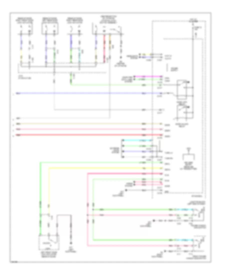
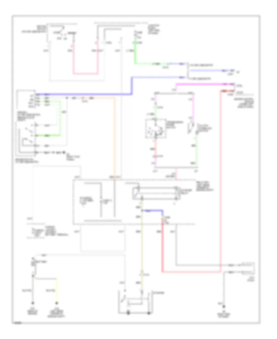
AIR CONDITIONING Automatic A/C Wiring Diagram (1 of 3) for Mitsubishi Mirage DE 2014 List of elements for Automatic A/C Wiring Diagram (1 of 3) for Mitsubishi Mirage DE 2014: 43 A/mp Air mixing damper control motor & potentiometer (bottom of heater assembly) Auto a/c controller assembly (center of dash) B/up Base Blower motor Blower relay C-402 C-403 C-404 C-405 Canh Canl Computer data lines system Cool Def Df sw Etacs-ecu Face Fre Fuse 15a Fuse 30a Fuse 7.5a G17 (left kick panel) Hot Hot at all times Hot in on or start Ig2 Ill+ Ill- Interior lights system J/c 9 (c-109) Junction block (left end of dash) Mode selection damper control motor & potentiometer (bottom of heater assembly) Modp Outside/inside air selection damper control motor Power distribution system Power transistor (on blower assembly) Rec Red Rvm Seng Snsb Automatic A/C Wiring Diagram (2 of 3) for Mitsubishi Mirage DE 2014 List of elements for Automatic A/C Wiring Diagram (2 of 3) for Mitsubishi Mirage DE 2014: 45 A-104 A/c compressor & clutch assembly A/c compressor relay A/c pressure sensor (right front of engine compt) Ac/p Ac/r Ac/t Acp5 & bvs5 Acpe & bvse Acte & fpre Ambient temperature sensor (behind left side of front fascia) Anti-lock brakes system C-212 C-225 C-227 C-228 Can h Can l Can transceiver circuit Cold temp ind Combination meter Computer data lines system Cooling fan control relay (high) Cooling fan control relay (low) Cpu Engine control module (ecu) (under left side of dash) Engine controls system Engine coolant temperature sensor (rear of engine) F/ hi F/ lo Fin thermo sensor (on heater assembly) Fuse 10a pnk Fusible link sbf1 40a red Hot at all times Hot temp ind Interface circuit J/c 3 (c-201) J/c 4 (c-219) J/c 7 (c-105) Led drive circuit Nca Red Relay box (left rear corner of engine compt) Seng Wts Automatic A/C Wiring Diagram (3 of 3) for Mitsubishi Mirage DE 2014 List of elements for Automatic A/C Wiring Diagram (3 of 3) for Mitsubishi Mirage DE 2014: 20 (center front of engine compt) cooling fan motor C-214 Computer data lines system Fusible link sbf5 40a Fusible link sbf6 40a Fusible link sbf7 40a G13 (in front of left front wheel) G14 (in front of left front wheel) G19 (left end of dash) G2 (right end of dash) Hot at all times J/c 2 (c-204) Nca Ptc heater Ptc heater control unit (right side of hvac blower) Ptc heater relay 1 Ptc heater relay 2 Ptc heater relay 3 Red Sub relay box (in front of battery)
ANTI-LOCK BRAKES Anti-lock Brakes Wiring Diagram for Mitsubishi Mirage DE 2014 List of elements for Anti-lock Brakes Wiring Diagram for Mitsubishi Mirage DE 2014: 73 (behind glove compt) oss-ecu (left end of dash) g19 + bm + bv Abs ind Asc off ind Asc off switch Asc on ind Asc-ecu Brake fluid level switch Brake ind C-211 C-212 C-213 C-404 C-405 C-416 Can h Can l Can transceiver circuit Combination meter Computer data lines system Cpu Etacs-ecu Exterior lights system Fl+ Fl- Fr + Fr- Fuse 15a Fuse 7.5a Fusible link 2 30a Fusible link 4 60a Fusible link box (on right battery terminal) G11 (right side of engine compt) G19 (left end of dash) G3 (right kick panel) G4 (under right rear of engine) Gnd 1 Gnd 2 Hot at all times Hot in on or start Hydraulic unit Ig1 Ill Interface circuit Interior lights system J/c 2 (c-204) J/c 7 (c-105) J/c 9 (c-109) Junction block (left end of dash) Led drive circuit Left front wheel speed sensor (on left front wheel hub assembly) Left rear wheel speed sensor (on left rear wheel hub assembly) Motor m Nca Parking brake switch Pnk Red Relay box (left rear corner of engine compt) Right front wheel speed sensor (on right front wheel hub assembly) Right rear wheel speed sensor (on right rear wheel hub assembly) Rl+ Rl- Rr+ Rr- Sensor pressure Solenoid valve Steering wheel sensor (in steering column) Stop light switch Stp 1 Swon System data lines computer
ANTI-THEFT Forced Entry Wiring Diagram, with Keyless Entry (1 of 4) for Mitsubishi Mirage DE 2014 List of elements for Forced Entry Wiring Diagram, with Keyless Entry (1 of 4) for Mitsubishi Mirage DE 2014: 47 (right kick panel) g3 Antg Antp Bkos C-103 C-104 C-124 C-22 Canh Canl Computer data lines system D-07 Driver's side lock/ unlock switch Driver's side outside transmission antenna assembly (left "b" pillar) Drrq Drvb Easg Easp Edrg Edrp Egtg Egtp Front inside transmission antenna assembly G17 (left kick panel) G4 (under right rear of engine) G9 (center of liftgate) Gnd Gndr Gtrq Ig1 Infg Infp Inrg Inrp Key slot Kos-ecu (right side of dash) Liftgate lock/unlock switch Liftgate outside transmission antenna assembly (behind center of liftgate) Nca Outer tone alarm (forward of left rear bumper) Passenger's side outside transmission antenna assembly (right "b" pillar) Pnk Pwr Pwrb Rear inside transmission antenna assembly (base of left "c" pillar) Red Uhf receiver Forced Entry Wiring Diagram, with Keyless Entry (2 of 4) for Mitsubishi Mirage DE 2014 List of elements for Forced Entry Wiring Diagram, with Keyless Entry (2 of 4) for Mitsubishi Mirage DE 2014: 38 +b1 +b2 Acc Bkos C-211 C-213 Cnbh Cnbl Computer data lines system Engine switch Exterior lights system Fuse 12 15a Fuse 13 7.5a G3 (right kick panel) Hot at all times Ig1 Ig2 Ig2m Illumination Ind (green) Ind (orange) Leda Ledg Ledw Nca Oss-ecu (behind glove compt) P range detection switch Pdsw Pgnd Power distribution system Red Relay box (left rear corner of engine compt) Selector lever assembly (cvt) (in center console) Sgnd Stop light switch Stp1 Sw1 Sw2 Forced Entry Wiring Diagram, with Keyless Entry (3 of 4) for Mitsubishi Mirage DE 2014 List of elements for Forced Entry Wiring Diagram, with Keyless Entry (3 of 4) for Mitsubishi Mirage DE 2014: 28 C-124 C-125 C-126 C-404 Can transceiver circuit Combination meter Computer data lines system Cpu Door ind Fuse 13 15a Fuse 15 7.5a G4 (under right rear of engine) Hot at all times Hot w/ ig1 relay energized J/c 6 (c-125 & c-126) J/c 7 (c-105) J/c 9 (c-109) Junction block (left end of dash) Kos ind Led drive circuit Left front door switch (left "b" pillar) Left rear door switch (base of left "c" pillar) Off Pnk Red Right front door switch (right "b" pillar) Right rear door switch (base of right "c" pillar) Tone alarm Forced Entry Wiring Diagram, with Keyless Entry (4 of 4) for Mitsubishi Mirage DE 2014 List of elements for Forced Entry Wiring Diagram, with Keyless Entry (4 of 4) for Mitsubishi Mirage DE 2014: 60 (center bottom of liftgate) liftgate latch switch assembly (rear of door) left rear door lock actuator (rear of door) right front door lock actuator (rear of door) right rear door lock actuator Adsw C-11 C-12 C-125 C-126 C-22 C-23 C-405 C-406 C-407 C-416 C-417 C-418 Canh Canl Computer data lines system D-02 D-07 D-14 D-ls D-us Ddsw Dhor Door Door lock relay Door unlock relay Dswl Dswu Etacs-ecu Exterior lights system F-04 F-14 F-15 Front power window sub switch Fuse 12 15a G17 (left kick panel) G3 (right kick panel) G9 (center of liftgate) Gnd H/lp hi H/lp lo Headlights system Horns system Hot at all times J/c 6 (c-125 & c-126) Junction block (left end of dash) Keyless entry receiver (w/ transmitter) Left front door lock actuator (rear of door) Lock Lock un Pnk Power window main switch Red Turn lh Turn rh Unlock Forced Entry Wiring Diagram, without Keyless Entry (1 of 2) for Mitsubishi Mirage DE 2014 List of elements for Forced Entry Wiring Diagram, without Keyless Entry (1 of 2) for Mitsubishi Mirage DE 2014: 65 (left Adsw C-11 C-12 C-22 C-23 C-404 C-405 C-406 C-407 C-416 C-417 C-418 Can transceiver circuit Canh Canl Combination meter Computer data lines system Cpu Ddsw Dhor Door Door ind Door lock relay Door unlock relay Driver's door unlock relay Dswl Dswu Etacs-ecu Exterior F-04 F-14 F-15 Front power window sub switch Fuse 12 15a Fuse 15 7.5a G17 G17 (left kick panel) G3 (right kick panel) G4 (under right rear of engine) H/lp hi H/lp lo Headlights system Hl 1+ Horns system Hot at all times Hot w/ ig1 relay energized J/c 7 (c-105) J/c 9 (c-109) Junction block (left end of dash) Key reminder switch Kick panel) Led drive circuit Left front door lock actuator (rear of door) Lights system Lock Nca Pnk Power window main switch Red Tone alarm Turn lh Turn rh Un lock Unlock Forced Entry Wiring Diagram, without Keyless Entry (2 of 2) for Mitsubishi Mirage DE 2014 List of elements for Forced Entry Wiring Diagram, without Keyless Entry (2 of 2) for Mitsubishi Mirage DE 2014: 20 (center bottom of liftgate) liftgate latch switch assembly (rear of door) left rear door lock actuator (rear of door) right front door lock actuator (rear of door) right rear door lock actuator C-11 C-124 C-125 C-126 D-02 D-07 D-14 G9 (center of liftgate) J/c 6 (c-125 & c-126) Left front door switch (left "b" pillar) Left rear door switch (base of left "c" pillar) Off Pnk Red Right front door switch (right "b" pillar) Right rear door switch (base of right "c" pillar) Immobilizer Wiring Diagram for Mitsubishi Mirage DE 2014 List of elements for Immobilizer Wiring Diagram for Mitsubishi Mirage DE 2014: 35 Ant+ Ant- C-228 C-403 C-404 C-407 C-416 C-417 Can transceiver circuit Canh Canl Combination meter Computer data lines system Cpu Dhor Engine control module (under left side of dash) Etacs-ecu Fuse 15a Fuse 7.5a G17 (left kick panel) G4 (under right rear of engine) Gnd Horns system Hot at all times Hot in on or start Ignition key Ignition key ring antenna Immobi ind J/c 7 (c-105) Junction block (left end of dash) Key reminder switch Led drive circuit Nca Pnk Red
BODY CONTROL MODULES Body Control Modules Wiring Diagram for Mitsubishi Mirage DE 2014 List of elements for Body Control Modules Wiring Diagram for Mitsubishi Mirage DE 2014: 83 A-113 Acc Adsw Ant+ Ant- Anti-theft system B pw Batt Bklp C-212 C-221 C-303 C-401 C-404 C-405 C-406 C-407 C-416 C-417 C-418 Can h Can l Computer data lines system Connector D-ls D-us Ddsw Def1 Defogger system Df sw Dhor Dlid Door Door locks & interior lights systems Door locks system Dswl Dswv Engine compt) Etacs-ecu Exterior lights system Fogy Fuse 10a Fuse 15a Fuse 20a Fuse 7.5a Fusible link sbf3 40a G11 (right side of G17 (left kick panel) Gnd H/lp hi H/lp lo Haz Headlights system Hl1+ Horns system Hot at all times Hot in acc Hot in on or acc Ig1 Ig2 Interior lights system Junction block (left end of dash) Lin Lock Off Pnk Power distribution system Power windows system Red Relay box (left rear corner of engine compt) Room Shift interlock system Slsc Spare a-108 Tail Turn lh Turn rh Un lock W/ kos Warning systems Washer Wiper Wiper/washer system
COMPUTER DATA LINES Computer Data Lines Wiring Diagram for Mitsubishi Mirage DE 2014 List of elements for Computer Data Lines Wiring Diagram for Mitsubishi Mirage DE 2014: 56 (under left side of dash) data link connector Asc-ecu Auto a/c controller assembly (a/c ecu) (center of dash) C-104 C-117 C-207 C-209 C-212 C-213 C-215 C-227 C-228 C-29 C-403 C-416 Can drive circuit Can h Can l Can transceiver circuit Can+ Can- Canh Canl Circuit Cnbh Cnbl Column switch Combination meter Cpu D-37 Data Diad Engine control module (ecm) (under left side of dash) Eps-ecu (under left center of dash) Etacs-ecu Fmb Fpcu Fuse 12 15a G4 (under right rear of engine) Hot at all times Interface circuit J/c (can1) (c-01) (left center of dash) J/c (can2) (c-203) J/c 10 (c-10) (left side of dash) Junction block (under left end of dash) Kos-ecu (w/ keyless operating system) (right side of dash) Lin Lin interface Occupant classification ecu (under passenger's seat) Oss-ecu (w/ keyless operating system) (behind glove compartment) Pnk Ptc heater control unit (right side of hvac blower) Red Srs-ecu (under front of center console) Steering wheel sensor (in steering column) Transaxle control module (under left side of dash)
COOLING FAN Cooling Fan Wiring Diagram for Mitsubishi Mirage DE 2014 List of elements for Cooling Fan Wiring Diagram for Mitsubishi Mirage DE 2014: 35 Auto a/c controller assembly (center of dash) C-225 C-228 C-404 C-405 Can transceiver circuit Canh Canl Cold temp ind Combination meter Computer data lines system Cooling fan control relay (high) Cooling fan control relay (low) Cooling fan motor (center front of engine compt) Cpu Engine control module (ecu) (under left side of dash) Engine coolant temperature sensor (rear of engine) F/hi F/lo Fuse 7.5a Fusible link sbf1 40a red G13 (in front of left front wheel) G14 (in front of left front wheel) Hot at all times Hot in on or start Hot temp ind J/c 3 (c-201) J/c 7 (c-105) J/c c-219 Junction block (left end of dash) Led drive circuit Red Relay box (left rear corner of engine compt) Seng Wts
CRUISE CONTROL Cruise Control Wiring Diagram (1 of 2) for Mitsubishi Mirage DE 2014 List of elements for Cruise Control Wiring Diagram (1 of 2) for Mitsubishi Mirage DE 2014: 53 (main) (sub) 120a Accelerator pedal position sensor (top of accelerator pedal assembly) Ap5 Ape Aps5 Apse Apsm Apss Back Bat1 Brk C-213 C-225 C-227 C-228 C/r C/rl Canh Canl Clms Clt1 Clutch interlock switch (m/t) Computer data lines system Engine control module (under left side of dash) Etv+ Etv- Fuse 15a Fuse 20a Fuse 7.5a Fusible link 6 Fusible link box G19 (left end of dash) G21 (under left side of dash) Gndb Hall ic Hot at all times Mfi relay Oss ecu (behind glove compt) Pnk Red Relay box (left rear corner of engine compt) Rsb Sw- Throttle actuator control motor Throttle actuator control motor relay Throttle body assembly (on input to intake manifold) Throttle position sensor Tps5 Tpse Tpsm Tpss Cruise Control Wiring Diagram (2 of 2) for Mitsubishi Mirage DE 2014 List of elements for Cruise Control Wiring Diagram (2 of 2) for Mitsubishi Mirage DE 2014: 48 C-209 C-210 C-219 C-220 C-301 C-306 C-403 C-404 C213 C215 Can transceiver circuit Cancel Canh Canl Clock spring Combination meter Computer data lines system Cpu Cruise Cruise control switch Cruise ind Exterior lights system Fuse 7.5a G2 (right end of dash) G4 (under right rear of engine) Hot in on or start Igsw Inhn Inhp Interface circuit Interior lights system J/c 2 (c-204) J/c 4 (c-219 & c220) J/c 7 (c-105) Junction block (left end of dash) Led drive circuit Nca Pnk Power distribution system Red Res+ Secondary speed sensor (top of transmission) Secs Set- Sgn2 Stop light switch Transaxle control module (cvt) (under left side of dash) Transmission range switch
DEFOGGERS Defoggers Wiring Diagram for Mitsubishi Mirage DE 2014 List of elements for Defoggers Wiring Diagram for Mitsubishi Mirage DE 2014: 27 (left kick panel) g17 Auto a/c controller assembly (center of dash) C-12 C-22 C-403 C-416 C-419 Computer data lines system D-07 Etacs-ecu Fuse 30a Fuse 7.5a G-02 G-11 G17 (left kick panel) G3 (right kick panel) G9 (center of liftgate) Hot at all times Hot in on or start Junction block (left end of dash) Left door mirror assembly Mirror heater Nca Rear window defogger Rear window defogger relay Red Right door mirror assembly
ELECTRONIC POWER STEERING Electronic Power Steering Wiring Diagram for Mitsubishi Mirage DE 2014 List of elements for Electronic Power Steering Wiring Diagram for Mitsubishi Mirage DE 2014: 34 +bb C-207 C-207-1 C-208 C-208-1 C-404 C-405 Can h Can l Can transceiver circuit Combination meter Computer data lines system Cpu Eps ind Eps-ecu (under left center of dash) Fuse 7.5a Fusible link 60a Fusible link box G18 (left kick panel) G4 (under right rear of engine) Gnd Hot at all times Hot in on or start Ig1 J/c 2 (c-204) J/c 7 (c-105) Junction block (left end of dash) Led drive circuit Red Torque sensor Tse Tsm Tss Tsv
ENGINE PERFORMANCE
1.2L 1.2L, Engine Performance Wiring Diagram (1 of 4) for Mitsubishi Mirage DE 2014 List of elements for 1.2L, Engine Performance Wiring Diagram (1 of 4) for Mitsubishi Mirage DE 2014: 59 (in exhaust, downstream of catalytic) rear heated oxygen sensor (main) (on input to intake manifold) throttle body assembly (sub) 0cv Afs Afs5 Afse Altf Altg Altl Ats C-225 C-226 Cil 1 Cil 2 Cil 3 Dgnd Engine control module (under left side of dash) Etv+ Etv- G5 (under left side of dash) Hall ic Inj 1 Inj 2 Inj 3 Injector Intake air temperature sensor K/s K/se Knock sensor (front of left side of engine) Lefl Lhfl Linear air-fuel ratio sensor (top of engine) Lpfl Lrl Lsfl Map Mass airflow sensor Mass airflow sensor (in output of air filter) Nca O2rl Ohrl Opsw Orle Pnk Purg Red Seng Sgc Sgt Starting/ charging system Throttle actuator control motor Throttle position sensor Tps5 Tpse Tpsm Tpss Wts 1.2L, Engine Performance Wiring Diagram (2 of 4) for Mitsubishi Mirage DE 2014 List of elements for 1.2L, Engine Performance Wiring Diagram (2 of 4) for Mitsubishi Mirage DE 2014: 23 (front of right side of engine) manifold absolute pressure sensor (on rear of engine) oil feeder control valve (right front of engine) crankshaft position sensor (right rear of engine) evaporative emission purge solenoid (top front of right side of engine) camshaft position sensor A-104 C-118 C-211 C-219 C-220 Engine oil pressure switch (lower left side of engine) Evaporative emission ventilation solenoid (under left rear of vehicle, on canister) G1 (right front of engine) Ignition coil 1 (top of engine) Ignition coil 2 (top of engine) Ignition coil 3 (top of engine) J/c 4 (c-219 & c-220) J/c 5 (c-202) Nca Plug spark Pnk Red Spark plug 1.2L, Engine Performance Wiring Diagram (3 of 4) for Mitsubishi Mirage DE 2014 List of elements for 1.2L, Engine Performance Wiring Diagram (3 of 4) for Mitsubishi Mirage DE 2014: 36 (on brake booster assembly) brake vacuum sensor (rear of engine) engine coolant temperature sensor (right front C-117 C-212 C-215 C-219 C-220 C-403 C-404 C-406 C-416 C-418 Can transceiver circuit Combination meter Computer data lines system Cpu Eco ind Etacs-ecu Fuel level sensor Fuel pump module (in fuel tank) Fuel pump relay Fuel tank temperature sensor Fuse 10a Fuse 7.5a G7 (front of right "c" pillar) Hot in on or start Interface circuit J/c 4 (c-219 & c-220) J/c 7 (c-105) Junction block (left end of dash) Led drive circuit Malfunction ind light Of engine compt) a/c pressure sensor Pnk Red 1.2L, Engine Performance Wiring Diagram (4 of 4) for Mitsubishi Mirage DE 2014 List of elements for 1.2L, Engine Performance Wiring Diagram (4 of 4) for Mitsubishi Mirage DE 2014: 76 (main) (sub) (top of accelerator pedal assembly) accelerator pedal position sensor Ac/p Ac/r Ac/t Acp5 & bvs5 Acpe & bvse Air conditioning system Ap5 Ape Aps5 Apse Apsm Apss Back Bat1 Brk Bvs C-117 C-212 C-213 C-227 C-228 C/r C/rl Canh Canl Clt 1 Cnbh Cnbl Computer data lines system Cooling fans system Cruise control system Diag Engine control module (under left side of dash) Exterior lights system F/hi F/lo F/pr F/tm Fmb Fp/r Fpr5 Fpre & acte Fuel tank differential pressure sensor (top of fuel tank) Fuse 15a Fuse 20a Fuse 7.5a Fusible link 6 120a Fusible link box (on right battery terminal) G19 (left end of dash) G2 (right end of dash) G21 (under left side of dash) Gndb Gnde Hall ic Hot at all times Ign J/c 2 (c-204) Mfi relay Oss-ecu (w/ keyless entry) (behind glove compt) P/vt Pnk Power distribution system Red Relay box (left rear corner of engine compt) Rsb Rsg Starting/ charging system Stcd Stoplight switch Stp 1 Strl Sw- Throttle actuator control motor relay
EXTERIOR LIGHTS Backup Lamps Wiring Diagram for Mitsubishi Mirage DE 2014 List of elements for Backup Lamps Wiring Diagram for Mitsubishi Mirage DE 2014: 33 Backup light switch C-06 C-07 C-117 C-211 C-213 C-215 C-219 C-220 C-403 Cvt Fuse 7.5a G10 (front of left "c" pillar) G7 (front of right "c" pillar) Hot in on or start J/c 12 (d-17) (under left rear door sill) J/c 13 (d-11) (near base of left "c" pillar) J/c 4 (c-219 & c-220) Junction block (left end of dash) Left backup light Left rear combination light M/t Multivision display Nca Pnk Power distribution system Radio & cd player Rev Right backup light Right rear combination light Transmission range switch W/ mmcs W/o mmcs Exterior Lamps Wiring Diagram (1 of 2) for Mitsubishi Mirage DE 2014 List of elements for Exterior Lamps Wiring Diagram (1 of 2) for Mitsubishi Mirage DE 2014: 55 Backup Backup lamps circuit Bklp C-211 C-212 C-405 C-406 C-407 C-416 C-418 D-07 Engine controls system Etacs-ecu Field effect transistor Fuse 1 7.5a Fuse 10a Fuse 15a Fuse 7 7.5a Fusible link sbf3 40a G10 (front of right "c" pillar) G12 (right side of engine compt) G14 (in front of left front wheel) G7 (front of right "c" pillar) G9 (center of liftgate) Haz High-mounted stoplight Hot at all times Integrated in liftgate Integrated in rear spoiler J/c 11 (d-19) J/c 13 (d-11) (near base of left "c" pillar) Junction block (left end of dash) Left front side marker light Left front turn signal light Left license plate light Left position light Left rear combination light Left side turn signal light Left turn signal light Nca Pnk Red Relay box (left rear corner of engine compt) Right front side marker light Right front turn signal light Right license plate light Right position light Right rear combination light Right side turn signal light Right turn signal light Stop Stop light switch Tail Tail light relay Turn Exterior Lamps Wiring Diagram (2 of 2) for Mitsubishi Mirage DE 2014 List of elements for Exterior Lamps Wiring Diagram (2 of 2) for Mitsubishi Mirage DE 2014: 43 (left "b" pillar) left front door switch C-213 C-214 C-404 C-416 Can h Can l Can transceiver circuit Column ecu Column switch Combination meter Computer data lines system Cpu Ddsw Etacs-ecu Fuse 13 15a Fuse 15 7.5a Fuse 7.5a G17 (left kick panel) G3 (right kick panel) G4 (under right rear of engine) Gnd Hazard warning switch Head Hot at all times Hot in on or start Interior lights system J/c 10 (c-10) (left side of dash) J/c 7 (c-105) J/c 9 (c-109) Junction block (left end of dash) Led drive circuit Left Left turn ind Lighting switch Lin interface Pnk Red Relay box (left rear corner of engine compt) Right Right turn ind Tail Turn signal light switch
GROUND DISTRIBUTION Ground Distribution Wiring Diagram for Mitsubishi Mirage DE 2014 List of elements for Ground Distribution Wiring Diagram for Mitsubishi Mirage DE 2014: 47 Accessory socket, radio & cd player, blower relay, power transistor, auto a/c controller assembly, junction block, etacs-ecu left front door lock actuator, driver side lock/unlock switch, power window main switch, hands free module, heated seat switch, heated seat relay, combination meter, multivision display, steering wheel multi-function switch, left door mirror assembly, heater control panel & hazard warning light switch Asc ecu, engine control module & ptc heater Asc off switch, steering wheel sensor, kos-ecu (w/ keyless entry), front power window sub switch, key reminder switch (when removing key on), column switch, blower switch, selector lever assembly, oss ecu, engine switch, ig1 relay, acc relay, ig2 relay, right door mirror assembly, remote controlled mirror switch & steering lock solenoid Battery Brake fluid level switch & spare connector (w/ keyless entry) Clutch interlock switch (m/t) engine control module Cooling fan motor Cooling fan motor, right fog light, right headlight, right front side marker light, right position light, right front turn signal light & right side turn signal light Cruise control switch & steering wheel multi-function switch D-07 Data link connector, combination meter, kos-ecu (w/ keyless entry) & srs ecu Driver side front seat belt switch Electric power steering ecu Front dome light Fuel pump module, left & right license plate light & left rear combination light G1 (right front of engine) G10 (front of left "c" pillar) G11 (right side of engine compt) G12 (right side of engine compt) G13 (in front of left front wheel) G14 (in front of left front wheel) G15 (rear of engine) G16 (left rear corner of engine compt) G17 (left kick panel) G18 (left kick panel) G19 (left end of dash) G2 (right end of dash) G20 (under driver seat) G21 (under left side of dash) G3 (right kick panel) G4 (under right rear of engine) G5 (under left side of dash) G6 (under front passenger seat) G7 (front of right "c" pillar) G8 (above front left corner of headliner) G9 (center of liftgate) Ignition coil 1, ignition coil 2 & ignition coil 3 J/c 13 (d-11) (near base of left "c" pillar) J/c 2 (c-204) J/c 9 (c-109) Left fog light left front side marker light, left position light, left headlight, left front turn signal light & left side turn signal light Left heated seat, right heated seat & occupant classification ecu Liftgate latch switch assembly, liftgate lock/unlock switch, rear window defogger, rear wiper motor & high mounted stoplight Nca Relay box, stoplight switch, starter relay, power window relay, ptc heater control unit, ptc heater relay 1, ptc heater relay 2, ptc heater relay 3 & windshield wiper motor Right rear combination light & left rear combination light Transaxle control module & linear air fuel ratio sensor shield
HEADLIGHTS Headlights Wiring Diagram (1 of 2) for Mitsubishi Mirage DE 2014 List of elements for Headlights Wiring Diagram (1 of 2) for Mitsubishi Mirage DE 2014: 46 A-105 Beam ind C-124 C-212 C-213 C-404 C-406 C-407 C-416 Can transceiver circuit Canh Canl Combination meter Computer data lines system Cpu Dosw Etacs-ecu Field effect transistor Fog ind Fog light relay Fogy Fuse 10a Fuse 15a Fuse 6 15a Fuse 7.5a G17 (left kick panel) Gnd H/lp hi h/lp lo Headlight relay (high) Headlight relay (low) Hot at all times Hot in on or start Interface circuit J/c 1 (a-106) J/c 7 (c-105) Junction block (left end of dash) Led drive circuit Left front door switch (left "b" pillar) Lin interface Off Parking brake switch Pnk Red Relay box (left rear corner of engine compt) W/ drl W/o drl Headlights Wiring Diagram (2 of 2) for Mitsubishi Mirage DE 2014 List of elements for Headlights Wiring Diagram (2 of 2) for Mitsubishi Mirage DE 2014: 23 Column switch Column-ecu Dimmer switch Fog lighting switch Fusible link 5 80a Fusible link box (on right battery terminal) G12 (right side of engine compt) G14 (in front of left front wheel) G3 (right kick panel) Head lighting switch Hot at all times J/c 10 (c-10) (left side of dash) J/c 9 (c-109) Left fog light Left headlight Lighting switch Off Pass Passing switch Red Right fog light Right headlight Tail lighting switch
HORN Horn Wiring Diagram for Mitsubishi Mirage DE 2014 List of elements for Horn Wiring Diagram for Mitsubishi Mirage DE 2014: 14 C-301 C-306 C-417 Clock spring Etacs-ecu Fuse 5 10a Horn (left front of engine compt) Horn relay Horn switch Hot at all times Junction block (left end of dash) Nca Pnk Relay box (left rear corner of engine compt)
INSTRUMENT CLUSTER Instrument Cluster Wiring Diagram (1 of 2) for Mitsubishi Mirage DE 2014 List of elements for Instrument Cluster Wiring Diagram (1 of 2) for Mitsubishi Mirage DE 2014: 58 Abs ind Ambient temperature sensor (behind left side of front fascia) Asc off ind Asc on ind Beam ind Brake ind C-09 C-117 C-212 C213 Can transceiver circuit Chg ind Cold temp ind Combination meter Computer data lines system Cpu Cruise ind Door ind Driver's seat belt ind Eco ind Eps ind Fog ind Fuel level sensor Fuel pump module (in fuel tank) Fuel tank temperature sensor Fuse 7.5a G17 (left kick panel) G4 (under right rear of engine) G7 (front of right "c" pillar) Hot at all times Hot temp ind Illum Illumination control circuit Immobi ind Interface circuit Interior lights system Kos ind Lcd (cvt failure cvt position cvt temp) Lcd (f/ga, odo/trip, service reminder information) outside temperature) Lcd (fuel warning) Led drive circuit Left turn ind Malfunction ind light (service engine soon or check engine lamp) Multi-information display switch Oil pressure ind Parking brake switch Pnk Radio & cd player Red Relay box (left rear corner of engine compt) Right turn ind Spd Speedometer Srs ind Tachometer Tone alarm Tpms ind Warning systems Instrument Cluster Wiring Diagram (2 of 2) for Mitsubishi Mirage DE 2014 List of elements for Instrument Cluster Wiring Diagram (2 of 2) for Mitsubishi Mirage DE 2014: 37 Brake fluid level switch C-117 C-124 C-125 C-126 C-212 C-225 C-227 C-228 C-404 C-416 Canh Canl Computer data lines system D-07 Engine control module (under left side of dash) Engine oil pressure switch (lower left side of engine) Etacs- ecu F/tm Fuse 7.5a G11 (right side of engine compt) G17 (left kick panel) G9 (center of liftgate) Gnd Hot in on or start J/c 6 (c-125 & c-126) J/c 7 (c-105) Junction block (left end of dash) Left front door switch (left "b" pillar) Left rear door switch (base of left "c" pillar) Liftgate latch switch assembly (center bottom of liftgate) Off Opsw Pnk Red Right front door switch (right "b" pillar) Right rear door switch (base of right "c" pillar)
INTERIOR LIGHTS Courtesy Lamps Wiring Diagram (1 of 2) for Mitsubishi Mirage DE 2014 List of elements for Courtesy Lamps Wiring Diagram (1 of 2) for Mitsubishi Mirage DE 2014: 43 Adsw C-124 C-401 C-403 C-404 C-407 C-416 C-417 Can h Can l Computer data lines system D-07 Ddsw Door Dswl Dswu Etacs +b Etacs-ecu Fet Fuse 15a Fuse 7.5a G17 (left kick panel) G3 (right kick panel) G9 (center of liftgate) Gnd Hl1+ Hot at all times Hot in on or start Ig1 J/c 7 (c-105) J/c 9 (c-109) Junction block (left end of dash) Key reminder switch Left front door switch (left front "b" pillar) Liftgate latch switch assembly (center bottom of liftgate) Luggage compartment light Off Pnk Red Right front door switch (right front "b" pillar) Room Room lp Sgnd Courtesy Lamps Wiring Diagram (2 of 2) for Mitsubishi Mirage DE 2014 List of elements for Courtesy Lamps Wiring Diagram (2 of 2) for Mitsubishi Mirage DE 2014: 19 C-125 C-126 C-22 Canh Canl Combination meter Computer data lines system Door Front dome light G17 (left kick panel) G8 (above front left corner of headliner) J/c 6 (c-125 & c-126) Left front door lock actuator (rear of door) Left rear door switch (base of left rear "c" pillar) Lock Off Red Right rear door switch (base of right rear "c" pillar) Un lock Instrument Illumination Wiring Diagram for Mitsubishi Mirage DE 2014 List of elements for Instrument Illumination Wiring Diagram for Mitsubishi Mirage DE 2014: 68 +b2 Asc off switch Auto a/c controller assembly (center of dash) C-06 C-07 C-213 C-301 C-306 C-404 C-406 C-407 C-416 Can h Can l Can transceiver circuit Canh Canl Clock spring Column switch Column-ecu Combination meter Computer data lines system Cpu Cruise control switch Dimmer switch Engine switch Etacs-ecu Fuse 15a Fuse 7.5a Fusible link sbf3 40a G17 (left kick panel) G3 (right kick panel) Gnd Gnd 1 Hazard warning light switch Head Heated seat switch Heater control panel Hot at all times Hot in on or start Ig1 Ill Ill+ Ill- Illumination control circuit Interface circuit J/c 10 (c-10) (left side of dash) J/c 7 (c-105) J/c 9 (c-109) Junction block (left end of dash) Led drive circuit Ledw Lighting switch Lin interface Multi vision display (w /mmes) Multi- information display switch Nca Oss-ecu (behind glove compt) Passing switch Pnk Pwm Radio & cd player Red Relay box (left rear corner of engine compt) Sgnd Steering wheel multi-function switch Tail Taillight relay
NAVIGATION Hands Free Module Wiring Diagram for Mitsubishi Mirage DE 2014 List of elements for Hands Free Module Wiring Diagram for Mitsubishi Mirage DE 2014: 52 (not used) (usb cable) nca C-09 C-213 C-301 C-306 C-32 C-34 Can h Can l Can transceiver circuit Ch dn Ch up Clock spring Combination meter Computer data lines system Cpu Fuse 14 7.5a G17 (left kick panel) Gnd Hands free module (center of dash) Hot at all times Ieh Iel Ill Interface circuit Interior lights system Mic+ Mic- Microphone unit (center front of roof) Mode Navg Navl Navr Nca Off hook On hook P-on Pnk Radio & cd display Red Relay box (left rear corner of engine compt) Rem+ Rem- Sh-a Sh-m Spd Speech Steering wheel multi-function switch Usb connector Vol dn Vol up Navigation Wiring Diagram for Mitsubishi Mirage DE 2014 List of elements for Navigation Wiring Diagram for Mitsubishi Mirage DE 2014: 74 (antenna feeder cable) (usb cable) Acc C-06 C-07 C-08 C-117 C-12 C-22 C-301 C-404 C306 Cacc Can h Can l Cdet Cgnd Ch dn Ch up Circuit interface Circuit transceiver can Clock spring Cmp+ Cmp- Combination meter Computer data lines system Cpu D-02 D-14 Fl+ Fl- Fr+ Fr- Fuse 13 15a Fuse 25 10a Fuse 7 7.5a G17 (left kick panel) Gnd & swg Gps antenna Hot at all times Hot in on or acc Hot w/ taillight relay energized Ill Ill+ Ill- Interior lights system J/c 9 (c-109) Junction block (left end of dash) Left front door speaker Left rear door speaker Mode Multivision display Navigation system Nca Off hook On hook Pnk Pole antenna Red Rev Right front door speaker Right rear door speaker Rl+ Rl- Rr+ Rr- Spd Speech Steering wheel multi-function switch Sw1 Transmissions system Usb connector Vol dn Vol up Rear View Camera Wiring Diagram for Mitsubishi Mirage DE 2014 List of elements for Rear View Camera Wiring Diagram for Mitsubishi Mirage DE 2014: 21 (left kick panel) g17 Acc C-06 C-07 C-08 C-124 C-404 Cacc Cdet Cgnd Cmp+ Cmp- D-08 Fuse 25 10a Gnd Hot in on or acc Junction block (left end of dash) Multivision display Nca Rearview camera (center of liftgate) Red
POWER DISTRIBUTION Power Distribution Wiring Diagram (1 of 3) for Mitsubishi Mirage DE 2014 List of elements for Power Distribution Wiring Diagram (1 of 3) for Mitsubishi Mirage DE 2014: 48 (left rear corner of engine compt) relay box (not used) A-105 A/c compressor relay Anti-lock brakes system Battery C-213 Cooling fan control relay (high) Cooling fan control relay (low) Electronic power steering system Engine controls & exterior lights systems Engine controls, instrument cluster & navigation systems Engine switch (w/ keyless entry) Exterior lights systems Fog light relay Fuse 10a Fuse 15a Fuse 7.5a Fuse bf1 n/a Fuse bf2 n/a Fusible link 1 175a Fusible link 2 80a Fusible link 3 60a Fusible link 4 60a Fusible link 5 80a Fusible link 6 120a Fusible link 7 125a Fusible link box (on right battery terminal) Fusible link sbf1 40a Fusible link sbf2 30a Fusible link sbf3 40a G3 (right kick panel) Headlight relay (high) Headlight relay (low) Horn relay Mfi relay Oss-ecu (behind glove compt) Pnk Power window relay Power windows system Red Starter relay Starting/ charging system Starting/charging, engine controls, instrument cluster & navigation systems Throttle actuator control motor relay To junction block (diagram 2 of 3) To sub relay box (diagram 3 of 3) Transmissions system Power Distribution Wiring Diagram (2 of 3) for Mitsubishi Mirage DE 2014 List of elements for Power Distribution Wiring Diagram (2 of 3) for Mitsubishi Mirage DE 2014: 48 (left end of dash) junction block (not used) Acc Acc relay Air conditioning system Blower relay C-401 C-402 C-403 C-404 C-405 C-406 C-407 C-408 C-418 Door lock relay Door locks & anti-theft systems Door locks, computer data lines & anti-theft systems Door unlock relay Driver's door unlock relay (w/o keyless entry) Etacs-ecu Exterior lights system Exterior lights, wiper/washer & headlights systems From fusible a link box (diagram 1 of 3) From relay box c (diagram 1 of 3) Fuse 10a Fuse 15a Fuse 20a Fuse 30a Fuse 7.5a Fuse n/a G3 (right kick panel) Heated seat relay Ig1 Ig1 relay Ig2 Ig2 relay Interior lights system J/c 9 (c-109) Navigation & sound systems Oss-ecu (behind glove compt) Rear window defogger relay Red Taillight relay To ignition switch (diagram 3 of 3) To junction block (diagram 3 of 3) W/ keyless entry W/o keyless entry Power Distribution Wiring Diagram (3 of 3) for Mitsubishi Mirage DE 2014 List of elements for Power Distribution Wiring Diagram (3 of 3) for Mitsubishi Mirage DE 2014: 55 (+) (-) (left end of dash) junction block (or red) Acc Accessory socket Air conditioning & seats systems Air conditioning system Anti-lock brakes system Blower relay C-402 C-403 C-404 C-405 C-406 C-407 C-416 C-417 C-418 Door locks & anti-theft Door locks, wiper/washer & anti-theft Engine controls system Etacs-ecu From b fusible link box (diagram 1 of 3) From e acc relay (diagram 2 of 3) From f ig2 relay (diagram 2 of 3) From g junction block (diagram 2 of 3) From ig1 relay (diagram 2 of 3) Fuel pump relay Fuse 10a Fuse 15a Fuse 20a Fuse 7.5a Fusible link sbf5 40a Fusible link sbf6 40a Fusible link sbf7 40a G17 (left kick panel) Headlights & exterior lights systems Heated seat relay Ignition switch Instrument cluster system J/c 7 (c-105) Lock Mirrors system Navigation & sound systems Pnk Rear window defogger relay Red Shift interlock system Start Sub relay box (in front of battery) Systems W/ keyless entry W/o keyless entry Wiper/washer system
POWER DOOR LOCKS Power Door Locks Wiring Diagram, with Keyless Entry (1 of 4) for Mitsubishi Mirage DE 2014 List of elements for Power Door Locks Wiring Diagram, with Keyless Entry (1 of 4) for Mitsubishi Mirage DE 2014: 47 (right kick panel) g3 Antg Antp Bkos C-103 C-104 C-124 C-22 Canh Canl Computer data lines system D-07 Driver's side lock/ unlock switch Driver's side outside transmission antenna assembly (left "b" pillar) Drrq Drvb Easg Easp Edrg Edrp Egtg Egtp Front inside transmission antenna assembly G17 (left kick panel) G4 (under right rear of engine) G9 (center of liftgate) Gnd Gndr Gtrq Ig1 Infg Infp Inrg Inrp Key slot Kos-ecu (right side of dash) Liftgate lock/unlock switch Liftgate outside transmission antenna assembly (behind center of liftgate) Nca Outer tone alarm (forward of left rear bumper) Passenger's side outside transmission antenna assembly (right "b" pillar) Pnk Pwr Pwrb Rear inside transmission antenna assembly (base of left "c" pillar) Red Uhf receiver Power Door Locks Wiring Diagram, with Keyless Entry (2 of 4) for Mitsubishi Mirage DE 2014 List of elements for Power Door Locks Wiring Diagram, with Keyless Entry (2 of 4) for Mitsubishi Mirage DE 2014: 38 +b1 +b2 Acc Bkos C-211 C-213 Cnbh Cnbl Computer data lines system Engine switch Exterior lights system Fuse 12 15a Fuse 13 7.5a G3 (right kick panel) Hot at all times Ig1 Ig2 Ig2m Illumination Ind (green) Ind (orange) Leda Ledg Ledw Nca Oss-ecu (behind glove compt) P range detection switch Pdsw Pgnd Power distribution system Red Relay box (left rear corner of engine compt) Selector lever assembly (cvt) (in center console) Sgnd Stop light switch Stp1 Sw1 Sw2 Power Door Locks Wiring Diagram, with Keyless Entry (3 of 4) for Mitsubishi Mirage DE 2014 List of elements for Power Door Locks Wiring Diagram, with Keyless Entry (3 of 4) for Mitsubishi Mirage DE 2014: 28 C-124 C-125 C-126 C-404 Can transceiver circuit Combination meter Computer data lines system Cpu Door ind Fuse 13 15a Fuse 15 7.5a G4 (under right rear of engine) Hot at all times Hot w/ ig1 relay energized J/c 6 (c-125 & c-126) J/c 7 (c-105) J/c 9 (c-109) Junction block (left end of dash) Kos ind Led drive circuit Left front door switch (left "b" pillar) Left rear door switch (base of left "c" pillar) Off Pnk Red Right front door switch (right "b" pillar) Right rear door switch (base of right "c" pillar) Tone alarm Power Door Locks Wiring Diagram, with Keyless Entry (4 of 4) for Mitsubishi Mirage DE 2014 List of elements for Power Door Locks Wiring Diagram, with Keyless Entry (4 of 4) for Mitsubishi Mirage DE 2014: 60 (center bottom of liftgate) liftgate latch switch assembly (rear of door) left rear door lock actuator (rear of door) right front door lock actuator (rear of door) right rear door lock actuator Adsw C-11 C-12 C-125 C-126 C-22 C-23 C-405 C-406 C-407 C-416 C-417 C-418 Canh Canl Computer data lines system D-02 D-07 D-14 D-ls D-us Ddsw Dhor Door Door lock relay Door unlock relay Dswl Dswu Etacs-ecu Exterior lights system F-04 F-14 F-15 Front power window sub switch Fuse 12 15a G17 (left kick panel) G3 (right kick panel) G9 (center of liftgate) Gnd H/lp hi H/lp lo Headlights system Horns system Hot at all times J/c 6 (c-125 & c-126) Junction block (left end of dash) Keyless entry receiver (w/ transmitter) Left front door lock actuator (rear of door) Lock Lock un Pnk Power window main switch Red Turn lh Turn rh Unlock Power Door Locks Wiring Diagram, without Keyless Entry (1 of 2) for Mitsubishi Mirage DE 2014 List of elements for Power Door Locks Wiring Diagram, without Keyless Entry (1 of 2) for Mitsubishi Mirage DE 2014: 65 (left Adsw C-11 C-12 C-22 C-23 C-404 C-405 C-406 C-407 C-416 C-417 C-418 Can transceiver circuit Canh Canl Combination meter Computer data lines system Cpu Ddsw Dhor Door Door ind Door lock relay Door unlock relay Driver's door unlock relay Dswl Dswu Etacs-ecu Exterior F-04 F-14 F-15 Front power window sub switch Fuse 12 15a Fuse 15 7.5a G17 G17 (left kick panel) G3 (right kick panel) G4 (under right rear of engine) H/lp hi H/lp lo Headlights system Hl 1+ Horns system Hot at all times Hot w/ ig1 relay energized J/c 7 (c-105) J/c 9 (c-109) Junction block (left end of dash) Key reminder switch Kick panel) Led drive circuit Left front door lock actuator (rear of door) Lights system Lock Nca Pnk Power window main switch Red Tone alarm Turn lh Turn rh Un lock Unlock Power Door Locks Wiring Diagram, without Keyless Entry (2 of 2) for Mitsubishi Mirage DE 2014 List of elements for Power Door Locks Wiring Diagram, without Keyless Entry (2 of 2) for Mitsubishi Mirage DE 2014: 20 (center bottom of liftgate) liftgate latch switch assembly (rear of door) left rear door lock actuator (rear of door) right front door lock actuator (rear of door) right rear door lock actuator C-11 C-124 C-125 C-126 D-02 D-07 D-14 G9 (center of liftgate) J/c 6 (c-125 & c-126) Left front door switch (left "b" pillar) Left rear door switch (base of left "c" pillar) Off Pnk Red Right front door switch (right "b" pillar) Right rear door switch (base of right "c" pillar)
POWER MIRRORS Power Mirrors Wiring Diagram for Mitsubishi Mirage DE 2014 List of elements for Power Mirrors Wiring Diagram for Mitsubishi Mirage DE 2014: 30 (left kick panel) g17 C-12 C-22 C-403 Defogger system Down operation switch Fuse 8 7.5a G3 (right kick panel) Heater Horizontal Hot in on or start J/c 8 (c-107) J/c 9 (c-109) Junction block (left end of dash) Left Left door mirror assembly Left operation switch Motor Movement horizontal Movement motor Nca Off Pnk Red Remote controlled mirror switch Right Right door mirror assembly Right operation switch Up operation switch Vertical movement motor
POWER SEATS Power Seats Wiring Diagram for Mitsubishi Mirage DE 2014 List of elements for Power Seats Wiring Diagram for Mitsubishi Mirage DE 2014: 23 C-118 C-403 C-404 Fuse 16 7.5a Fuse 17 20a G17 (left kick panel) G6 (under front passenger seat) Heated seat relay Heated seat switch Hot at all times Hot in on or start Ill Interior lights system Junction block (under left end of dash) Left heated seat Nca Off Pnk Red Right heated seat Seat back heater Seat cushion heater Thermostat
POWER WINDOWS Power Windows Wiring Diagram, with Safety Power Windows (1 of 2) for Mitsubishi Mirage DE 2014 List of elements for Power Windows Wiring Diagram, with Safety Power Windows (1 of 2) for Mitsubishi Mirage DE 2014: 40 (right end of dash) g2 Auto down Auto up C-118 C-211 C-214 C-23 Cpu D-02 D-14 Door lock switch Door locks system Down F-04 F-15 Fusible link sbf 4 40a G17 (left kick panel) Ill J/c 11 (d-19) J/c 2 (c-204) Left front power window motor Left front power window switch Left rear power window motor Left rear power window sub switch Left rear power window switch Lock Main switch Off Pnk Power window Power window lock switch Power window relay Red Relay box (left rear corner of engine compt) Right front power window switch Right rear power window motor Right rear power window sub switch Right rear power window switch Un lock Unlock Power Windows Wiring Diagram, with Safety Power Windows (2 of 2) for Mitsubishi Mirage DE 2014 List of elements for Power Windows Wiring Diagram, with Safety Power Windows (2 of 2) for Mitsubishi Mirage DE 2014: 25 Adsw B pw C-11 C-124 C-213 C-416 Can h Can l Computer data lines system Ddsw Down Etacs-ecu Front power window sub switch Fusible link 6 120a Fusible link box (on right battery terminal) G17 (left kick panel) Gnd Hot at all times Junction block (left end of dash) Left front door switch (left "b" pillar) Off Pnk Red Right front door switch (right "b" pillar) Right front power window motor Power Windows Wiring Diagram, without Safety Power Windows (1 of 2) for Mitsubishi Mirage DE 2014 List of elements for Power Windows Wiring Diagram, without Safety Power Windows (1 of 2) for Mitsubishi Mirage DE 2014: 31 (right end of dash) g2 Auto down C-11 C-214 C-23 Door lock switch Door locks system Down Down relay F-13 F-15 Front power window sub switch Fusible link sbf 4 40a G17 (left kick panel) J/c 2 (c-204) Left front power window lock switch Left front power window motor Lock Main switch Off Pnk Power window Power window lock switch Power window relay Red Relay box (left rear corner of engine compt) Right front power window motor Right front power window switch Un lock Unlock Up relay Power Windows Wiring Diagram, without Safety Power Windows (2 of 2) for Mitsubishi Mirage DE 2014 List of elements for Power Windows Wiring Diagram, without Safety Power Windows (2 of 2) for Mitsubishi Mirage DE 2014: 20 Adsw B pw C-124 C-213 C-416 Can h Can l Computer data lines system Ddsw Etacs-ecu Fusible link 6 120a Fusible link box (on right battery terminal) G17 (left kick panel) Gnd Hot at all times Junction block (left end of dash) Left front door switch (left "b" pillar) Pnk Red Right front door switch (right "b" pillar)
RADIO Radio Wiring Diagram, with Multi-Communication System for Mitsubishi Mirage DE 2014 List of elements for Radio Wiring Diagram, with Multi-Communication System for Mitsubishi Mirage DE 2014: 74 (antenna feeder cable) (usb cable) Acc C-06 C-07 C-08 C-117 C-12 C-22 C-301 C-404 C306 Cacc Can h Can l Cdet Cgnd Ch dn Ch up Circuit interface Circuit transceiver can Clock spring Cmp+ Cmp- Combination meter Computer data lines system Cpu D-02 D-14 Fl+ Fl- Fr+ Fr- Fuse 13 15a Fuse 25 10a Fuse 7 7.5a G17 (left kick panel) Gnd & swg Gps antenna Hot at all times Hot in on or acc Hot w/ taillight relay energized Ill Ill+ Ill- Interior lights system J/c 9 (c-109) Junction block (left end of dash) Left front door speaker Left rear door speaker Mode Multivision display Navigation system Nca Off hook On hook Pnk Pole antenna Red Rev Right front door speaker Right rear door speaker Rl+ Rl- Rr+ Rr- Spd Speech Steering wheel multi-function switch Sw1 Transmissions system Usb connector Vol dn Vol up Radio Wiring Diagram, without Multi-Communication System for Mitsubishi Mirage DE 2014 List of elements for Radio Wiring Diagram, without Multi-Communication System for Mitsubishi Mirage DE 2014: 73 (antenna feeder cable) (usb cable) (w/o hands free) usb connector Acc C-09 C-117 C-12 C-22 C-301 C-34 C-404 C306 Can h Can l Ch dn Ch up Circuit interface Circuit transceiver can Clock spring Combination meter Computer data lines system Cpu D-02 D-14 Fl+ Fl- Fr+ Fr- Fuse 13 15a Fuse 25 10a Fuse 7 7.5a G17 (left kick panel) Gnd Hot at all times Hot in on or acc Hot w/ taillight relay energized Ieh Iel Ill Ill+ Ill- Interior lights system J/c 9 (c-109) Junction block (left end of dash) Left front door speaker Left rear door speaker Mode Navg Navigation system Navl Navr Nca Off hook On hook P-on Pnk Pole antenna Radio & cd player Red Rem+ Rem- Right front door speaker Right rear door speaker Rl+ Rl- Rr+ Rr- Spd Speech Steering wheel multi-function switch Transmissions system Vol dn Vol up
SHIFT INTERLOCK Shift Interlock Wiring Diagram for Mitsubishi Mirage DE 2014 List of elements for Shift Interlock Wiring Diagram for Mitsubishi Mirage DE 2014: 28 Bklp C-212 C-404 C-416 Etacs-ecu Exterior lights system Fuse 10a Fuse 15a Fuse 7.5a G3 (right kick panel) Hot at all times Hot in on or acc Hot in on or start J/c 7 (c-105) J/c 9 (c-109) Junction block (left end of dash) Key lock relay (w/o keyless entry) Nca Oss-ecu (behind glove compt) P range detection switch Power distribution system Relay box (left rear corner of engine compt) Selector lever assembly (in center console) Shift lock solenoid Slso Steering lock solenoid (w/o keyless entry) (in steering wheel) Stop light switch Stp 1
STARTING/CHARGING Charging Wiring Diagram for Mitsubishi Mirage DE 2014 List of elements for Charging Wiring Diagram for Mitsubishi Mirage DE 2014: 31 7.5a A-104 Altf Altg Altl Battery C-225 C-228 C-404 Can transceiver circuit Canh Canl Charging ind Combination meter Computer data lines system Cpu Engine control module (under left side of dash) Fuse Fusible link 1 175a Fusible link 6 120a Fusible link box (on right battery terminal) G15 (rear of engine) G16 (left rear corner of engine compt) Generator Hot in on or start J/c 7 (c-105) Junction block (left end of dash) Led drive circuit Red Relay box (left rear corner of engine compt) Starting circuit Starting Wiring Diagram for Mitsubishi Mirage DE 2014 List of elements for Starting Wiring Diagram for Mitsubishi Mirage DE 2014: 43 +b2 A-104 Acc Battery C-212 C-213 C-215 C-227 C-228 C-402 C-406 Clutch interlock switch Cvt Engine control module (under left side of dash) Engine switch (w/ keyless entry) Fuse 13 7.5a Fuse 7.5a Fusible link 6 120a Fusible link box (on right battery terminal) Fusible link sbf3 40a G15 (rear of engine) G16 (left rear corner of engine compt) G2 (right end of dash) G3 (right kick panel) Ignition switch (w/o keyless entry) J/c 2 (c-204) Junction block (left end of dash) Lock M/t Oss ecu (w/ keyless entry) (behind glove compt) Pnk Red Relay box (left rear corner of engine compt) Start Starter Starter relay Stcd Strl Sw1 Sw2 Transmission range switch W/ keyless entry W/o keyless entry
SUPPLEMENTAL RESTRAINTS Supplemental Restraints Wiring Diagram (1 of 4) for Mitsubishi Mirage DE 2014 List of elements for Supplemental Restraints Wiring Diagram (1 of 4) for Mitsubishi Mirage DE 2014: 41 (base of right "b" pillar) right seat belt pretensioner (connector coupled: on) (connector uncoupled: off) connector lock switch Air bag off indicator light (passenger's side) C-27 C-28 C-32 C-403 C-404 Cls+ Cls- Connector lock switch (connector coupled: on) (connector uncoupled: off) Crs+ Crs- Driver's side front seat belt switch (in driver's seat belt buckle) Fuse 7.5a G20 (under driver seat) Hot in on or start Junction block (left end of dash) Nca Off Passenger's air bag off indicator light assembly Passenger's seat belt ind Passenger's side front seat belt switch (in passenger's seat belt buckle) Pbs- Pbso Pnk Pta+ Pta- Ptd+ Ptd- Red Right side impact sensor (near base of right "b" pillar) Sls+ Sls- Srs ecu (under front of center console) Srs+ Srs- Ssl+ Ssl- Ssr+ Ssr- Supplemental Restraints Wiring Diagram (2 of 4) for Mitsubishi Mirage DE 2014 List of elements for Supplemental Restraints Wiring Diagram (2 of 4) for Mitsubishi Mirage DE 2014: 11 (base of left "b" pillar) left seat belt pretensioner (outer edge of left front seat back) left side air bag module squib (outer edge of right front seat back) right side air bag module squib Connector lock switch (connector coupled: on) (connector uncoupled: off) Left curtain air bag module squib (top of left "c" pillar) Left side impact sensor (near base of left "b" pillar) Nca Off Pnk Red Right curtain air bag module squib (top of right "c" pillar) Supplemental Restraints Wiring Diagram (3 of 4) for Mitsubishi Mirage DE 2014 List of elements for Supplemental Restraints Wiring Diagram (3 of 4) for Mitsubishi Mirage DE 2014: 34 4wd C-117 C-124 C-213 C-32 Can transceiver circuit Canh Canl Capacitor sensor Combination meter Computer data lines system Cpu D-37 D-37-1 Driver's seat belt ind Fuse 7.5a G4 (under right rear of engine) G6 (under front passenger seat) Gnd Guard Guard a Hot at all times Interface circuit J/c 7 (c-105) Led drive circuit Occupant classification ecu (under passenger's seat) Pnk Power distribution system Red Relay box (left rear corner of engine compt) Sense Sense c Shield (guard) Srs ind Supplemental Restraints Wiring Diagram (4 of 4) for Mitsubishi Mirage DE 2014 List of elements for Supplemental Restraints Wiring Diagram (4 of 4) for Mitsubishi Mirage DE 2014: 41 (connector coupled: on) (connector uncoupled: off) connector lock switch (connector coupled: on) connector uncoupled: off) connector lock switch Aq2+ Aq2- Asq+ Asq- C-02 C-212 C-29 C-309 C-314 C-35 Can+ Can- Clock spring Computer data lines system Connector lock switch (connector coupled: on) (connector uncoupled: off) Dq1+ Dq1- Dq2+ Dq2- Driver's air bag module squib Driver's knee air bag module squib Flh+ Flh- Frh+ Frh- Front passenger's air bag module squib G4 (under right rear of engine) Gnd1 Ig1a Ig1b Kds+ Kds- Left front impact sensor (left front corner of engine compt) Off Oflp Pnk Red Right front impact sensor (right front corner of engine compt) Srs ecu (under front of center console)
TRANSMISSION Transmission Wiring Diagram (1 of 2) for Mitsubishi Mirage DE 2014 List of elements for Transmission Wiring Diagram (1 of 2) for Mitsubishi Mirage DE 2014: 54 (on rear of transmission) output speed sensor (on top of transmission) primary speed sensor (top of transmission) secondary speed sensor Bat2 Batt C-209 C-210 Canh Canl Computer data lines system Cvt assembly Cvt fluid temperature sensor Diad Fpcu Fuse 15a G5 (under left side of dash) Gnd1 Gnd2 High clutch & reverse brake solenoid Hot at all times Hrls Igsw Inhd Inhl Inhn Inhp Inhr Lbls Line pressure solenoid Lock-up solenoid Low brake solenoid Lprs Luls Outs Plls Pnk Primary pressure solenoid Prls Prms Red Relay box (left rear corner of engine compt) Rom-assembly Rom1 Rom2 Rom3 Secondary pressure sensor Secs Sgn2 Sgnd Spwr Sspw Starting/ charging system Transaxle control module (under left side of dash) Transmission range switch Transmission Wiring Diagram (2 of 2) for Mitsubishi Mirage DE 2014 List of elements for Transmission Wiring Diagram (2 of 2) for Mitsubishi Mirage DE 2014: 29 Bklp C-212 C-213 C-215 C-219 C-220 C-403 C-416 Can drive circuit Can transceiver circuit Canh Canl Combination meter Computer data lines system Cpu Etacs-ecu (behind junction block) Exterior lights system Fuse 15a Fuse 7.5a Hot at all times Hot in on or start Interface circuit J/c 4 (c-219 & c-220) Junction block (under left end of dash) Lcd (cvt position cvt temperature cvt failure) Pnk Red Relay box (left rear corner of engine compt) Stoplight switch
WARNING SYSTEMS Chime Wiring Diagram for Mitsubishi Mirage DE 2014 List of elements for Chime Wiring Diagram for Mitsubishi Mirage DE 2014: 57 Brake fluid level switch Brake ind C-123 C-124 C-212 C-28 C-29 C-32 C-403 C-404 C-416 Can Can drive circuit Can+ Can- Circuit drive led Circuit transceiver Column ecu Column switch (on steering column) Combination meter Computer data lines system Cpu Ddsw Driver's seat belt ind Driver's side seat belt switch (in driver's seat belt buckle) Etacs-ecu Fuse 15a Fuse 7.5a G11 (right side of engine compt) G20 (under driver seat) G3 (right kick panel) G4 (under right rear of engine) Head Hl1+ Hot at all times Hot in on or start Interface circuit J/c 10 (c-10) (left side of dash) J/c 7 (c-105) J/c 9 (c-109) Junction block (left end of dash) Key reminder switch Left front door switch (left front "b" pillar) Lighting switch Lin interface Nca Parking brake switch Passenger's air bag off indicator light assembly Passenger's seat belt switch (in passenger's seat belt buckle) Pbs- Pbso Pnk Red Relay box (left rear corner of engine compt) Srs-ecu (under front of center console) Tail Tone alarm Tire Pressure Monitoring Wiring Diagram for Mitsubishi Mirage DE 2014 List of elements for Tire Pressure Monitoring Wiring Diagram for Mitsubishi Mirage DE 2014: 44 (c-109) (inside tire/wheel assemblies) (w/ kos) (right side of dash) Bkos C-103 C-104 C-123 C-404 Cab h Cab l Can transceiver Canh Canl Circuit Combination meter Computer data lines system Cpu Etacs-ecu Fuse 15a Fuse 7.5a G3 (right kick panel) G4 (under right rear of engine) Gnd Hot at all times Hot in on or start Ig1 J/c 7 (c-105) J/c 9 Junction block (left end of dash) Keyless entry receiver (w/o kos) Kos-ecu Led drive circuit Left front tire pressure sensor Left rear tire pressure sensor Oss-ecu (w/ kos) (behind glove compt) Pnk Pwr Red Relay box (left rear corner of engine compt) Right front tire pressure sensor Right rear tire pressure sensor Solid state Tpms ind Uhf receiver
WIPER/WASHER Front Wiper/Washer Wiring Diagram for Mitsubishi Mirage DE 2014 List of elements for Front Wiper/Washer Wiring Diagram for Mitsubishi Mirage DE 2014: 49 (hi) (int) (lo) (mist) All times C-308-1 C-403 C-404 C-405 C-407 C-416 C-417 Circuit breaker Column ecu Column switch Computer data lines system Etacs-ecu Fast Fuse 10 7.5a Fuse 13 15a Fuse 15 7.5a Fuse 20 20a Fuse 26 15a G17 (left kick panel) G2 (right end of dash) G3 (right kick panel) Gnd Hot at Hot in on or acc Hot in on or start J/c 10 (c-10) (left side of dash) J/c 2 (c-204) J/c 7 (c-105) J/c 9 (c-109) Junction block (left end of dash) Lin interface Off Power distribution system Rear washer relay Red Slow Windshield intermittent wiper interval adjusting switch Windshield washer motor (in washer reservoir) Windshield washer relay Windshield washer switch Windshield wiper automatic stop relay Windshield wiper motor (center rear engine compt) Windshield wiper speed switching relay Windshield wiper switch Rear Wiper/Washer Wiring Diagram for Mitsubishi Mirage DE 2014 List of elements for Rear Wiper/Washer Wiring Diagram for Mitsubishi Mirage DE 2014: 53 (right kick panel) g3 All times C-209 C-213 C-215 C-219 C-220 C-308-1 C-403 C-404 C-405 C-407 C-416 C-418 Can h Can l Circuit breaker Column ecu Column switch Computer data lines system D-07 Etacs ecu Fuse 13 15a Fuse 14 15a Fuse 15 7.5a Fuse 26 15a G17 (left kick panel) G9 (center of liftgate) Gnd Hot at Hot in on Hot in on or acc Inhr J/c 10 (c-10) (left side of dash) J/c 4 (c-219 & (c-220) J/c 4 (c-220) J/c 7 (c-105) J/c 9 (c-109) Junction block (left end of dash) Lin interface Off Or start Pnk Power distribution system Rear washer relay Rear washer switch Rear wiper motor (center of liftgate) Rear wiper relay Rear wiper switch Transaxle control module Transmission range switch Windshield washer motor (in washer reservoir) Windshield washer relay