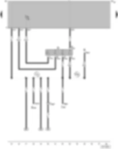
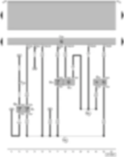
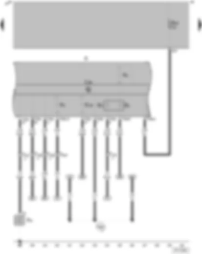
| A | Battery |
| B | Starter |
| C | Alternator |
| C1 | Voltage regulator |
| T1ag | Single connector, on starter |
| T2bo | 2-pin connector, on alternator |
| T2v | 2-pin connector, near battery |
| 1 | Earth strap, battery body |
| 49 | Earth point, near battery |
| 500 | Screw connection -1- (30), on relay plate |
| 501 | Screw connection -2- (30), on relay plate |
| D26 | Positive connection (B+), in alternator wiring harness |
| P1 | Positive connection (30), in fuse holder/battery |
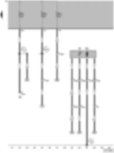
| D | Ignition/starter switch |
| E165 | Rear lid release switch |
| J59 | X contact relief relay |
| J362 | Immobilizer control unit |
| R | Radio |
| T6m | 6-pin connector, in tailgate/boot lid release switch |
| T7c | 7-pin connector, on ignition/starter switch |
| T8g | 8-pin connector, on immobilizer control unit |
| T8h | 8-pin connector, on radio |
| T10g | 10-pin connector, (black) behind shelf - front passenger's side |
| A2 | Positive connection (15), in dash panel wiring harness |
| A78 | Connection (SU), in dash panel wiring harness |
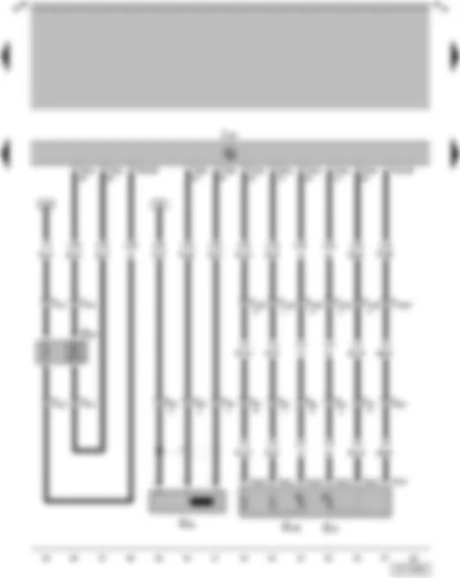
| F | Brake light switch |
| F36 | Clutch pedal switch |
| F47 | Cruise control system brake pedal switch (diesel direct injection system) |
| G61 | Knock sensor I |
| J537 | 4LV (injection system) control unit |
| M9 | Brake light bulb, left |
| M10 | Brake light bulb, right |
| T2au | 2-pin connector, on knock sensor I |
| T4t | 4-pin connector, behind freight compartment, left |
| T4u | 4-pin connector, on clutch pedal switch |
| T5l | 5-pin connector, on tail light, left |
| T5m | 5-pin connector, on tail light, right |
| T6k | 6-pin connector, (lilac) next to relay plate |
| T10e | 10-pin connector, (red) behind shelf - front passenger's side |
| T40a | 40-pin connector, on 4LV (injection system) control unit |
| T81a | 81-pin connector, on 4LV (injection system) control unit |
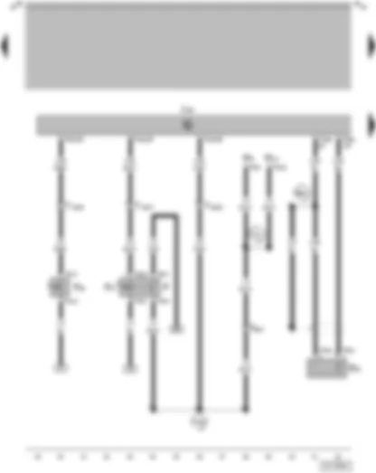
| A18 | Connection (54), in dash panel wiring harness |
| E52 | Connection (screening), in injection system wiring harness |
| W1 | Positive connection -1- (54) in rear wiring harness |
| G22 | Speedometer sender (Hall sender on gearbox) |
| J209 | Fresh air blower and radiator fan relay |
| J537 | 4LV (injection system) control unit |
| T3g | 3-pin connector, on speedometer sender |
| T6g | 6-pin connector, (grey) next to relay plate |
| T9b | 9-pin connector, on fresh air blower and radiator fan relay |
| T10f | 10-pin connector, (brown) behind shelf - front passenger's side |
| T81a | 81-pin connector, on 4LV (injection system) control unit |
| 331 | Earth connection, in injection system wiring harness |
| E40 | Connection (vehicle speed sensor), in injection system wiring harness |
| E41 | Positive connection (15), in injection system wiring harness |
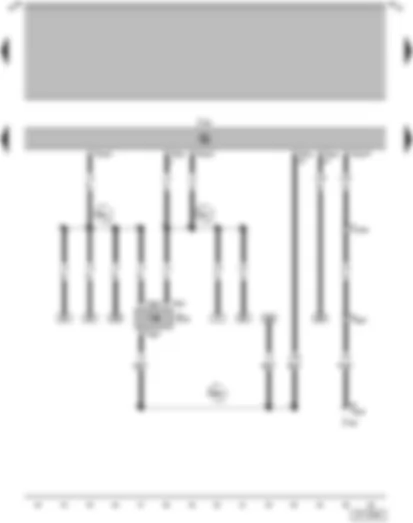
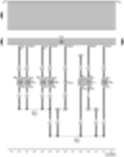
| G186 | Throttle valve drive (electric power control) |
| G187 | Throttle valve drive angle sender -1- (electric power control) |
| G188 | Throttle valve drive angle sender -2- (electric power control) |
| J338 | Throttle valve control unit |
| J537 | 4LV (injection system) control unit |
| N152 | Ignition transformer |
| P | Spark plug connector |
| Q | Spark plug |
| T4w | 4-pin connector, on ignition transformer |
| T6x | 6-pin connector, on throttle valve control unit |
| T40a | 40-pin connector, on 4LV (injection system) control unit |
| G2 | Coolant temperature sender |
| G40 | Hall sender |
| G42 | Intake air temperature sender |
| G62 | Coolant temperature sender |
| G71 | Air mass meter |
| J537 | 4LV (injection system) control unit |
| T3q | Conector de encaixe, triplo, no transmissor hall |
| T4j | 4-pin connector, on intake manifold pressure sender |
| T4k | 4-pin connector, on coolant temperature sender |
| T10g | 10-pin connector, (black) behind shelf - front passenger's side |
| T40a | 40-pin connector, on 4LV (injection system) control unit |
| T81a | 81-pin connector, on 4LV (injection system) control unit |
| 339 | Earth connection (sender earth), in injection system wiring harness |
| E46 | Positive connection -1- (5 Volt), in injection system wiring harness |
| G28 | Engine speed sender |
| G39 | Lambda probe |
| G79 | Accelerator pedal position sender |
| G185 | Accelerator pedal position sender -2- |
| J537 | 4LV (injection system) control unit |
| T3s | 3-pin connector, near starter |
| T4i | 4-pin connector, in engine compartment, rear |
| T6h | 6-pin connector, on accelerator pedal position sender |
| T8l | 8-pin connector, behind steering column trim |
| T10e | 10-pin connector, (red) behind shelf - front passenger's side |
| T40a | 40-pin connector, on 4LV (injection system) control unit |
| T81a | 81-pin connector, on 4LV (injection system) control unit |
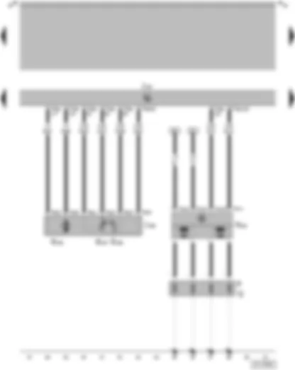
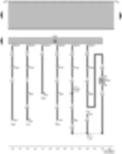
| J17 | Fuel pump relay |
| J537 | 4LV (injection system) control unit |
| N30 | Injector, cylinder 1 |
| N31 | Injector, cylinder 2 |
| N32 | Injector, cylinder 3 |
| N33 | Injector, cylinder 4 |
| N80 | Activated charcoal filter system solenoid valve I (pulsed) |
| T2ar | 2-pin connector, on activated charcoal filter system solenoid valve I |
| T2bd | 2-pin connector, on injector, cylinder 1 |
| T2be | 2-pin connector, on injector, cylinder 2 |
| T2bf | 2-pin connector, on injector, cylinder 3 |
| T2bg | 2-pin connector, on injector, cylinder 4 |
| T9e | 9-pin connector, on fuel pump relay |
| T10e | 10-pin connector, (red) behind shelf - front passenger's side |
| T40a | 40-pin connector, on 4LV (injection system) control unit |
| T81a | 81-pin connector, on 4LV (injection system) control unit |
| E44 | Connection (87, injectors), in injection system wiring harness |
| E45 | Connection (87), in injection system wiring harness |
| F129 | Air conditioner pressure switch |
| F163 | Air conditioner shut-off thermal switch |
| J101 | Radiator fan 2nd speed relay |
| J301 | Air conditioning system control unit |
| J362 | Immobilizer control unit |
| J365 | Air conditioning system switch-off relay |
| J537 | 4LV (injection system) control unit |
| T1ae | Single conector, on A/C Cut-Out Thermal Switch |
| T1af | Single conector, on A/C Cut-Out Thermal Switch |
| T4e | 4-pin connector, on air conditioner pressure switch |
| T6g | 6-pin connector, (grey) next to relay plate |
| T7d | 7-pin connector, on air conditioning system control unit |
| T8g | 8-pin connector, on immobilizer control unit |
| T8k | 8-pin connector, behind dash panel, centre |
| T9c | 9-pin connector, on radiator fan 2nd speed relay |
| T9d | 9-pin connector, on air conditioning system switch-off relay |
| T10f | 10-pin connector, (brown) behind shelf - front passenger's side |
| T81a | 81-pin connector, on 4LV (injection system) control unit |
| A138 | Connection -2-, in dash panel wiring harness |
| L2 | Connection in air conditioner wiring harness |
| F22 | Oil pressure switch (0.3 bar) |
| G1 | Fuel gauge sender |
| G3 | Coolant temperature gauge |
| J285 | Control unit with display in dash panel insert |
| K | Dash panel insert |
| K2 | Alternator warning lamp |
| K3 | Oil pressure warning lamp |
| K132 | Electronic power control fault lamp |
| S227 | Fuse in fuse holder |
| T1x | Single connector, on oil pressure switch (0.3 bar) |
| T10f | 10-pin connector, (brown) behind shelf - front passenger's side |
| T10g | 10-pin connector, (black) behind shelf - front passenger's side |
| T32a | 32-pin connector, on dash panel insert |
| 335 | Earth connection -5-, in dash panel wiring harness |
| E4 | Headlight dipper/flasher switch |
| G | Fuel gauge sender |
| G6 | Fuel pump (pre-supply pump) |
| S8 | Fuse in relay plate fuse box |
| S13 | Fuse in relay plate fuse box |
| S14 | Fuse in relay plate fuse box |
| T1o | Single connector, on lower part of right A-pillar |
| T4g | 4-pin connector, under rear right seat |
| T5b | 5-pin connector, on headlight dipper/flasher switch |
| T6k | 6-pin connector, (lilac) next to relay plate |
| T6q | 6-pin connector, (white) next to relay plate |
| T10g | 10-pin connector, (black) behind shelf - front passenger's side |
| 44 | Earth point, lower part of left A-pillar |
| A1 | Positive connection (30a), in dash panel wiring harness |
| A164 | Positive connection -2- (30a), in dash panel wiring harness |


 Deutsch
 English
 Español
 Français
 Nederlands
 Русский

