ENGINE PERFORMANCE
5.2L
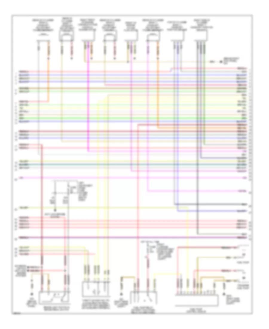
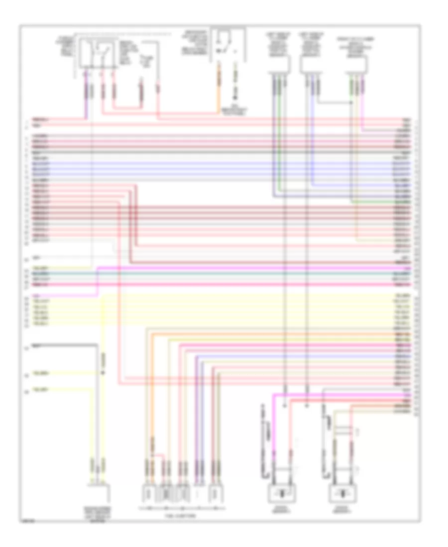
5.2L, Engine Performance Wiring Diagram (1 of 8) for Audi S8 Quattro 2009

List of elements for 5.2L, Engine Performance Wiring Diagram (1 of 8) for Audi S8 Quattro 2009:
- (behind right kick panel) g43
- (left rear of engine) evaporative emission (evap) canister purge solenoid valve 2
- (right front of engine compt) mass air flow (maf)/intake air temperature (iat) sensor
- (top rear of cylinder bank 1) low fuel pressure sensor
- (under accelerator pedal) kick down switch
- Anti-theft system starting/ charging system
- Brake booster pressure sensor
- Comfort system central control module (right side of luggage compt)
- Cooling fans system
- Cruise control system
- Engine control module (ecm) i (right rear of engine compt)
- Exhaust flap valve 1
- G44 (behind left kick panel)
- Heated oxygen sensor (downstream of 3-way catalytic converter)
- Heated oxygen sensor 2 (upstream of exhaust catalytic converter)
- Intake air switch- over valve (right front of eng compt)
- Map controlled engine cooling thermostat
- Nca
- Oxygen sensor (downstream of 3-way catalytic converter (twc))
- Oxygen sensor 2 (downstream of 3-way catalytic converter (twc))
- Starting/ charging system
- T94a
- Transmissions system
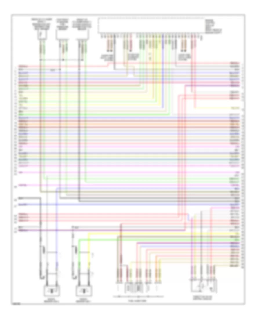
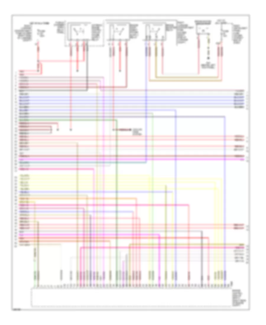
5.2L, Engine Performance Wiring Diagram (2 of 8) for Audi S8 Quattro 2009
List of elements for 5.2L, Engine Performance Wiring Diagram (2 of 8) for Audi S8 Quattro 2009:
- (behind right kick panel) g43
- (front of engine) intake flap motor
- (rear of cylinder bank 1) camshaft adjustment valve 1
- (rear of cylinder bank 1) camshaft adjustment valve 1 (exhaust)
- (rear of cylinder bank 2)
- (rear of cylinder bank 2) camshaft adjustment valve 2 (exhaust)
- (right front of engine) variable intake manifold runner motor
- (right side of cylinder bank 1) camshaft position sensor 3
- (top of cylinder bank 1) camshaft position sensor
- 22a
- Anti-lock brakes system
- Brake-light switch & brake pedal switch
- Camshaft adjustment valve 2
- Exterior lights & anti-lock brakes systems
- Fuel pump
- Fuel pump control module
- Fuel pump relay (on right kick panel relay & fuse panel)
- Fuse 40a
- Fuse 5a
- G44 (behind left kick panel)
- G51 (right rear of luggage compt)
- G675 (right side of luggage compt)
- Hot at all time
- Left instrument panel fuse holder (in left end of dash)
- Right luggage compartment fuse holder (right side of luggage compt)
- Throttle position (tp) & accelerator pedal position (app) sender 2 (on accelerator pedal)
- Transfer fuel pump
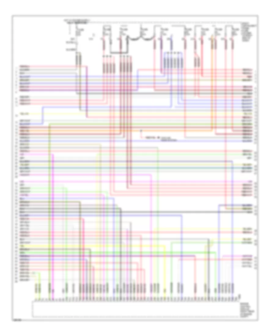
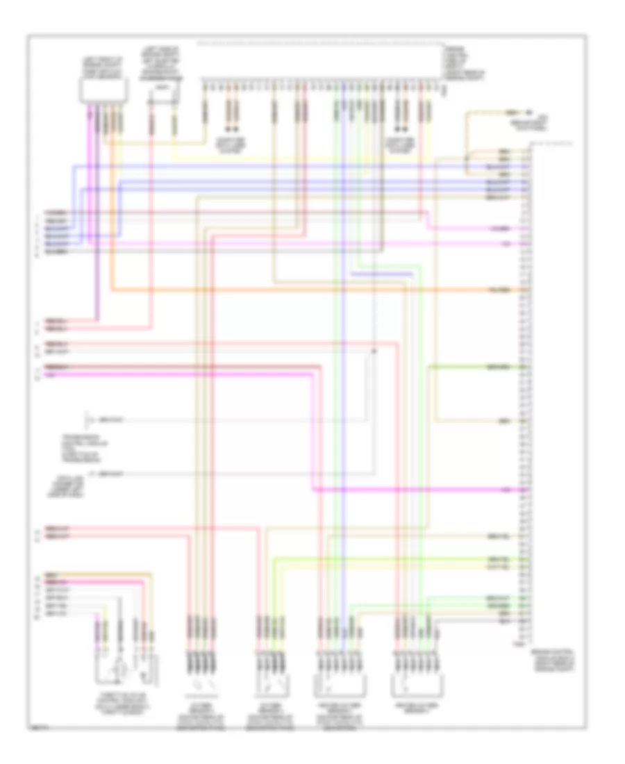
5.2L, Engine Performance Wiring Diagram (3 of 8) for Audi S8 Quattro 2009
List of elements for 5.2L, Engine Performance Wiring Diagram (3 of 8) for Audi S8 Quattro 2009:
- (front of cylinder bank 1) intake manifold runner position sensor
- (rear of cylinder bank 1) engine coolant temperature (ect) sensor
- (top front of engine) fuel pressure sensor
- Computer data lines system
- Engine control module (ecm) (right rear of engine compt)
- Fuel injectors
- Knock sensor (ks) 1
- Knock sensor (ks) 2
- Nca
- Starting/ charging system
- T94a
- Throttle valve control module
5.2L, Engine Performance Wiring Diagram (4 of 8) for Audi S8 Quattro 2009
List of elements for 5.2L, Engine Performance Wiring Diagram (4 of 8) for Audi S8 Quattro 2009:
- 28a
- 31a
- Cooling fans system
- Engine control module (right rear of engine compt)
- Fuse 10a
- Fuse 15a
- Fuse 30a
- Fuse 40a
- Fuse 5a
- Nca
- Red
- Right instrument panel fuse holder (in right end of dash)
- T60a
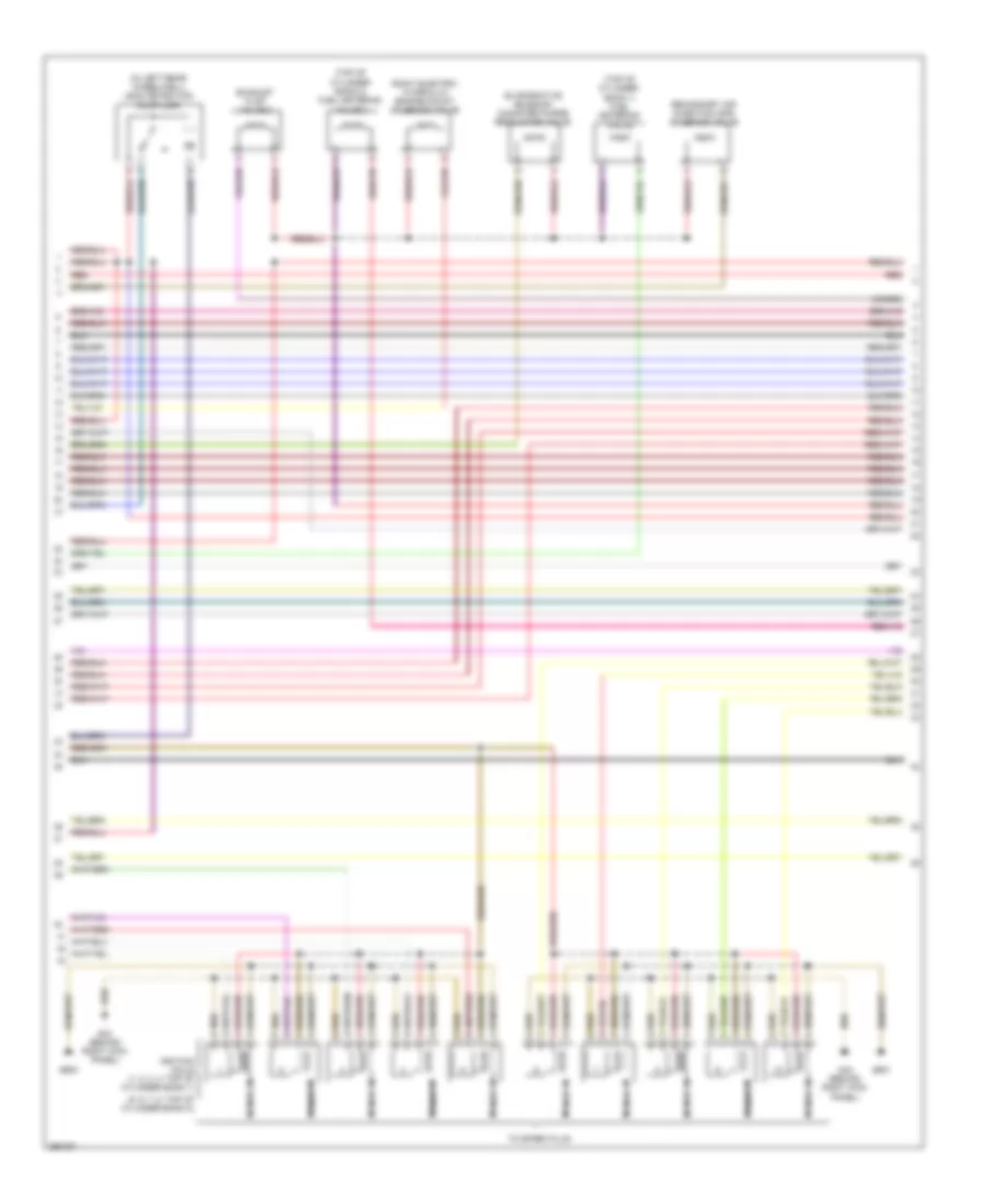
5.2L, Engine Performance Wiring Diagram (5 of 8) for Audi S8 Quattro 2009
List of elements for 5.2L, Engine Performance Wiring Diagram (5 of 8) for Audi S8 Quattro 2009:
- (5, 6, 7, 8: top of cylinder bank 2)
- (in left rear wheelwell) leak detection pump (ldp)
- (top of cylinder bank 1) fuel metering valve
- (top of cylinder bank 2) fuel metering valve 2
- Evaporative emission canister purge regulator valve
- Exhaust flap valve 2
- G43 (behind right kick panel)
- G600
- G601
- Ignition coils (1, 2, 3, 4: top of cylinder bank 1)
- Nca
- Red
- Right electro- hydraulic engine mount solenoid valve
- Secondary air injection (sir) solenoid valve
- To spark plug
5.2L, Engine Performance Wiring Diagram (6 of 8) for Audi S8 Quattro 2009
List of elements for 5.2L, Engine Performance Wiring Diagram (6 of 8) for Audi S8 Quattro 2009:
- (front of cylinder bank 2) intake manifold runner sensor 2
- (left side of cylinder bank 2) camshaft position sensor 2
- (left side of cylinder bank 2) camshaft position sensor 4
- Engine speed (rpm) sensor (left rear of engine)
- Fuel injectors
- Fuse 50a
- G43 (behind right kick panel)
- Knock sensor 3
- Knock sensor 4
- Nca
- Plenum chamber e-box relay panel
- Red
- Secon- dary air injection (air) pump relay
- Secondary air injection (air) pump motor (below right long member)
5.2L, Engine Performance Wiring Diagram (7 of 8) for Audi S8 Quattro 2009
List of elements for 5.2L, Engine Performance Wiring Diagram (7 of 8) for Audi S8 Quattro 2009:
- 40a
- Brake booster relay
- Brake system vacuum pump
- Cooling fans system
- Engine control module (ecm) 2 (right rear of engine compt)
- Fuse 150a
- Fuse 15a
- G44 (behind left kick panel)
- Hot at all times
- Plenum chamber e-box relay panel
- Red
- Right instrument panel fuse holder (in right end of dash)
- Right luggage compartment fuse holder (right side of luggage compt)
- T60d
5.2L, Engine Performance Wiring Diagram (8 of 8) for Audi S8 Quattro 2009
List of elements for 5.2L, Engine Performance Wiring Diagram (8 of 8) for Audi S8 Quattro 2009:
- (left front of engine compt) mass air flow (maf) sensor 2
- (left side of engine compt) left electro- hydraulic engine mount solenoid valve
- Computer data lines system
- Data link connector (under left side of dash)
- Engine control module (ecm) 2 (right rear of engine compt)
- G43 (behind right kick panel)
- Heated oxygen sensor 3 (downstream of 3-way catalytic converter)
- Heated oxygen sensor 4
- Nca
- Oxygen sensor 3 (downstream of 3-way catalytic converter (twc))
- Oxygen sensor 4 (downstream of 3-way catalytic converter (twc))
- T94d
- Throttle valve control module 2 (on cylinder bank 2 throttle body)
- Transmission control module (tcm) (in bottom of transmission)