ENGINE PERFORMANCE
2.5L
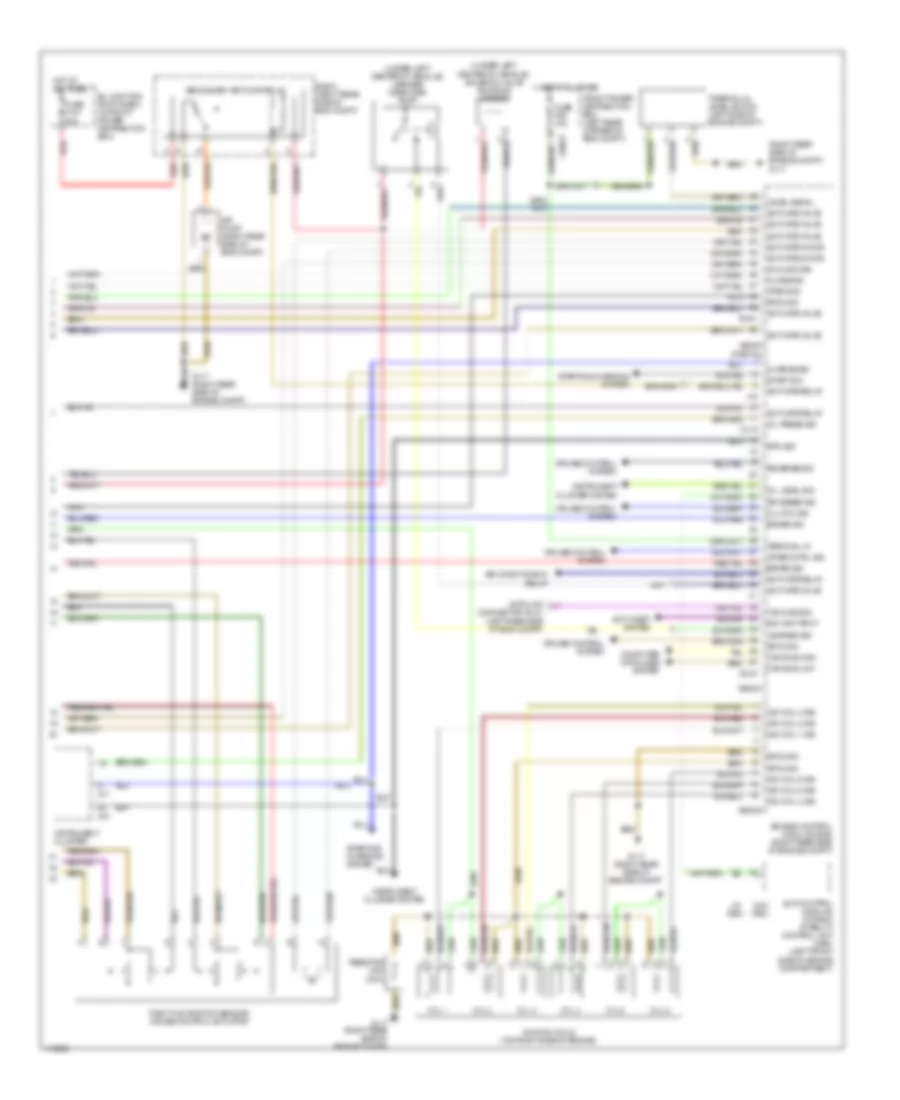
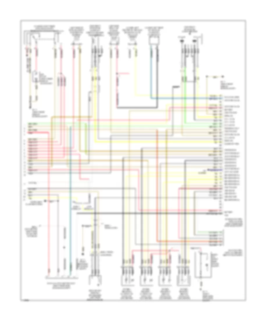
2.5L, Engine Performance Wiring Diagram (1 of 3) for BMW Z3 1999

List of elements for 2.5L, Engine Performance Wiring Diagram (1 of 3) for BMW Z3 1999:
- (right rear side of engine compt)
- (right rear side of engine compt) g117
- (under rear storage compt) g311
- 2-3
- 8-11
- Activate relay
- Activate valve
- Air mass met
- B+ junction point e-box (in front power distribution box)
- Camshaft position sensor 1 (inlet) (on front of engine)
- Camshaft position sensor 2 (outlet) (on front of engine)
- Camshft sig
- Can bus high
- Can bus low
- Characteristic map cooling thermostat (on front of cylinder head)
- Charging sig
- Crankshaft position/ rpm sensor (on front of engine)
- Crnkshft sig
- Cyl 1-3
- Cyl 1-3 ks
- Cyl 1-6 fuel pump relay
- Cyl 4-6 ks
- Cyl 4-6 nca
- Diagnosis
- E-box
- E-box (right rear side of eng compt)
- Engine control module (dme) (right rear side of engine compt)
- Engine control module relay
- Engine coolant temperature sensor (on front of engine)
- Front power distribution box (left rear corner of eng compt)
- Fuel pump (in fuel tank)
- Fuse f18 15a
- Fuse f202 30a
- Fuse f203 20a
- Fuse f204 30a
- Ground
- Hot at all times
- Hot film air mass meter (on left side of eng compt, on air intake tube)
- Intake air temperature sensor (on top center of eng, on intake manifold)
- Knock sensor (left side of engine)
- Nca
- O2s htd sig
- O2s htg sig
- Oil pressure switch (left side of engine)
- Oil temperature sensor (right side of oil filter)
- Press sig
- Red
- Sensor sig
- Sig ground
- Start sig
- Starting/ charging system
- Temp sig
- Tp sig
- Transmission control module (egs) (right rear side of engine compt, in e-box)
- X10016
- X60001
- X60002
- X60003 (partial)
- X64101
- X64102
- X8680
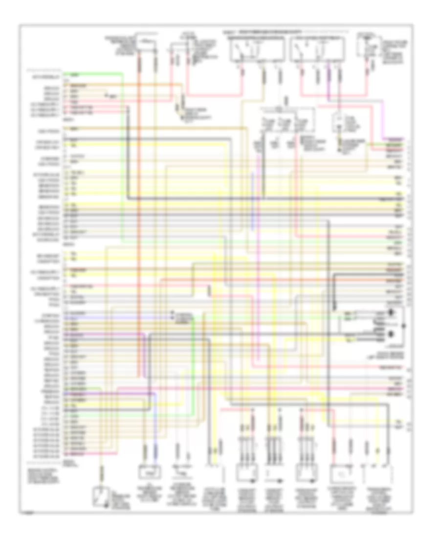
2.5L, Engine Performance Wiring Diagram (2 of 3) for BMW Z3 1999
List of elements for 2.5L, Engine Performance Wiring Diagram (2 of 3) for BMW Z3 1999:
- Brakelight switch (on bracket, above brake pedal)
- Cyl 1
- Cyl 2
- Cyl 3
- Cyl 4
- Cyl 5
- Cyl 6
- E-box (right rear side of eng compt)
- Evaporative emission valve (left side of engine compartment)
- Exterior lights system
- Front power distribution box (left rear corner of eng compt)
- Fuel injection valves
- Fuse f13 7.5a
- Fuse f205 30a
- Fuse f46 15a
- G117 (right rear side of eng compt)
- Hot at all times
- Hot in accy, run or start
- Hot in run or start
- Idle speed control valve (front of engine)
- Individual control intake system valve (left side of engine compartment)
- Nca
- Oxygen sensor 1 (behind catalytic converter)
- Oxygen sensor 1 (in front of catalytic converter)
- Oxygen sensor 2 (behind catalytic converter)
- Oxygen sensor 2 (in front of catalytic converter)
- Red
- Secondary air pump valve (left front of engine)
- Unloader relay terminal 15
- Variable camshaft control valve 1 (inlet) (front left side of cylinder head)
- Variable camshaft control valve 2 (outlet) (front left side of cylinder head)
- X10018
- X9680
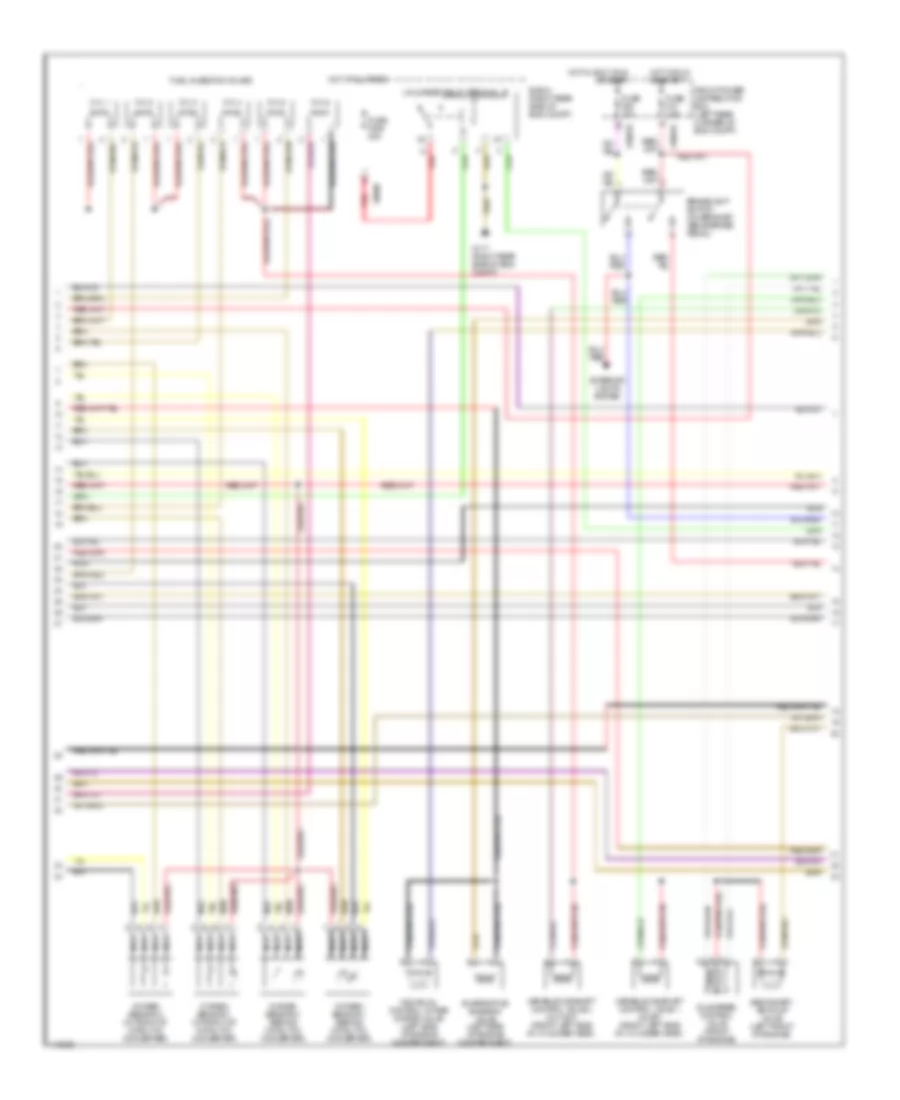
2.5L, Engine Performance Wiring Diagram (3 of 3) for BMW Z3 1999
List of elements for 2.5L, Engine Performance Wiring Diagram (3 of 3) for BMW Z3 1999:
- (right rear side of engine compt) g117
- (under left center of vehicle) leakage diagnosis pump
- (under left center of vehicle) solenoid valve (running losses)
- (w/ dsc)
- (w/o dsc)
- 12-16
- 38-40
- 4-9
- 50-51
- Activate motor
- Activate relay
- Activate valve
- Air conditioning relay
- Air pump (right rear side of eng compt)
- Anti-theft system
- B+ junction point e-box (in front power distribution box)
- Brake sig
- Can bus high
- Can bus low
- Charge sig
- Close sig
- Clutch sig
- Computer data lines system
- Cooling sig
- Crse cntrl sig
- Cruise control system
- Cyl 1
- Cyl 2
- Cyl 3
- Cyl 4
- Cyl 5
- Cyl 6
- Data link connector (dlc) (left rear side of eng compt)
- Drv awy prot
- E-box (right rear side of eng compt)
- Engine control module (dme) (right rear side of engine compt)
- Front power distribution box (left rear corner of eng compt)
- Fuse f107 50a
- Fuse f26 10a
- G117 (right rear side of engine compt)
- Ground
- Hot at all times
- Ign coil 1 sig
- Ign coil 2 sig
- Ign coil 3 sig
- Ign coil 4 sig
- Ign coil 5 sig
- Ign coil 6 sig
- Ignition coils (top right side of engine)
- Instrument cluster
- Instrument cluster system
- Leakage sig
- Level signal
- Nca
- Oil level sig
- Oil press sig
- Open sig
- Red
- Resistor (240 ohm)
- Reverse sig
- Rpm sig
- Rr speed sig
- Secondary air pump relay
- Slip control module/ dynamic stability control unit (dsc) (left front side of engine compartment)
- Start sig
- Starting/ charging system
- Starting/charging system
- Terminal 15
- Thermal oil level switch (left side of engine compt)
- Throttle position sensor/ cruise control actuator
- Txd diag sig
- X10017
- X16
- X17
- X60003 (partial)
- X60004
- X60005
2.8L
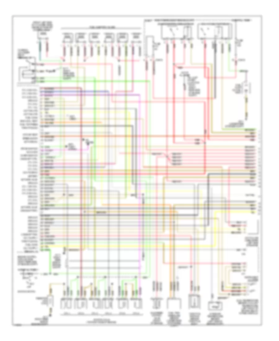
2.8L, Engine Performance Wiring Diagram (1 of 3) for BMW Z3 1999
List of elements for 2.8L, Engine Performance Wiring Diagram (1 of 3) for BMW Z3 1999:
- (right rear side of engine compt)
- (right rear side of engine compt) g117
- (under rear storage compt) g311
- 2-3
- 8-11
- Activate relay
- Activate valve
- Air mass met
- B+ junction point e-box (in front power distribution box)
- Camshaft position sensor 1 (inlet) (on front of engine)
- Camshaft position sensor 2 (outlet) (on front of engine)
- Camshft sig
- Can bus high
- Can bus low
- Characteristic map cooling thermostat (on front of cylinder head)
- Charging sig
- Crankshaft position/ rpm sensor (on front of engine)
- Crnkshft sig
- Cyl 1-3
- Cyl 1-3 ks
- Cyl 1-6 fuel pump relay
- Cyl 4-6 ks
- Cyl 4-6 nca
- Diagnosis
- E-box
- E-box (right rear side of eng compt)
- Engine control module (dme) (right rear side of engine compt)
- Engine control module relay
- Engine coolant temperature sensor (on front of engine)
- Front power distribution box (left rear corner of eng compt)
- Fuel pump (in fuel tank)
- Fuse f18 15a
- Fuse f202 30a
- Fuse f203 20a
- Fuse f204 30a
- Ground
- Hot at all times
- Hot film air mass meter (on left side of eng compt, on air intake tube)
- Intake air temperature sensor (on top center of eng, on intake manifold)
- Knock sensor (left side of engine)
- Nca
- O2s htd sig
- O2s htg sig
- Oil pressure switch (left side of engine)
- Oil temperature sensor (right side of oil filter)
- Press sig
- Red
- Sensor sig
- Sig ground
- Start sig
- Starting/ charging system
- Temp sig
- Tp sig
- Transmission control module (egs) (right rear side of engine compt, in e-box)
- X10016
- X60001
- X60002
- X60003 (partial)
- X64101
- X64102
- X8680
2.8L, Engine Performance Wiring Diagram (2 of 3) for BMW Z3 1999
List of elements for 2.8L, Engine Performance Wiring Diagram (2 of 3) for BMW Z3 1999:
- Brakelight switch (on bracket, above brake pedal)
- Cyl 1
- Cyl 2
- Cyl 3
- Cyl 4
- Cyl 5
- Cyl 6
- E-box (right rear side of eng compt)
- Evaporative emission valve (left side of engine compartment)
- Exterior lights system
- Front power distribution box (left rear corner of eng compt)
- Fuel injection valves
- Fuse f13 7.5a
- Fuse f205 30a
- Fuse f46 15a
- G117 (right rear side of eng compt)
- Hot at all times
- Hot in accy, run or start
- Hot in run or start
- Idle speed control valve (front of engine)
- Individual control intake system valve (left side of engine compartment)
- Nca
- Oxygen sensor 1 (behind catalytic converter)
- Oxygen sensor 1 (in front of catalytic converter)
- Oxygen sensor 2 (behind catalytic converter)
- Oxygen sensor 2 (in front of catalytic converter)
- Red
- Secondary air pump valve (left front of engine)
- Unloader relay terminal 15
- Variable camshaft control valve 1 (inlet) (front left side of cylinder head)
- Variable camshaft control valve 2 (outlet) (front left side of cylinder head)
- X10018
- X9680
2.8L, Engine Performance Wiring Diagram (3 of 3) for BMW Z3 1999
List of elements for 2.8L, Engine Performance Wiring Diagram (3 of 3) for BMW Z3 1999:
- (right rear side of engine compt) g117
- (under left center of vehicle) leakage diagnosis pump
- (under left center of vehicle) solenoid valve (running losses)
- (w/ dsc)
- (w/o dsc)
- 12-16
- 38-40
- 4-9
- 50-51
- Activate motor
- Activate relay
- Activate valve
- Air conditioning relay
- Air pump (right rear side of eng compt)
- Anti-theft system
- B+ junction point e-box (in front power distribution box)
- Brake sig
- Can bus high
- Can bus low
- Charge sig
- Close sig
- Clutch sig
- Computer data lines system
- Cooling sig
- Crse cntrl sig
- Cruise control system
- Cyl 1
- Cyl 2
- Cyl 3
- Cyl 4
- Cyl 5
- Cyl 6
- Data link connector (dlc) (left rear side of eng compt)
- Drv awy prot
- E-box (right rear side of eng compt)
- Engine control module (dme) (right rear side of engine compt)
- Front power distribution box (left rear corner of eng compt)
- Fuse f107 50a
- Fuse f26 10a
- G117 (right rear side of engine compt)
- Ground
- Hot at all times
- Ign coil 1 sig
- Ign coil 2 sig
- Ign coil 3 sig
- Ign coil 4 sig
- Ign coil 5 sig
- Ign coil 6 sig
- Ignition coils (top right side of engine)
- Instrument cluster
- Instrument cluster system
- Leakage sig
- Level signal
- Nca
- Oil level sig
- Oil press sig
- Open sig
- Red
- Resistor (240 ohm)
- Reverse sig
- Rpm sig
- Rr speed sig
- Secondary air pump relay
- Slip control module/ dynamic stability control unit (dsc) (left front side of engine compartment)
- Start sig
- Starting/ charging system
- Starting/charging system
- Terminal 15
- Thermal oil level switch (left side of engine compt)
- Throttle position sensor/ cruise control actuator
- Txd diag sig
- X10017
- X16
- X17
- X60003 (partial)
- X60004
- X60005
3.2L
3.2L, Engine Performance Wiring Diagram (1 of 2) for BMW Z3 1999
List of elements for 3.2L, Engine Performance Wiring Diagram (1 of 2) for BMW Z3 1999:
- (front left side of cylinder head) variable camshaft control valve 1
- (in e-box) unloader relay terminal 15
- (not used)
- (right rear side of engine compt)
- A/c on sig
- A/c system
- Acc
- Activate a/c
- Activate valve
- Anti- theft system
- B+ jump start junction point (right rear side of engine compt)
- Battery
- Camshaft ctrl
- Camshaft pos
- Chekc eng ind
- Crnkshft rpm
- Cyl 1
- Cyl 1 ign coil
- Cyl 1 inj
- Cyl 1-6 fuel pump relay
- Cyl 2
- Cyl 2 ign coil
- Cyl 2 inj
- Cyl 3
- Cyl 3 ign coil
- Cyl 3 inj
- Cyl 4
- Cyl 4 ign coil
- Cyl 4 inj
- Cyl 5
- Cyl 5 ign coil
- Cyl 5 inj
- Cyl 6
- Cyl 6 ign coil
- Cyl 6 inj
- Drive-away sig
- Dual temperature sensor (coolant temperature) (left front of engine, below intake manifold)
- E-box
- Eng cool temp
- Engine control module (dme) (right rear side of engine compt)
- Engine control module relay
- Fuel cons
- Fuel injection valves
- Fuel pump (in fuel tank)
- Fuel tank pressure sensor (under rear of storage compt)
- Fuel tnk press
- Fuse f13 5a
- Fuse f18 15a
- G117 (right rear side of engine compt)
- G311 (under rear storage compt)
- Ground
- Hot at all times
- Hot fam mtr
- Hot film air mass meter (left side of engine)
- Idle speed control valve (front of engine)
- Ignition coils (top right side of engine)
- Ignition switch
- Instrument cluster
- Intake air temperature sensor (left side of engine compt)
- Intk air temp
- Nca
- Off
- Red
- Resistor (240 ohm)
- Run
- Speed sig rr
- Start
- Terminal 15
- Throt pos sig
- Throttle pos
- Throttle position sensor (throttle body)
- X10016
- X16
- X17
3.2L, Engine Performance Wiring Diagram (2 of 2) for BMW Z3 1999
List of elements for 3.2L, Engine Performance Wiring Diagram (2 of 2) for BMW Z3 1999:
- (early prod)
- (in e-box, right rear of engine compt) secondary air pump relay
- (late prod)
- (left side front of engine) secondary air pump valve
- (left side of engine compt) evaporative emission valve
- (top front of engine) camshaft position sensor (cylinder id)
- (top front of engine) knock sensor
- (under left center of vehicle) solenoid valve (running losses)
- (under left rear of vehicle) charcoal filter shut off valve
- 02s htg gnd
- 02s sig gnd
- A/c system
- Activate relay
- Activate valve
- Actv a/c comp
- Air pump (right rear side of eng compt)
- Asc-sig mcr
- Asc-sig za
- Asc-sig zwv
- B+ jump start junction point
- Battery
- Camshaft pos
- Crankshaft position/ rpm sensor (left rear side of engine)
- Cyl 1-3
- Cyl 1-3 ks
- Cyl 4-6
- Cyl 4-6 ks
- Data link connector (dlc) (right rear side of engine compt)
- E-box fan (right rear of eng compt)
- Early product
- Early production
- Engine control module (dme) (right rear side of engine compt)
- G117 (right rear side of engine compt)
- Ground
- Instrument cluster system
- Late product
- Nca
- Obd ii connector (right side of center console)
- Oxygen sensor 1 (behind catalytic converter)
- Oxygen sensor 1 (in front of catalytic converter)
- Oxygen sensor 2 (behind catalytic converter)
- Oxygen sensor 2 (in front of catalytic converter)
- Program volt
- Red
- Running loss
- Sensor signal
- Slip control module (abs/asc) (behind glove box)
- Txd