ENGINE PERFORMANCE
4.2L
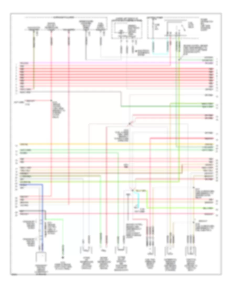
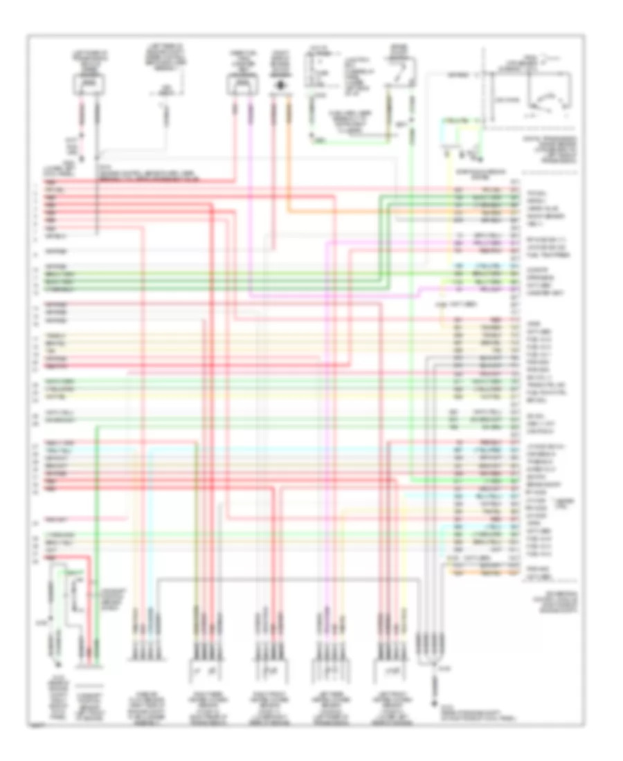
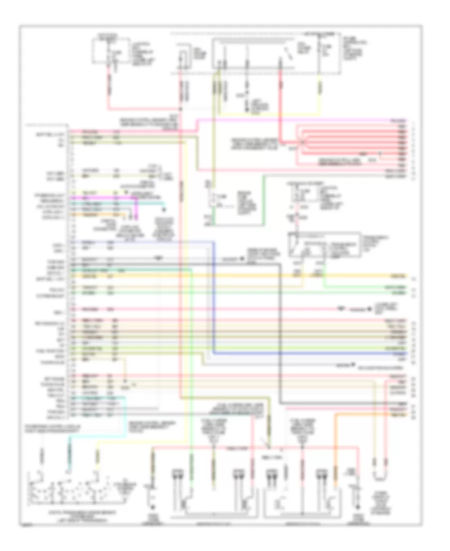
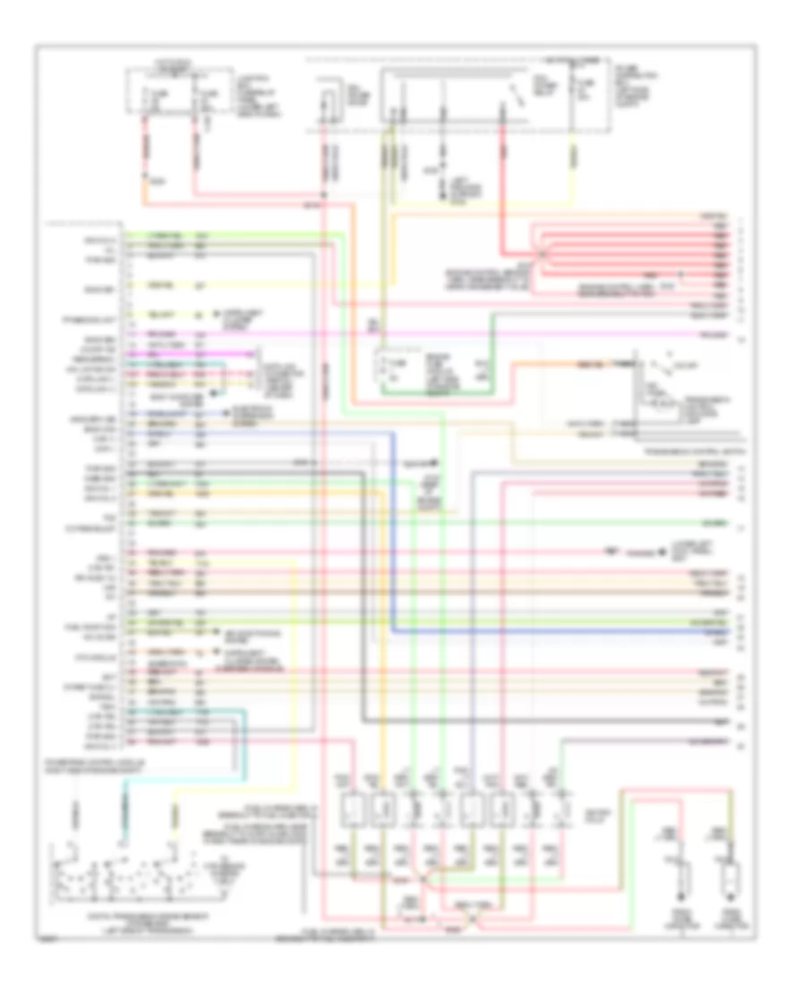
4.2L, Engine Performance Wiring Diagrams, Early Production (1 of 4) for Ford Pickup F250 1997

List of elements for 4.2L, Engine Performance Wiring Diagrams, Early Production (1 of 4) for Ford Pickup F250 1997:
- (engine control harn, near breakout to pcm)
- (engine control sensor harn, near breakout to g123)
- (engine control sensor harn, near breakout to g123) s134
- (engine control sensor harn, near breakout to vapor management valve)
- (fuel charge harn, in breakout to intake runner control monitor)
- (fuel charge harn, near breakout to radio noise capacitor)
- (left radiator support) g108
- (lower left cowl panel) g201
- (partial 16-pin connector)
- 4x4 hi/low indicator switch & generic electronic module
- 4x4 low ind sw
- 820 ohms
- Accs
- Air conditioning system
- C243
- Case gnd
- Ckp(+)
- Ckp(-)
- Data link (+)
- Data link (-)
- Data link connector (below center of i/p)
- Ect
- Ect gauge
- Engine fuse module (left side of engine compt)
- Evr ctrl
- Feps (eprom)
- Fuel pump mon
- Fuse 30a
- Fuse 5a
- G105 (rear of right fender apron)
- G123 (rear of engine compt, right side of cowl panel)
- Hot at all times
- Hot in run or start
- Iat
- Ign coil 1
- Ign coil 2
- Ignition coil (top of engine)
- Imrc 1
- Imrc 2
- Intake manifold runner control (top front of engine)
- Intake manifold runner control monitor 1 (rear of engine)
- Intake manifold runner control monitor 2 (right side of engine)
- Junction box fuse/relay panel (under left side of i/p)
- Maf
- Mil
- Nca
- Not used
- O/d off
- Octane adjust
- Pcm power diode
- Pcm power relay
- Power distribution box (left side of engine compt)
- Powertrain control module (right side of engine compt)
- Pwr gnd
- Radio noise capacitor
- Red
- Red/ s225
- Rr ho2s sig (12)
- S100
- S103
- S106
- S107
- S116 (engine control sensor harn, near breakout to engine fuse module)
- S117
- S127
- S128
- S130
- S132
- S133
- Shift sol 1 (a/t)
- Shift sol 2 (a/t)
- Spark plugs
- Tach out
- Tcs (a/t)
- Tft
- Transmission control indicator lamp
- Transmission control switch (a/t)
- Tuning valve
- Vss (-)
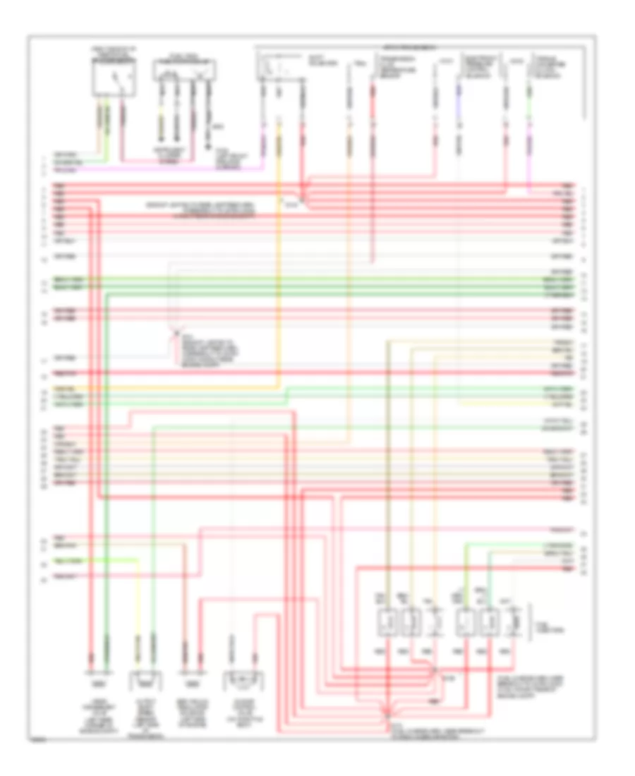
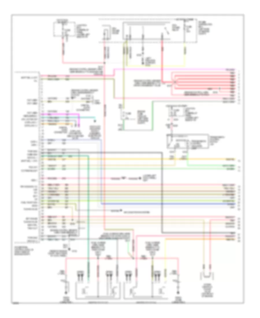
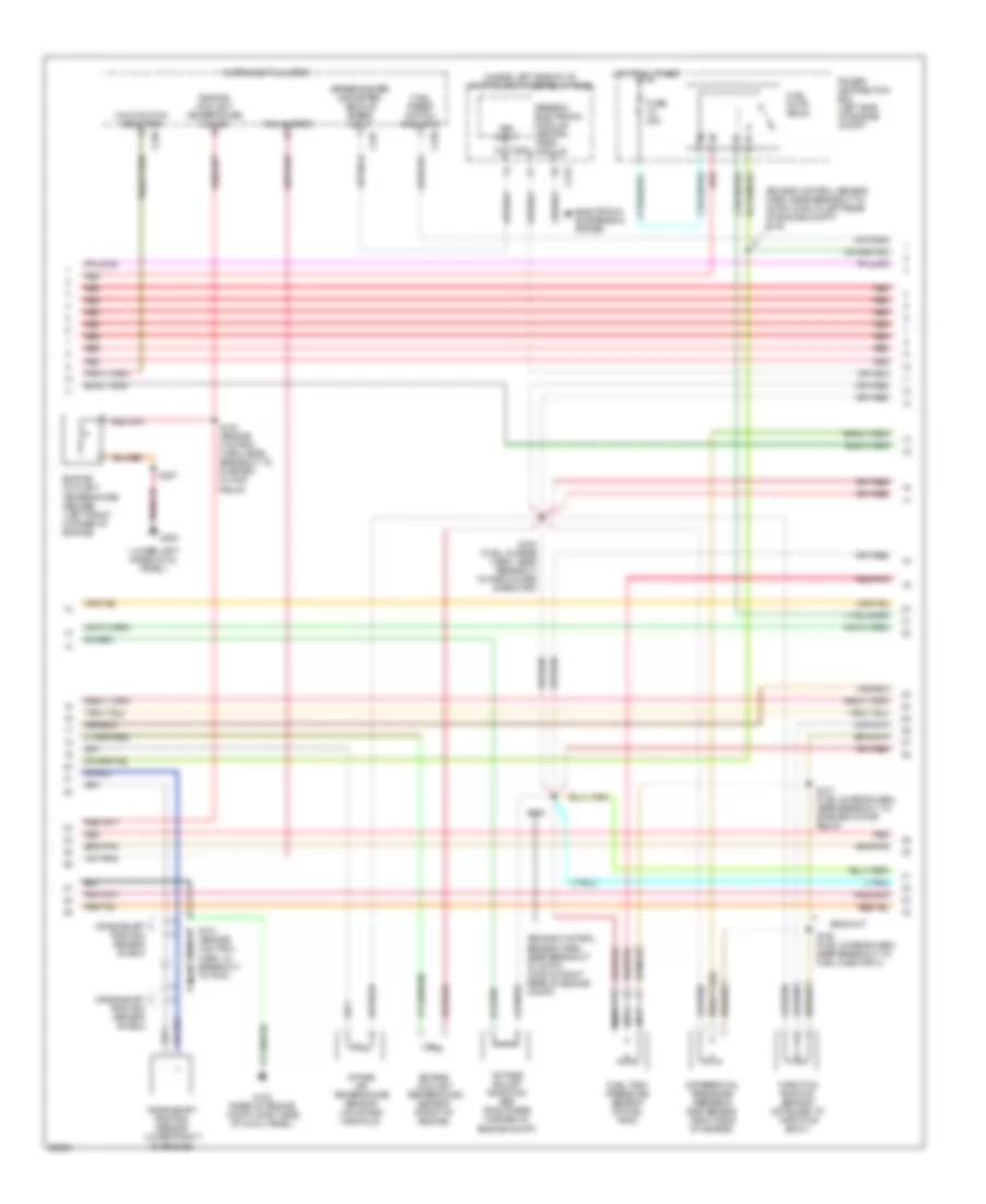
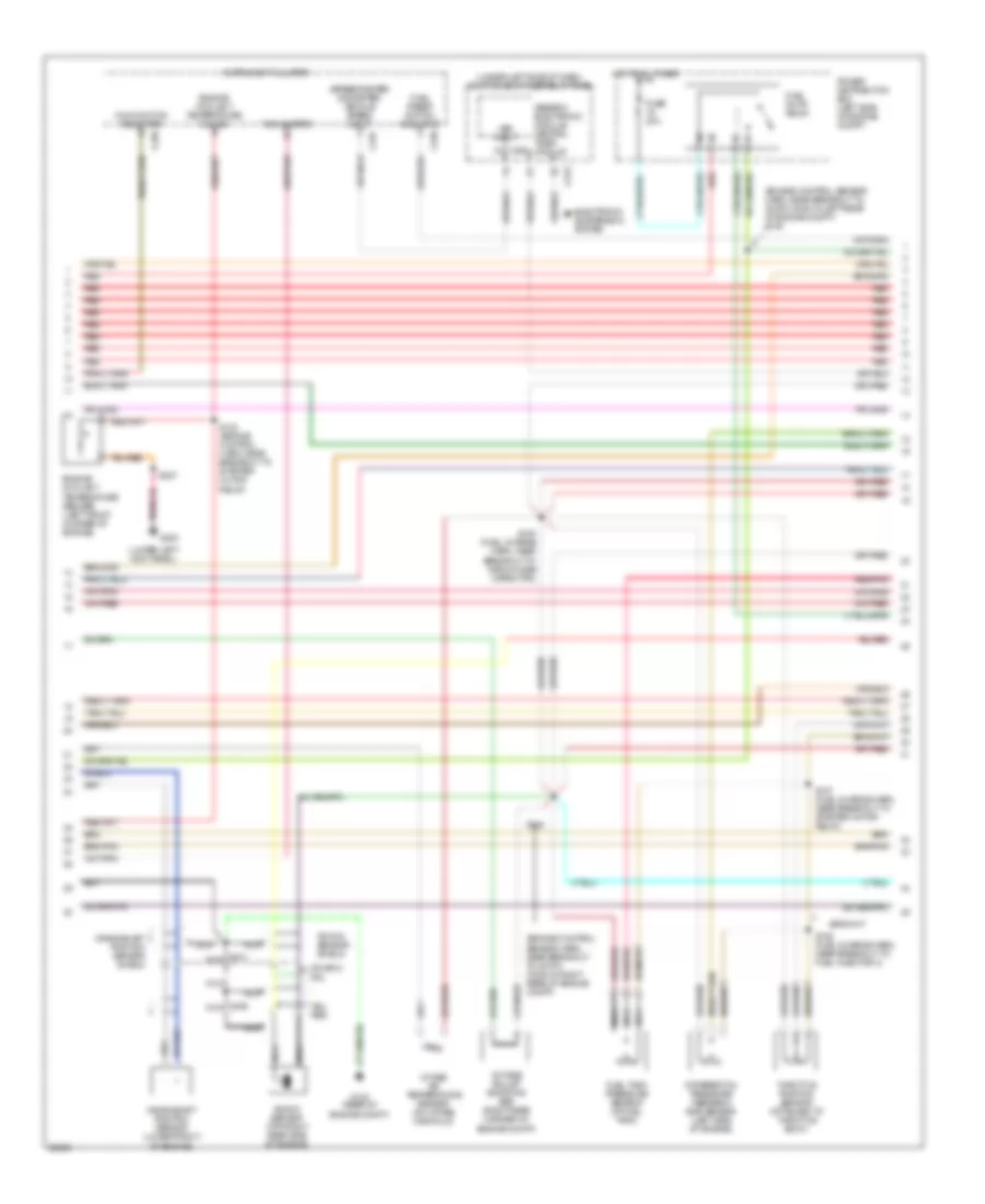
4.2L, Engine Performance Wiring Diagrams, Early Production (2 of 4) for Ford Pickup F250 1997
List of elements for 4.2L, Engine Performance Wiring Diagrams, Early Production (2 of 4) for Ford Pickup F250 1997:
- (engine control sensor harn, near breakout to 35-pin conn in left rear of engine compt) s139
- (engine control sensor harn, near breakout to 38-pin conn in right rear of engine compt)
- (not used)
- (speedometer/ odometer) vehicle speed input
- (under left side of i/p) junction box fuse/relay panel
- C120
- C236
- C237
- C243
- C267
- Crankshaft position sensor (lower front of engine)
- Crankshaft position sensor shield
- Differential pressure feedback egr sensor (right side of engine)
- Electronic suspension system
- Engine coolant temperature gauge
- Engine coolant temperature sensor (front of engine)
- Fuel pump relay
- Fuel reset switch indicator
- Fuel tank pressure sensor (at fuel tank)
- Fuse 20a
- G123 (rear of engine compt, right side of cowl panel)
- Generic electronic module/ central timer module
- Hot at all times
- Instrument cluster
- Intake air temperature sensor (on intake manifold)
- Malfunction indicator
- Nca
- Octane adjust shorting bar (right rear corner of engine compt)
- Power distribution box (left side of engine compt)
- Red
- Red/pnk
- S101 (engine control harn, in breakout to pcm)
- S123 (engine control harn, near breakout to starter motor relay)
- S135 (fuel charge harn, near breakout to radio noise capacitor)
- S136 (fuel charge harn, near breakout to fuel injector 3)
- S137 (fuel charge harn, near breakout to starter motor relay)
- S138
- Tachometer
- Throttle position sensor (attached to throttle body)
- Vss input
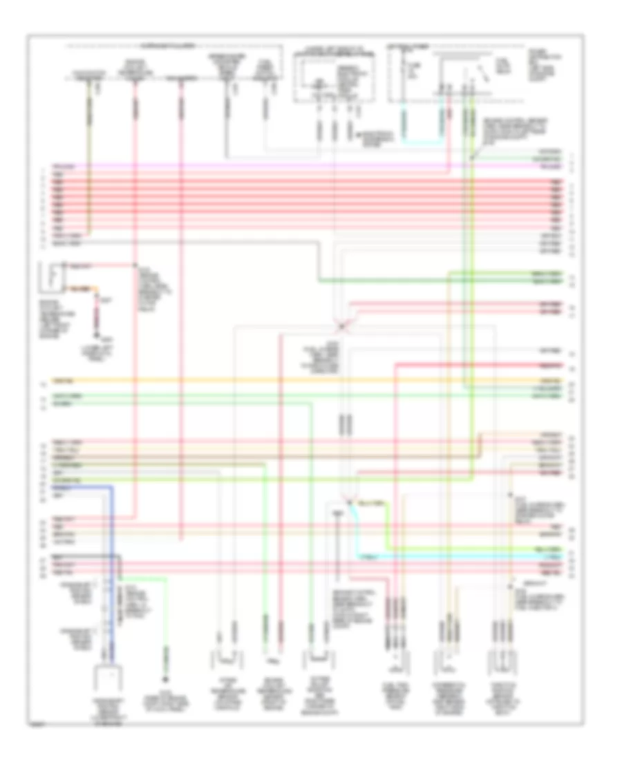
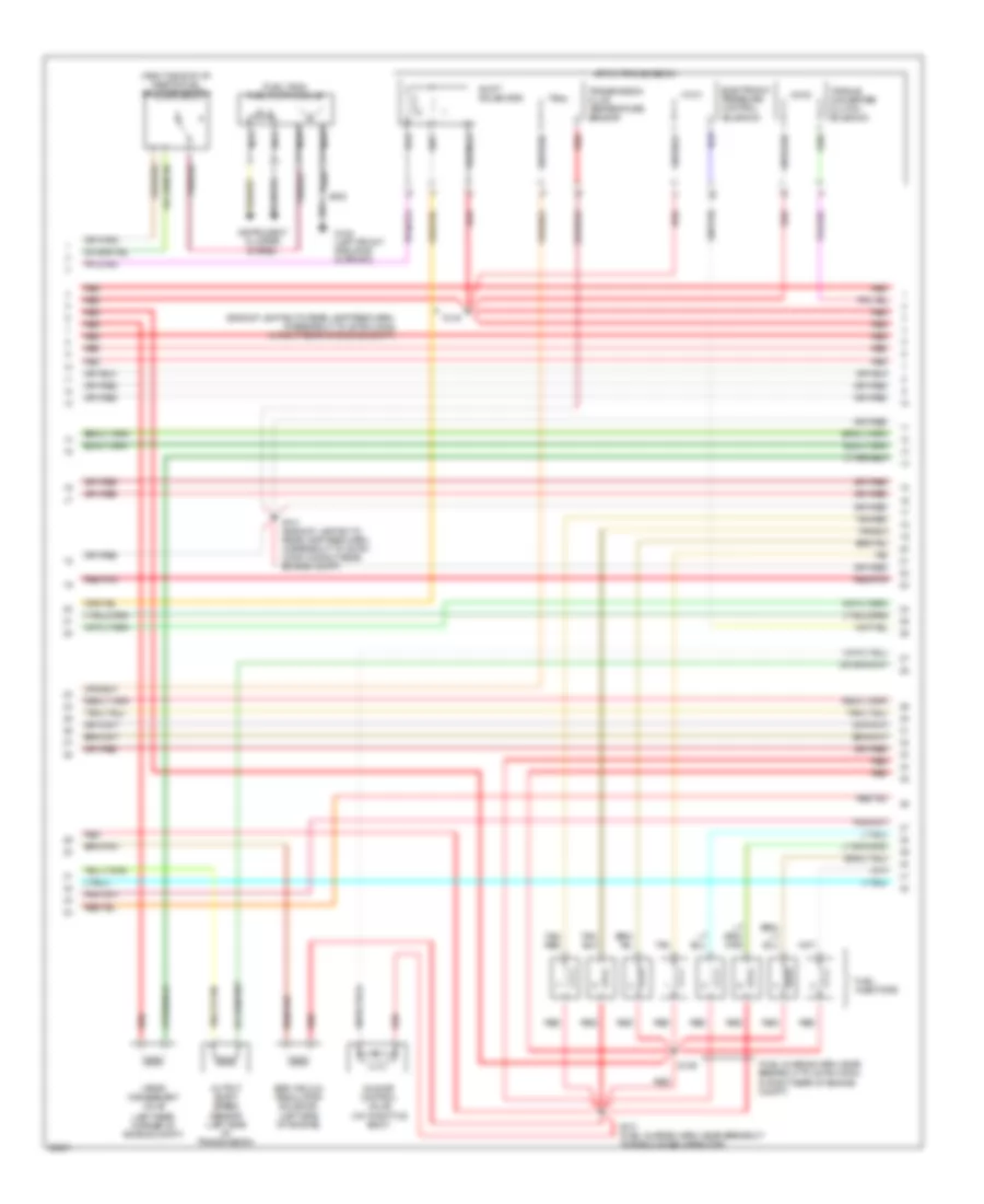
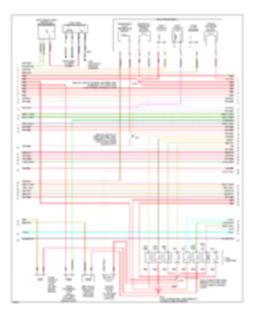
4.2L, Engine Performance Wiring Diagrams, Early Production (3 of 4) for Ford Pickup F250 1997
List of elements for 4.2L, Engine Performance Wiring Diagrams, Early Production (3 of 4) for Ford Pickup F250 1997:
- (backup lamp sw to rear lamp feed harn, at breakout to 38-pin conn in right rear of engine compt)
- (fuel charge harn, near breakout to 42-pin conn (c120) in right rear of engine compt)
- (fuel tank) fuel pump module
- (left rear corner of engine compt)
- (right side of i/p) inertia fuel shut-off switch
- 4r70w transmission
- Egr vacuum regulator solenoid (left side of engine)
- Electronic pressure control solenoid
- Fuel injectors
- G108 (left front radiator support)
- Idle air control valve (on throttle body)
- Instrument cluster system
- Nca
- Output shaft speed sensor (left side of transmission)
- Red
- Red/pnk
- S129
- S131 (fuel charge harn, near breakout to radio noise capacitor)
- S140
- S141 (backup lamp sw to rear lamp feed harn, in breakout to 38-pin conn in right rear engine compt)
- S400
- Shift solenoids
- Tan
- Torque converter clutch solenoid
- Transmission fluid temperature sensor
- Vapor management valve
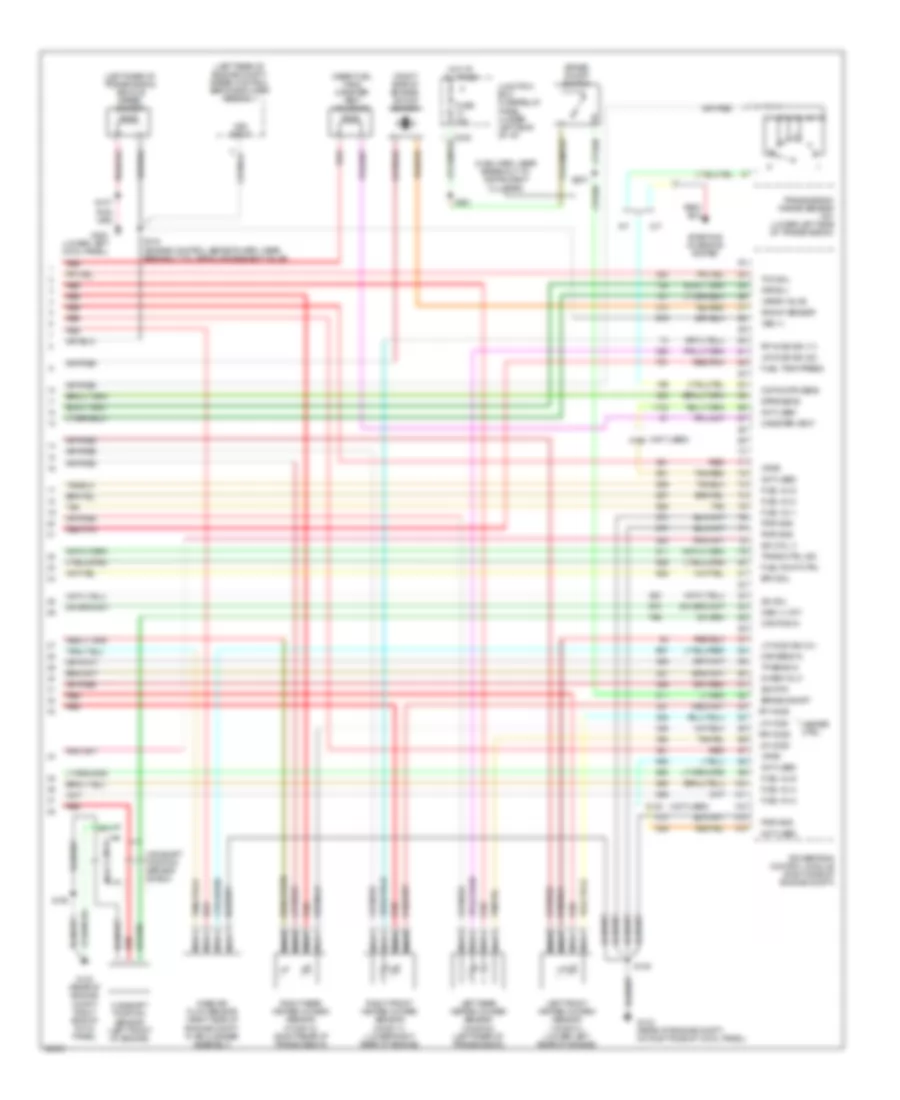
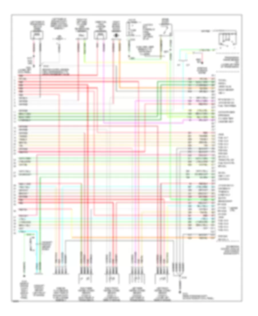
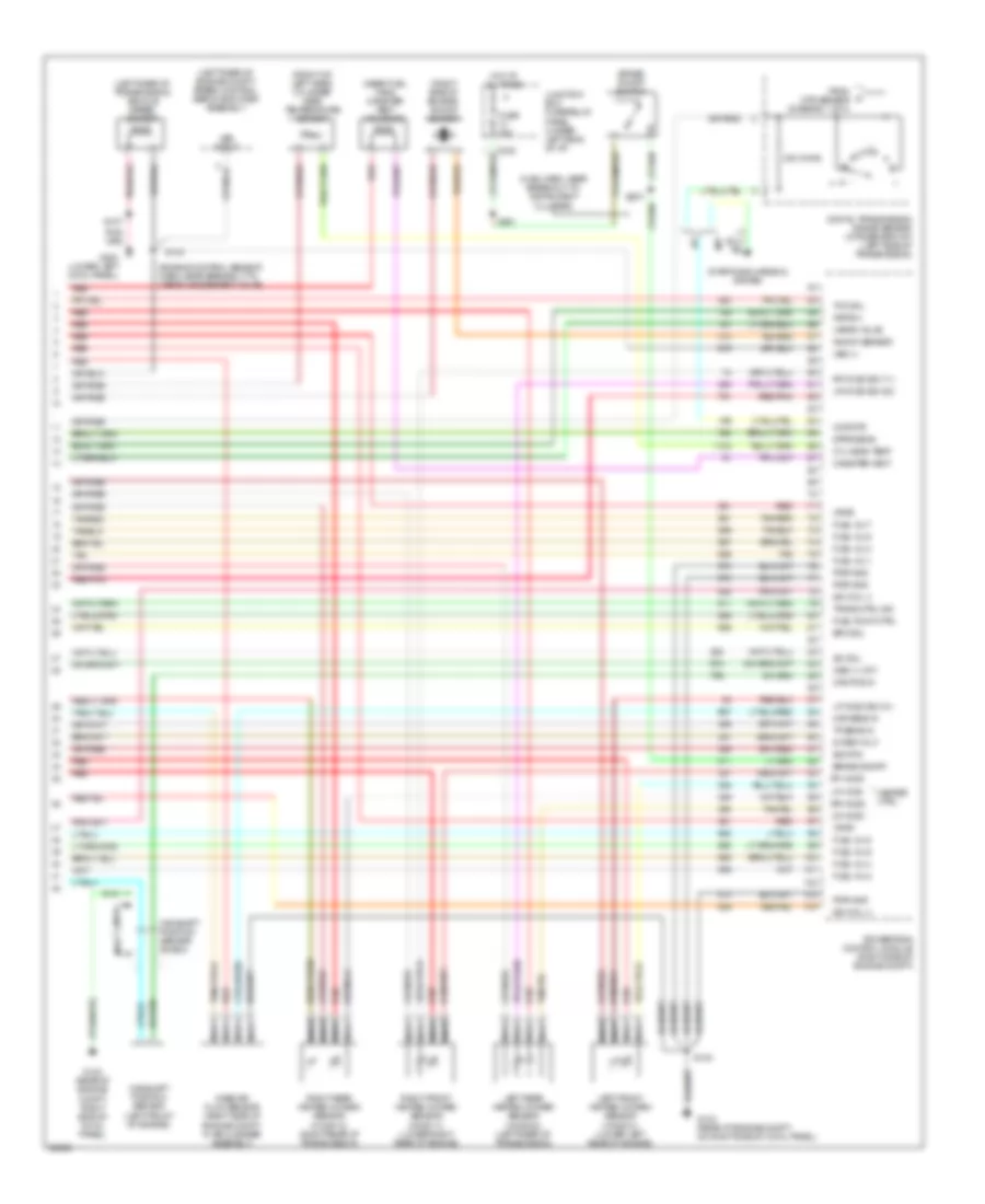
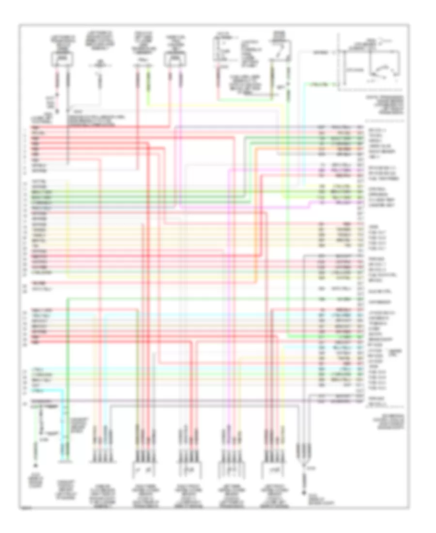
4.2L, Engine Performance Wiring Diagrams, Early Production (4 of 4) for Ford Pickup F250 1997
List of elements for 4.2L, Engine Performance Wiring Diagrams, Early Production (4 of 4) for Ford Pickup F250 1997:
- (left rear of engine compt) speed control servo/amplifier assembly
- (left rear of transmission) vehicle speed sensor
- (main harn, near breakout to instrument cluster)
- (near fuel tank) canister vent solenoid
- (not used)
- (right side of engine) knock sensor
- 5v ref volt
- A/t
- Brake on/off
- Brake on/off switch
- C120
- C242
- Cam pos in
- Camshaft position sensor (left front of engine)
- Camshaft position sensor shield
- Canister vent
- Ccp sw/tr sens
- Dpfe sens
- Epc sol
- Fuel inj 1
- Fuel inj 2
- Fuel inj 3
- Fuel inj 4
- Fuel inj 5
- Fuel inj 6
- Fuel pump ctrl
- Fuel tank press
- Fuse 15a
- G123 (rear of engine compt, on right side of cowl panel)
- G123 (rear of engine compt, right side of cowl panel)
- G200 (lower left cowl panel)
- Heater ctrl
- Hot at all times
- Iac sol
- Ign coil 3
- Junction box fuse/relay panel (under left side of i/p)
- Kap b(+)
- Knock sensor
- Left front heated oxygen sensor (ho2s 21) (lower left rear of engine)
- Left rear heated oxygen sensor (ho2s 22) (left rear of transmission)
- Lf ho2s
- Lf ho2s sig (21)
- Lr ho2s
- Lr ho2s sig (22)
- M/t
- Maf sens in
- Mass air flow sensor (right side of engine compt, in air cleaner assembly)
- Nca
- Not used
- Oss (+) (a/t)
- Powertrain control module (right side of engine compt)
- Pwr gnd
- Red
- Red/pnk
- Rf ho2s
- Rf ho2s sig (11)
- Right front heated oxygen sensor (ho2s 11) (lower right rear of engine)
- Right rear heated oxygen sensor (ho2s 12) (right rear of transmission)
- Rr ho2s
- S100
- S101
- S107
- S143 (engine control sensor harn, near breakout to vapor management valve)
- S221
- S231
- Sig rtn
- Starting/ charging system
- Tan
- Tan/red
- Tcc sol
- Tp sens in
- Trans ctrl ind
- Transmission range sensor (a/t) (lower left side of transmission)
- Vapor valve
- Vpwr
- Vss (+)
- Vss input
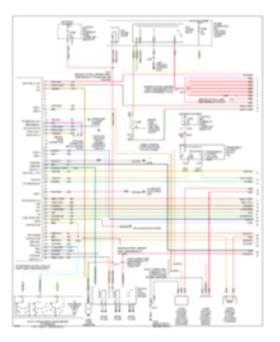
4.2L, Engine Performance Wiring Diagrams, Late Production (1 of 4) for Ford Pickup F250 1997
List of elements for 4.2L, Engine Performance Wiring Diagrams, Late Production (1 of 4) for Ford Pickup F250 1997:
- (engine control harn, near breakout to pcm)
- (engine control sensor
- (engine control sensor harn, near breakout to vapor management valve)
- (fuel charge harn, in breakout to intake runner control monitor)
- (fuel charge harn, near breakout to radio noise capacitor)
- (left radiator support) g108
- (lower left cowl panel) g201
- (partial: 16-pin connector)
- (rear of engine compt, right side of cowl panel)
- 4x4 hi/low indicator switch & generic electronic module
- 4x4 low ind sw
- 820 ohms
- Accs
- Air conditioning system
- C243
- Case gnd
- Ckp(+)
- Ckp(-)
- Data link (+)
- Data link (-)
- Data link connector (below center of i/p)
- Digital transmission range sensor (dtr sensor) (left side of transmission)
- Ect
- Ect gauge
- Engine fuse module (left side of engine compt)
- Evr ctrl
- Feps (eprom)
- Fp sending unit
- Fuel pump mon
- Fuse 30a
- Fuse 5a
- G105 (rear of right fender apron)
- G123
- Harn, near breakout to g123)
- Hot at all times
- Hot in run or start
- Iat
- Ign coil 1
- Ign coil 2
- Ignition coil (top of engine)
- Imrc 1
- Imrc 2
- Instrument cluster system
- Intake manifold runner control (top front of engine)
- Intake manifold runner control monitor 1 (rear of engine)
- Intake manifold runner control monitor 2 (right side of engine)
- Junction box fuse/relay panel (under left side of i/p)
- Maf
- Mil
- Nca
- O/d off
- Octane adjust
- Pcm power diode
- Pcm power relay
- Power distribution box (left side of engine compt)
- Powertrain control module (right side of engine compt)
- Pwr gnd
- R n
- Radio noise capacitor
- Red
- Red/ s225
- Rr ho2s sig (12)
- S100
- S103
- S106
- S107
- S116 (engine control sensor harn, near breakout to engine fuse module)
- S117
- S127
- S128
- S130
- S132
- S133
- Shift sol 1 (a/t)
- Shift sol 2 (a/t)
- Spark plugs
- Tach out
- Tcs (a/t)
- Tft
- To dtr sensor (diagram 4 of 4)
- Tr1
- Tr2a
- Tr4a
- Transmission control indicator lamp
- Transmission control switch (a/t)
- Tuning valve
- Vss (-)
4.2L, Engine Performance Wiring Diagrams, Late Production (2 of 4) for Ford Pickup F250 1997
List of elements for 4.2L, Engine Performance Wiring Diagrams, Late Production (2 of 4) for Ford Pickup F250 1997:
- (engine control sensor harn, near breakout to 35-pin conn in left rear of engine compt) s139
- (engine control sensor harn, near breakout to 38-pin conn in right rear of engine compt)
- (not used)
- (speedometer/ odometer) vehicle speed input
- (under left side of i/p) junction box fuse/relay panel
- C120
- C236
- C237
- C243
- C267
- Crankshaft position sensor (lower front of engine)
- Crankshaft position sensor shield
- Differential pressure feedback egr sensor (right side of engine)
- Electronic suspension system
- Engine coolant temperature gauge
- Engine coolant temperature sensor (front of engine)
- Fuel pump relay
- Fuel reset switch indicator
- Fuel tank pressure sensor (at fuel tank)
- Fuse 20a
- G123 (rear of engine compt, right side of cowl panel)
- Generic electronic module/ central timer module
- Hot at all times
- Instrument cluster
- Intake air temperature sensor (on intake manifold)
- Malfunction indicator
- Nca
- Octane adjust shorting bar (right rear corner of engine compt)
- Power distribution box (left side of engine compt)
- Red
- Red/pnk
- S101 (engine control harn, in breakout to pcm)
- S123 (engine control harn, near breakout to starter motor relay)
- S135 (fuel charge harn, near breakout to radio noise capacitor)
- S136 (fuel charge harn, near breakout to fuel injector 3)
- S137 (fuel charge harn, near breakout to starter motor relay)
- S138
- Tachometer
- Throttle position sensor (attached to throttle body)
- Vss input
4.2L, Engine Performance Wiring Diagrams, Late Production (3 of 4) for Ford Pickup F250 1997
List of elements for 4.2L, Engine Performance Wiring Diagrams, Late Production (3 of 4) for Ford Pickup F250 1997:
- (backup lamp sw to rear lamp feed harn, at breakout to 38-pin conn in right rear of engine compt)
- (fuel charge harn, near breakout to 42-pin conn (c120) in right rear of engine compt)
- (fuel tank) fuel pump module
- (left rear corner of engine compt)
- (right side of i/p) inertia fuel shut-off switch
- 4r70w transmission
- Egr vacuum regulator solenoid (left side of engine)
- Electronic pressure control solenoid
- Fuel injectors
- G108 (left front radiator support)
- Idle air control valve (on throttle body)
- Instrument cluster system
- Nca
- Output shaft speed sensor (left side of transmission)
- Red
- Red/pnk
- S129
- S131 (fuel charge harn, near breakout to radio noise capacitor)
- S140
- S141 (backup lamp sw to rear lamp feed harn, in breakout to 38-pin conn in right rear engine compt)
- S400
- Shift solenoids
- Tan
- Torque converter clutch solenoid
- Transmission fluid temperature sensor
- Vapor management valve
4.2L, Engine Performance Wiring Diagrams, Late Production (4 of 4) for Ford Pickup F250 1997
List of elements for 4.2L, Engine Performance Wiring Diagrams, Late Production (4 of 4) for Ford Pickup F250 1997:
- (left rear of engine compt) speed control servo/amplifier assembly
- (left rear of transmission) vehicle speed sensor
- (main harn, near breakout to instrument cluster)
- (near fuel tank) canister vent solenoid
- (not used)
- (right side of engine) knock sensor
- 240 ohms
- 5v ref volt
- A/t
- Brake on/off
- Brake on/off switch
- C120
- C242
- Cam pos in
- Camshaft position sensor (left front of engine)
- Camshaft position sensor shield
- Canister vent
- Ccp/dtr
- Digital transmission range sensor (dtr sensor-a/t) (left side of transmission)
- Dpfe sens
- Epc sol
- From dtr sensor (diagram 1 of 4)
- Fuel inj 1
- Fuel inj 2
- Fuel inj 3
- Fuel inj 4
- Fuel inj 5
- Fuel inj 6
- Fuel pump ctrl
- Fuel tank press
- Fuse 15a
- G123 (rear of engine compt, on right side of cowl panel)
- G123 (rear of engine compt, right side of cowl panel)
- G200 (lower left cowl panel)
- Heater ctrl
- Hot at all times
- Iac sol
- Ign coil 3
- Junction box fuse/relay panel (under left side of i/p)
- Kap b(+)
- Knock sensor
- Left front heated oxygen sensor (ho2s 21) (lower left rear of engine)
- Left rear heated oxygen sensor (ho2s 22) (left rear of transmission)
- Lf ho2s
- Lf ho2s sig (21)
- Lr ho2s
- Lr ho2s sig (22)
- M/t
- Maf sens in
- Mass air flow sensor (right side of engine compt, in air cleaner assembly)
- Nca
- Not used
- Oss (+) (a/t)
- Powertrain control module (right side of engine compt)
- Pwr gnd
- Red
- Red/pnk
- Rf ho2s
- Rf ho2s sig (11)
- Right front heated oxygen sensor (ho2s 11) (lower right rear of engine)
- Right rear heated oxygen sensor (ho2s 12) (right rear of transmission)
- Rr ho2s
- S100
- S101
- S107
- S143 (engine control sensor harn, near breakout to vapor management valve)
- S221
- S231
- Sig rtn
- Starting/charging system
- Tan
- Tan/red
- Tcc sol
- Tp sens in
- Trans ctrl ind
- Vapor valve
- Vpwr
- Vss (+)
- Vss input
4.6L
4.6L, Engine Performance Wiring Diagrams, Early Production (1 of 4) for Ford Pickup F250 1997
List of elements for 4.6L, Engine Performance Wiring Diagrams, Early Production (1 of 4) for Ford Pickup F250 1997:
- (engine control harn, near breakout to pcm)
- (engine control sensor harn, near breakout to g123)
- (engine control sensor harn, near breakout to g123) s134
- (engine control sensor harn, near breakout to vapor management valve)
- (fuel charge harn, near breakout of 42-pin conn in right rear of engine compt) s117
- (fuel charge harn, near breakout to radio noise cap 1) s118
- (fuel charge harn, near breakout to radio noise cap 2) s119
- (left radiator support) g108
- (lower left cowl panel) g201
- (not used)
- (partial 16-pin connector)
- (partial: 42-pin connector)
- (rear of engine compt, right side of cowl panel)
- 4x4 hi/low indicator switch & generic electronic module
- 4x4 low ind sw
- 820 ohms
- Accs
- Air conditioning system
- C120
- C243
- Case gnd
- Ckp(+)
- Ckp(-)
- Data link (+)
- Data link (-)
- Data link connector (below center of i/p)
- Ect
- Ect gauge
- Engine fuse module (left side of engine compt)
- Evr ctrl
- Feps (eprom)
- Fuel pump mon
- Fuse 30a
- Fuse 5a
- G123
- Hot at all times
- Hot in run or start
- Iat
- Ign coil 1
- Ign coil 2
- Ignition coils 1 & 2
- Ignition coils 3 & 4
- Intake manifold tuning valve (top front of engine)
- Junction box fuse/relay panel (under left side of i/p)
- Maf
- Mil
- Nca
- Not used
- O/d off
- Octane adjust
- Pcm power diode
- Pcm power relay
- Power distribution box (left side of engine compt)
- Powertrain control module (right side of engine compt)
- Pwr gnd
- Radio noise capacitor 1
- Radio noise capacitor 2
- Red
- Red/ s225
- Rr ho2s sig (12)
- S100
- S106
- S107
- S116 (engine control sensor harn, near breakout to engine fuse module)
- S127
- S128
- S130
- Shift sol 1 (a/t)
- Shift sol 2 (a/t)
- Spark plugs
- Tach out
- Tcs (a/t)
- Tft
- Transmission control indicator lamp
- Transmission control switch (a/t)
- Tuning valve
- Vss (-)
4.6L, Engine Performance Wiring Diagrams, Early Production (2 of 4) for Ford Pickup F250 1997
List of elements for 4.6L, Engine Performance Wiring Diagrams, Early Production (2 of 4) for Ford Pickup F250 1997:
- (engine control sensor harn, near breakout to 35-pin conn in left rear of engine compt) s139
- (engine control sensor harn, near breakout to 38-pin conn in right rear of engine compt)
- (lower left inner cowl panel)
- (speedometer/ odometer) vehicle speed input
- (under left side of i/p) junction box fuse/relay panel
- C236
- C237
- C243
- C267
- Crankshaft position sensor (lower front of engine)
- Crankshaft position sensor shield
- Differential pressure feedback egr sensor (right side of engine)
- Electronic suspension system
- Engine coolant temperature gauge
- Engine coolant temperature sender (left front corner of engine)
- Engine coolant temperature sensor (front of engine)
- Fuel pump relay
- Fuel reset switch indicator
- Fuel tank pressure sensor (at fuel tank)
- Fuse 20a
- G123 (rear of engine compt, right side of cowl panel)
- G200
- Generic electronic module/ central timer module
- Hot at all times
- Instrument cluster
- Intake air temperature sensor (on intake manifold)
- Malfunction indicator
- Nca
- Octane adjust shorting bar (right rear corner of engine compt)
- Power distribution box (left side of engine compt)
- Red
- Red/pnk
- S101 (engine control harn, in breakout to pcm)
- S123 (engine control harn, near breakout to starter motor relay)
- S135 (fuel charge harn, near breakout to radio noise capacitor)
- S136 (fuel charge harn, near breakout to fuel injector 3)
- S137 (fuel charge harn, near breakout to starter motor relay)
- S138
- S207
- Tachometer
- Throttle position sensor (attached to throttle body)
- Vss input
4.6L, Engine Performance Wiring Diagrams, Early Production (3 of 4) for Ford Pickup F250 1997
List of elements for 4.6L, Engine Performance Wiring Diagrams, Early Production (3 of 4) for Ford Pickup F250 1997:
- (backup lamp sw to rear lamp feed harn, at breakout to 38-pin conn in right rear of engine compt)
- (fuel charge harn, near breakout to 42-pin conn in right rear of engine compt)
- (fuel tank) fuel pump module
- (left rear corner of engine compt)
- (right side of i/p) inertia fuel shut-off switch
- 4r70w transmission
- Egr vacuum regulator solenoid (left side of engine)
- Electronic pressure control solenoid
- Fuel injectors
- G108 (left front radiator support)
- Idle air control valve (on throttle body)
- Instrument cluster system
- Nca
- Output shaft speed sensor (left side of transmission)
- Red
- Red/pnk
- S129
- S131 (fuel charge harn, near breakout to radio noise capacitor)
- S140
- S141 (backup lamp sw to rear lamp feed harn, in breakout to 38-pin conn in right rear engine compt)
- S400
- Shift solenoids
- Tan
- Tan/ red
- Tan/red
- Torque converter clutch solenoid
- Transmission fluid temperature sensor
- Vapor management valve
4.6L, Engine Performance Wiring Diagrams, Early Production (4 of 4) for Ford Pickup F250 1997
List of elements for 4.6L, Engine Performance Wiring Diagrams, Early Production (4 of 4) for Ford Pickup F250 1997:
- (engine control sensor harn, near breakout to vapor management valve)
- (front of left head) cylinder head temperature sensor
- (left rear of engine compt) speed control servo/amplifier assembly
- (left rear of transmission) vehicle speed sensor
- (main harn, near breakout to instrument cluster)
- (near fuel tank) canister vent solenoid
- (right side of engine) knock sensor
- 5v ref volt
- A/t
- Brake on/off
- Brake on/off switch
- C242
- Cam pos in
- Camshaft position sensor (left front of engine)
- Camshaft position sensor shield
- Canister vent
- Ccp sw/tr sens
- Cyl head temp
- Dpfe sens
- Epc sol
- Fuel inj 1
- Fuel inj 2
- Fuel inj 3
- Fuel inj 4
- Fuel inj 5
- Fuel inj 6
- Fuel inj 7
- Fuel inj 8
- Fuel pump ctrl
- Fuel tank press
- Fuse 15a
- G123 (rear of engine compt, on right side of cowl panel)
- G123 (rear of engine compt, right side of cowl panel)
- G200 (lower left cowl panel)
- Heater ctrl
- Hot at all times
- Iac sol
- Ign coil 3
- Ign coil 4
- Junction box fuse/relay panel (under left side of i/p)
- Kap b(+)
- Knock sensor
- Left front heated oxygen sensor (ho2s 21) (lower left rear of engine)
- Left rear heated oxygen sensor (ho2s 22) (left rear of transmission)
- Lf ho2s
- Lf ho2s sig (21)
- Lr ho2s
- Lr ho2s sig (22)
- M/t
- Maf sens in
- Mass air flow sensor (right side of engine compt, in air cleaner assembly)
- Nca
- Oss (+) (a/t)
- Powertrain control module (right side of engine compt)
- Pwr gnd
- Red
- Red/pnk
- Rf ho2s
- Rf ho2s sig (11)
- Right front heated oxygen sensor (ho2s 11) (lower right rear of engine)
- Right rear heated oxygen sensor (ho2s 12) (right rear of transmission)
- Rr ho2s
- S100
- S101
- S107
- S143
- S221
- S231
- Sig rtn
- Starting/ charging system
- Tan
- Tan/red
- Tcc sol
- Tp sens in
- Trans ctrl ind
- Transmission range sensor (a/t) (lower left side of transmission)
- Vapor valve
- Vpwr
- Vss (+)
- Vss input
4.6L, Engine Performance Wiring Diagrams, Late Production (1 of 4) for Ford Pickup F250 1997
List of elements for 4.6L, Engine Performance Wiring Diagrams, Late Production (1 of 4) for Ford Pickup F250 1997:
- (engine control harn, near breakout to pcm)
- (engine control sensor harn, near breakout to g123)
- (engine control sensor harn, near breakout to vapor management valve)
- (fuel charge harn, near breakout of 42-pin conn in right rear of engine compt) s117
- (fuel charge harn, near breakout to radio noise cap 1) s118
- (fuel charge harn, near breakout to radio noise cap 2) s119
- (left radiator support) g108
- (lower left cowl panel) g201
- (not used)
- (partial: 16-pin connector)
- (partial: 42-pin connector)
- (rear of engine compt, right side of cowl panel) g123
- 4x4 hi/low indicator switch & generic electronic module
- 4x4 low ind sw
- 820 ohms
- Accs
- Air conditioning system
- C120
- C243
- Case gnd
- Ckp(+)
- Ckp(-)
- Data link (+)
- Data link (-)
- Data link connector (below center of i/p)
- Digital transmission range sensor (dtr sensor) (left side of transmission)
- Ect
- Ect gauge
- Engine fuse module (left side of engine compt)
- Evr ctrl
- Feps (eprom)
- Fp sending unit
- Fuel pump mon
- Fuse 30a
- Fuse 5a
- Hot at all times
- Hot in run or start
- Iat
- Ign coil 1
- Ign coil 2
- Ignition coils 1 & 2
- Ignition coils 3 & 4
- Instrument cluster system
- Intake manifold tuning valve (top front of engine)
- Junction box fuse/relay panel (under left side of i/p)
- Maf
- Mil
- Nca
- Not used
- O/d off
- Octane adjust
- Pcm power diode
- Pcm power relay
- Power distribution box (left side of engine compt)
- Powertrain control module (right side of engine compt)
- Pwr gnd
- R n
- Radio noise capacitor 1
- Radio noise capacitor 2
- Red
- Red/ s225
- Rr ho2s sig (12)
- S100
- S106
- S107
- S116 (engine control sensor harn, near breakout to engine fuse module)
- S127
- S128
- S130
- Shift sol 1 (a/t)
- Shift sol 2 (a/t)
- Spark plugs
- Tach out
- Tcs (a/t)
- Tft
- To dtr sensor (diagram 4 of 4)
- Tr1
- Tr2a
- Tr4a
- Transmission control indicator lamp
- Transmission control switch (a/t)
- Tuning valve
- Vss (-)
4.6L, Engine Performance Wiring Diagrams, Late Production (2 of 4) for Ford Pickup F250 1997
List of elements for 4.6L, Engine Performance Wiring Diagrams, Late Production (2 of 4) for Ford Pickup F250 1997:
- (engine control sensor harn, near breakout to 35-pin conn in left rear of engine compt) s139
- (engine control sensor harn, near breakout to 38-pin conn in right rear of engine compt)
- (lower left inner cowl panel)
- (speedometer/ odometer) vehicle speed input
- (under left side of i/p) junction box fuse/relay panel
- C236
- C237
- C243
- C267
- Crankshaft position sensor (lower front of engine)
- Crankshaft position sensor shield
- Differential pressure feedback egr sensor (right side of engine)
- Electronic suspension system
- Engine coolant temperature gauge
- Engine coolant temperature sender (left front corner of engine)
- Engine coolant temperature sensor (front of engine)
- Fuel pump relay
- Fuel reset switch indicator
- Fuel tank pressure sensor (at fuel tank)
- Fuse 20a
- G123 (rear of engine compt, right side of cowl panel)
- G200
- Generic electronic module/ central timer module
- Hot at all times
- Instrument cluster
- Intake air temperature sensor (on intake manifold)
- Malfunction indicator
- Nca
- Octane adjust shorting bar (right rear corner of engine compt)
- Power distribution box (left side of engine compt)
- Red
- Red/pnk
- S101 (engine control harn, in breakout to pcm)
- S123 (engine control harn, near breakout to starter motor relay)
- S135 (fuel charge harn, near breakout to radio noise capacitor)
- S136 (fuel charge harn, near breakout to fuel injector 3)
- S137 (fuel charge harn, near breakout to starter motor relay)
- S138
- S207
- Tachometer
- Throttle position sensor (attached to throttle body)
- Vss input
4.6L, Engine Performance Wiring Diagrams, Late Production (3 of 4) for Ford Pickup F250 1997
List of elements for 4.6L, Engine Performance Wiring Diagrams, Late Production (3 of 4) for Ford Pickup F250 1997:
- (backup lamp sw to rear lamp feed harn, at breakout to 38-pin conn in right rear of engine compt)
- (fuel charge harn, near breakout to 42-pin conn in right rear of engine compt)
- (fuel tank) fuel pump module
- (left rear corner of engine compt)
- (right side of i/p) inertia fuel shut-off switch
- 4r70w transmission
- Egr vacuum regulator solenoid (left side of engine)
- Electronic pressure control solenoid
- Fuel injectors
- G108 (left front radiator support)
- Idle air control valve (on throttle body)
- Instrument cluster system
- Nca
- Output shaft speed sensor (left side of transmission)
- Red
- Red/pnk
- S129
- S131 (fuel charge harn, near breakout to radio noise capacitor)
- S140
- S141 (backup lamp sw to rear lamp feed harn, in breakout to 38-pin conn in right rear engine compt)
- S400
- Shift solenoids
- Tan
- Tan/ red
- Tan/red
- Torque converter clutch solenoid
- Transmission fluid temperature sensor
- Vapor management valve
4.6L, Engine Performance Wiring Diagrams, Late Production (4 of 4) for Ford Pickup F250 1997
List of elements for 4.6L, Engine Performance Wiring Diagrams, Late Production (4 of 4) for Ford Pickup F250 1997:
- (engine control sensor harn, near breakout to vapor management valve)
- (front of left head) cylinder head temperature sensor
- (left rear of engine compt) speed control servo/amplifier assembly
- (left rear of transmission) vehicle speed sensor
- (main harn, near breakout to instrument cluster)
- (near fuel tank) canister vent solenoid
- (right side of engine) knock sensor
- 240 ohms
- 5v ref volt
- A/t
- Brake on/off
- Brake on/off switch
- C242
- Cam pos in
- Camshaft position sensor (left front of engine)
- Camshaft position sensor shield
- Canister vent
- Ccp/dtr
- Cyl head temp
- Digital transmission range sensor (dtr sensor-a/t) (left side of transmission)
- Dpfe sens
- Epc sol
- From dtr sensor (diagram 1 of 4)
- Fuel inj 1
- Fuel inj 2
- Fuel inj 3
- Fuel inj 4
- Fuel inj 5
- Fuel inj 6
- Fuel inj 7
- Fuel inj 8
- Fuel pump ctrl
- Fuse 15a
- G123 (rear of engine compt, on right side of cowl panel)
- G123 (rear of engine compt, right side of cowl panel)
- G200 (lower left cowl panel)
- Heater ctrl
- Hot at all times
- Iac sol
- Ign coil 3
- Ign coil 4
- Junction box fuse/relay panel (under left side of i/p)
- Kap b(+)
- Knock sensor
- Left front heated oxygen sensor (ho2s 21) (lower left rear of engine)
- Left rear heated oxygen sensor (ho2s 22) (left rear of transmission)
- Lf ho2s
- Lf ho2s sig (21)
- Lr ho2s
- Lr ho2s sig (22)
- M/t
- Maf sens in
- Mass air flow sensor (right side of engine compt, in air cleaner assembly)
- Nca
- Oss (+) (a/t)
- Powertrain control module (right side of engine compt)
- Pwr gnd
- Red
- Red/pnk
- Rf ho2s
- Rf ho2s sig (11)
- Right front heated oxygen sensor (ho2s 11) (lower right rear of engine)
- Right rear heated oxygen sensor (ho2s 12) (right rear of transmission)
- Rr ho2s
- S100
- S101
- S107
- S143
- S221
- S231
- Sig rtn
- Starting/charging system
- Tan
- Tan/red
- Tcc sol
- Tp sens in
- Trans ctrl ind
- Vapor valve
- Vpwr
- Vss (+)
- Vss input
5.4L
5.4L, Engine Performance Wiring Diagrams (1 of 4) for Ford Pickup F250 1997
List of elements for 5.4L, Engine Performance Wiring Diagrams (1 of 4) for Ford Pickup F250 1997:
- (engine control harn, near breakout to pcm)
- (engine control sensor harn, near breakout to vapor management valve)
- (expedition)
- (fuel charge harn, in breakout to fuel injector 3)
- (fuel charge harn, in breakout to fuel injector 7)
- (fuel charge harn, near breakout to 42-pin inline conn in right rear of engine compt)
- (left radiator support) g108
- (lower left cowl panel) g201
- (overhead console)
- (rear of engine compt)
- 4x4 low ind sw
- A/c on sig
- Air conditioning system
- Air suspn vss
- Body computer system
- C243
- Case gnd
- Ckp (+)
- Ckp (-)
- Data link (+)
- Data link (-)
- Data link connector (partial) (center of dash)
- Digital transmission range sensor (dtr sensor) (left side of transmission)
- Dtr-tr1
- Dtr-tr2
- Dtr-tr4
- E4od ccs
- E4od ss1
- E4od ss2
- Ect
- Electronic suspension system
- Engine fuse module (left side of engine compt)
- Evr sol
- Feps (eprom)
- Fp sending unit
- Fuel pump mon
- Fuse 30a
- Fuse 5a
- G123
- Hot at all times
- Hot in run or start
- Iat
- Ign coil 1
- Ign coil 3
- Ign coil 5
- Ign coil 6
- Ignition coils
- Instrument cluster system
- Intake tune vlv
- Junction box fuse/relay panel (under left side of dash)
- Maf
- Mil
- Nca
- O/d off
- Octane adjust
- Od off ind
- Ohms
- Otc module
- Pcm power diode
- Pcm power relay
- Power distribution box (left side of engine compt)
- Powertrain control module (right side of engine compt)
- Pwr gnd
- R n
- Radio noise capacitor
- Red
- Rr ho2s (12)
- S100
- S106
- S107
- S116
- S117
- S127
- S128
- S161
- S162
- S225
- Tach
- Tcs
- Tft
- To dtr sensor (diagram 4 of 4)
- Transmission control indicator lamp
- Transmission control switch
- Vss (-)
5.4L, Engine Performance Wiring Diagrams (2 of 4) for Ford Pickup F250 1997
List of elements for 5.4L, Engine Performance Wiring Diagrams (2 of 4) for Ford Pickup F250 1997:
- (engine control sensor harn, near breakout to 35-pin conn in left rear of engine compt) s139
- (engine control sensor harn, near breakout to 38-pin conn in right rear of engine compt)
- (lower left kick panel)
- (speedometer/ odometer) vehicle speed input
- (under left side of dash) junction box fuse/relay panel
- C236
- C237
- C243
- C267
- Crankshaft position sensor (lower front of engine)
- Crankshaft position sensor shield
- Differential pressure feedback egr sensor (left side of engine)
- Electronic suspension system
- Engine coolant temperature gauge
- Engine coolant temperature sender (left front corner of engine)
- Fuel pump relay
- Fuel reset switch indicator
- Fuel tank pressure sensor (at fuel tank)
- Fuse 20a
- G123 (rear of engine compt)
- G200
- Generic electronic module/ central timer module
- Hot at all times
- Instrument cluster
- Intake air temperature sensor (on intake manifold)
- Knock sensor (top right rear side of engine)
- Knock sensor shield
- Malfunction indicator
- Nca
- Octane adjust shorting bar (right rear corner of engine compt)
- Power distribution box (left side of engine compt)
- Red
- Red/pnk
- S101 nca
- S123 (engine control harn, near breakout to starter motor relay)
- S135 (fuel charge harn, near breakout to radio noise capacitor)
- S136 (fuel charge harn, near breakout to fuel injector 3)
- S137 (fuel charge harn, near breakout to starter motor relay)
- S138
- S199 nca
- S207
- Tachometer
- Throttle position sensor (attached to throttle body)
- Vss input
5.4L, Engine Performance Wiring Diagrams (3 of 4) for Ford Pickup F250 1997
List of elements for 5.4L, Engine Performance Wiring Diagrams (3 of 4) for Ford Pickup F250 1997:
- (backup lamp sw to rear lamp feed harn, at breakout to 38-pin conn in right rear of engine compt)
- (backup lamp sw to rear lamp feed harn, in breakout to 38-pin conn in right rear engine compt)
- (fuel charge harn, near breakout to 42-pin conn in right rear of engine compt)
- (fuel tank) fuel pump module
- (right side of dash) inertia fuel shut-off switch
- Coast clutch solenoid
- E4od transmission
- Egr vacuum regulator solenoid (left side of engine)
- Electronic pressure control solenoid
- Fuel injectors
- G108 (left front radiator support)
- Idle air control valve (on left side of intake manifold)
- Instrument cluster system
- Intake manifold tuning valve (on left side of engine)
- Nca
- Red
- Red/pnk
- S129
- S131 (fuel charge harn, near breakout to radio noise capacitor)
- S140
- S141
- S400
- Shift solenoid
- Tan
- Tan/ red
- Tan/red
- Torque converter clutch solenoid
- Transmission fluid temperature sensor
- Vapor management valve (vmv) (left rear corner of engine compt)
5.4L, Engine Performance Wiring Diagrams (4 of 4) for Ford Pickup F250 1997
List of elements for 5.4L, Engine Performance Wiring Diagrams (4 of 4) for Ford Pickup F250 1997:
- (engine control sensor harn, near breakout to c165, windshield wiper motor)
- (front of left head) cylinder head temperature sensor
- (left rear of engine compt) speed control servo/amplifier assembly
- (left rear of transmission) vehicle speed sensor
- (main harn, near breakout to 16-pin inline conn behind left side of dash)
- (near fuel tank) canister vent solenoid
- 270 ohms
- 5v ref
- Brake on/off
- Brake on/off switch
- C242
- Camshaft position sensor (left front of engine)
- Camshaft position sensor shield
- Canister vent
- Cmp sensor
- Cyl head temp
- Digital transmission range sensor (dtr sensor-a/t) (left side of transmission)
- Dpfe sens
- Dtr-tr3a
- Epc sol
- From dtr sensor (diagram 1 of 4)
- Fuel inj 1
- Fuel inj 2
- Fuel inj 3
- Fuel inj 4
- Fuel inj 5
- Fuel inj 6
- Fuel inj 7
- Fuel inj 8
- Fuel pump ctrl
- Fuel tank press
- Fuse 15a
- G123 (rear of engine compt)
- G200 (lower left kick panel)
- Heater ctrl
- Hot at all times
- Idle air ctrl
- Ign coil 2
- Ign coil 4
- Ign coil 7
- Ign coil 8
- Junction box fuse/relay panel (under left side of dash)
- Kap b(+)
- Knock sensor
- Left front heated oxygen sensor (ho2s 21) (lower left rear of engine)
- Left rear heated oxygen sensor (ho2s 22) (left rear of transmission)
- Lf ho2s
- Lf ho2s sig (21)
- Lr ho2s
- Maf sens in
- Mass air flow sensor (right side of engine compt, in air cleaner assembly)
- Nca
- Powertrain control module (right side of engine compt)
- Pwr gnd
- Red
- Red/pnk
- Rf ho2s
- Rf ho2s sig (11)
- Rf ho2s sig (22)
- Right front heated oxygen sensor (ho2s 11) (lower right rear of engine)
- Right rear heated oxygen sensor (ho2s 12) (right rear of transmission)
- Rr ho2s
- S100
- S101
- S107
- S143
- S199
- S231
- Sig rtn
- Tan
- Tan/red
- Tcc sol
- Tp sens in
- Vapor valve
- Vpwr
- Vss (+)
- Vss input