ENGINE PERFORMANCE
2.3L
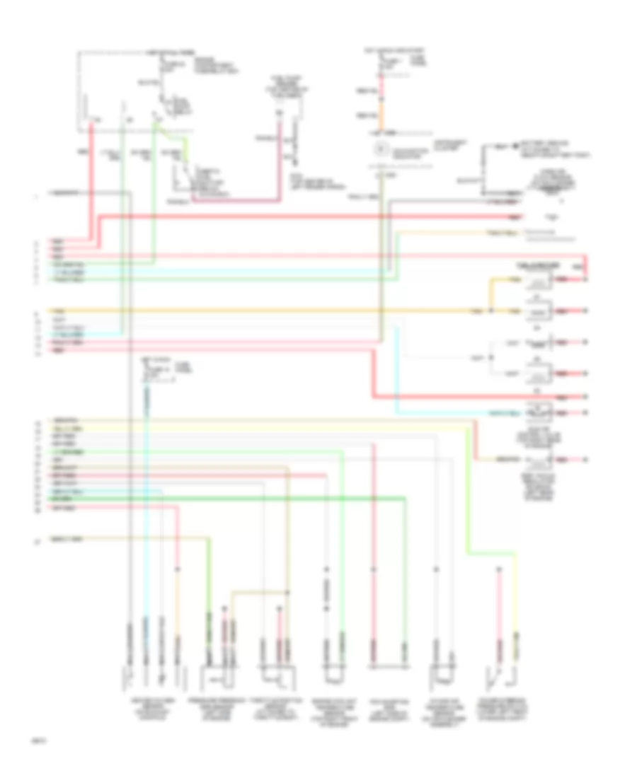
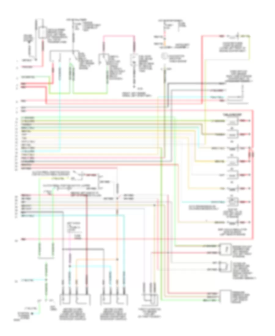
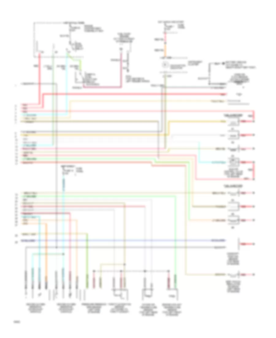
2.3L MFI, Engine Performance Wiring Diagrams (1 of 2) for Ford Ranger Splash 1994

List of elements for 2.3L MFI, Engine Performance Wiring Diagrams (1 of 2) for Ford Ranger Splash 1994:
- 3-4 shift solenoid
- A4ld automatic transmission
- Acc
- Accs
- Acd
- Air conditioning system
- Boo
- Brake on/off switch (on brake pedal support)
- C198
- C199
- Cid
- Ckp
- Ckp (cid)
- Coil 1
- Coil 2
- Coil 3
- Coil 4
- Cpp m/t-pnp a/t
- Crankshaft position sensor (right front of engine
- Cse gnd
- Data (+)
- Data (-)
- Data link connector (on rear of engine compt fuse/relay box)
- Diode
- Dpfe
- Dpi
- Ect
- Engine compartment fuse/relay box
- Evr
- Fpm
- Fuse 10 15a
- Fuse 4 30a
- Fuse panel
- G104 (left rear of engine compartment)
- G104 left rear corner of engine compt)
- Ho2s
- Ho2s gnd
- Hot at all times
- Iac
- Iat
- Idm
- Ign
- Ign gnd
- Ignition control module (left top front of engine)
- Ignition switch
- Inj bank 1
- Inj bank 2
- Kapwr
- Lock
- Maf
- Maf rtn
- Nca
- Noise capacitor (near secondary coil)
- Oct adj
- Off
- Pcm power relay
- Pip
- Pnk
- Powertrain control module (left rear corner of engine compartment)
- Primary coil (right) (top right front of engine)
- Psp
- Pwr gnd
- Red
- Run
- Secondary coil (left) (top right front of engine)
- Self test input connector (on rear of engine compt fuse/relay box)
- Sig rtn
- Spout
- Spout check connector (left side of engine compt)
- Start
- Starting/ charging system
- Sti
- Sto/mil
- Tan
- Tcc
- Torque converter clutch solenoid
- Vehicle speed sensor (left rear of transmission)
- Vpwr
- Vref
- Vss (+)
- Vss (-)
- Wac
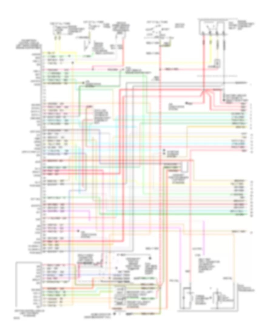
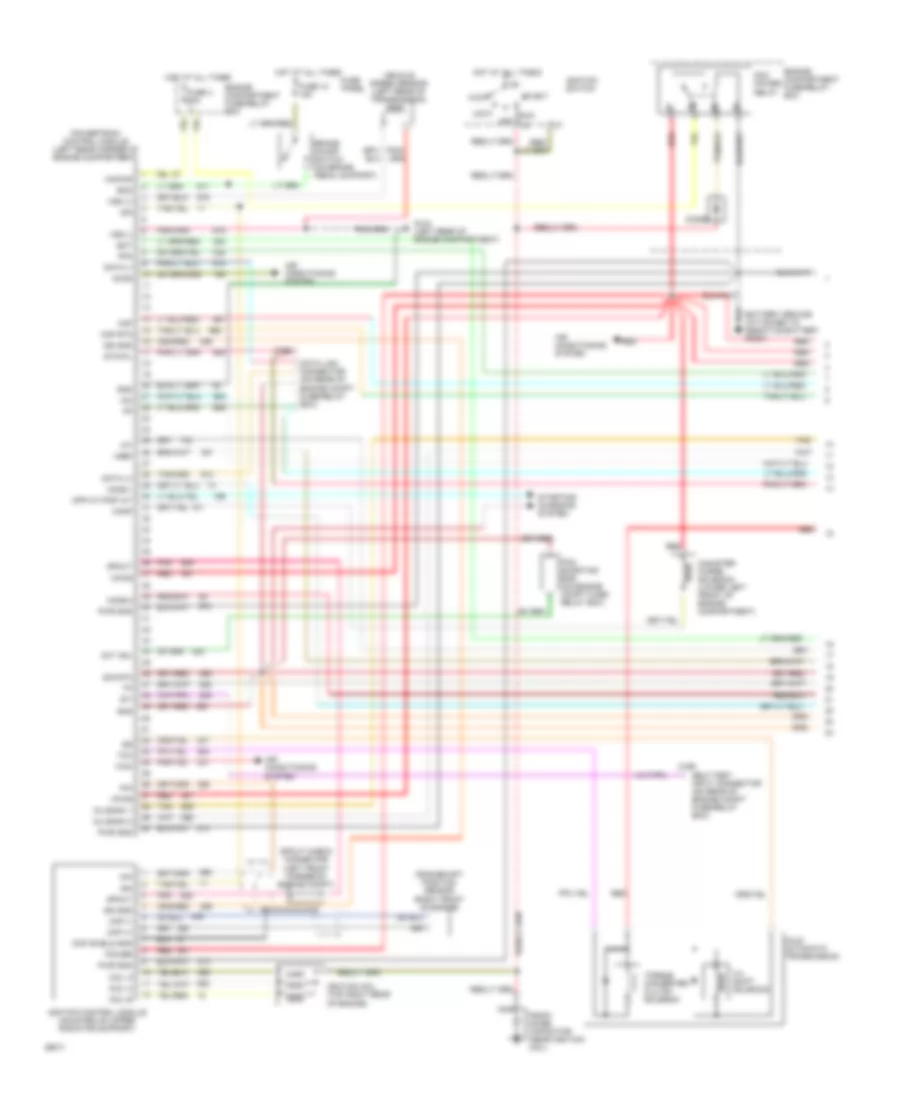
2.3L MFI, Engine Performance Wiring Diagrams (2 of 2) for Ford Ranger Splash 1994
List of elements for 2.3L MFI, Engine Performance Wiring Diagrams (2 of 2) for Ford Ranger Splash 1994:
- C251
- Egr vacuum regulator solenoid (left rear of engine)
- Engine compartment fuse/relay box
- Engine coolant temperature sensor (top right front of engine)
- Fuel injectors
- Fuel pump relay
- Fuel pump/ sender (top center of fuel tank)
- Fuse 18 15a
- Fuse 22 20a
- Fuse 7 15a
- Fuse panel
- G104 (top center of left fender apron)
- Heated oxygen sensor (on exhaust manifold)
- Hot at all times
- Hot in run
- Hot in run and start
- Idle air control valve (top right rear of engine)
- Inertia fuel shut-off (below glove box)
- Instrument cluster
- Intake air temperature sensor (on air cleaner assembly)
- Malfunction indicator
- Mass air flow sensor (on air cleaner assembly)
- Nca
- Pcm shorting bar (left side of engine compt)
- Power steering pressure switch (lower left front of engine compt)
- Pressure feedback egr sensor (left side of engine)
- Red
- Tan
- Throttle position sensor (attached to throttle body)
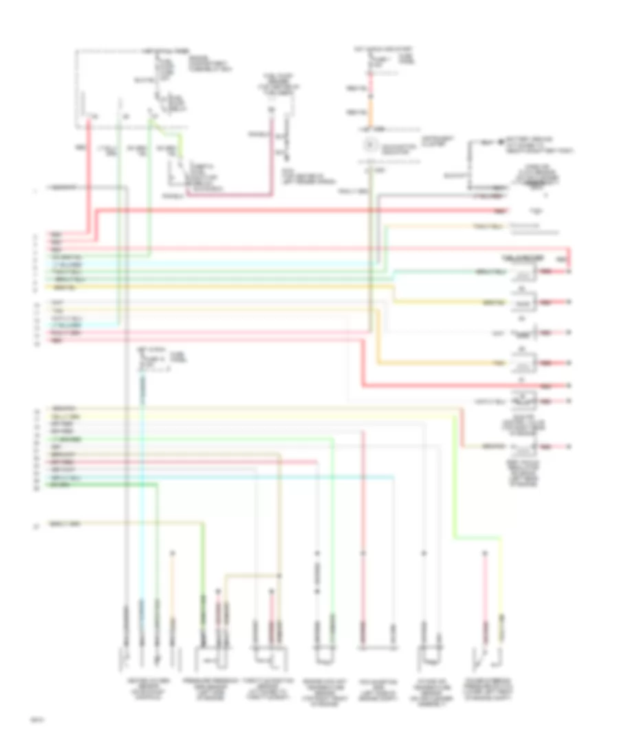
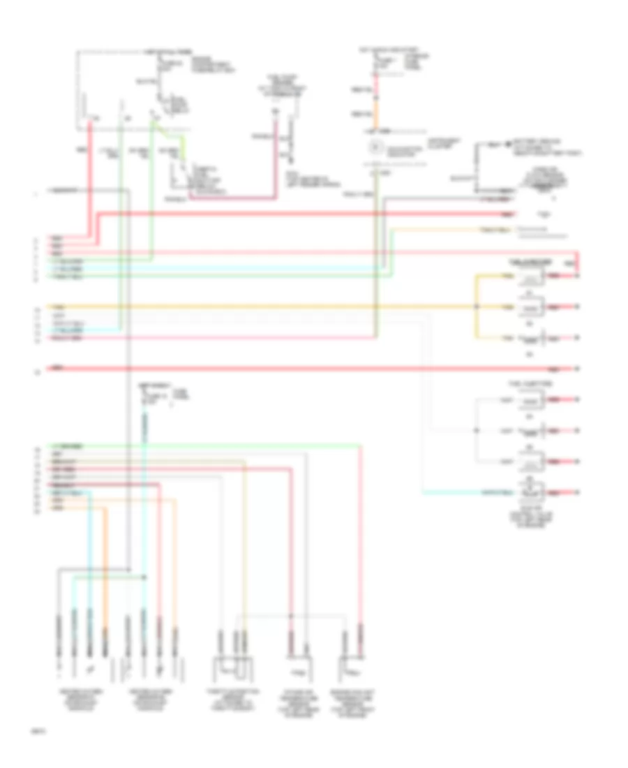
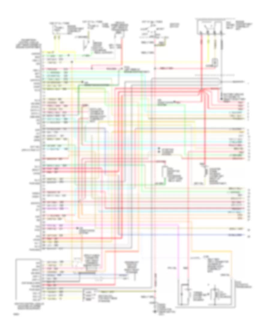
2.3L SFI, Engine Performance Wiring Diagrams (1 of 2) for Ford Ranger Splash 1994
List of elements for 2.3L SFI, Engine Performance Wiring Diagrams (1 of 2) for Ford Ranger Splash 1994:
- 3-4 shift solenoid
- A4ld automatic transmission
- Acc
- Accs
- Air conditioning system
- Boo
- Brake on/off switch (on brake pedal support)
- C198
- C199
- Camshaft position sensor (top front of engine)
- Cid
- Ckp
- Ckp (cid)
- Coil 1
- Coil 2
- Coil 3
- Coil 4
- Cpp m/t-pnp a/t
- Crankshaft position sensor (right front of engine
- Cse gnd
- Data (+)
- Data (-)
- Data link connector (on rear of engine compt fuse/relay box)
- Diode
- Dpfe
- Dpi
- Ect
- Eec pwr fuse 30a
- Engine compartment fuse/relay box
- Evr
- Fpm
- Fuse 10 15a
- Fuse panel
- G104 (left rear of engine compartment)
- G104 left rear corner of engine compt)
- Ho2s
- Hot at all times
- Iac
- Iat
- Idm
- Ign
- Ign gnd
- Ignition control module (left top front of engine)
- Ignition switch
- Inj 3
- Inj 4
- Inj bank 1
- Inj bank 2
- Kapwr
- Lock
- Maf
- Maf rtn
- Nca
- Noise capacitor (near secondary coil)
- Oct adj
- Off
- Pcm power relay
- Pip
- Pnk
- Powertrain control module (left rear corner of engine compartment)
- Primary coil (right) (top right front of engine)
- Psp
- Pwr gnd
- Red
- Run
- Secondary coil (left) (top right front of engine)
- Self test input connector (on rear of engine compt fuse/relay box)
- Sig rtn
- Spout
- Spout check connector (left side of engine compt)
- Start
- Starting/ charging system
- Sti
- Sto/mil
- Tan
- Tcc
- Torque converter clutch solenoid
- Vehicle speed sensor (left rear of transmission)
- Vpwr
- Vref
- Vss (+)
- Vss (-)
- Wac
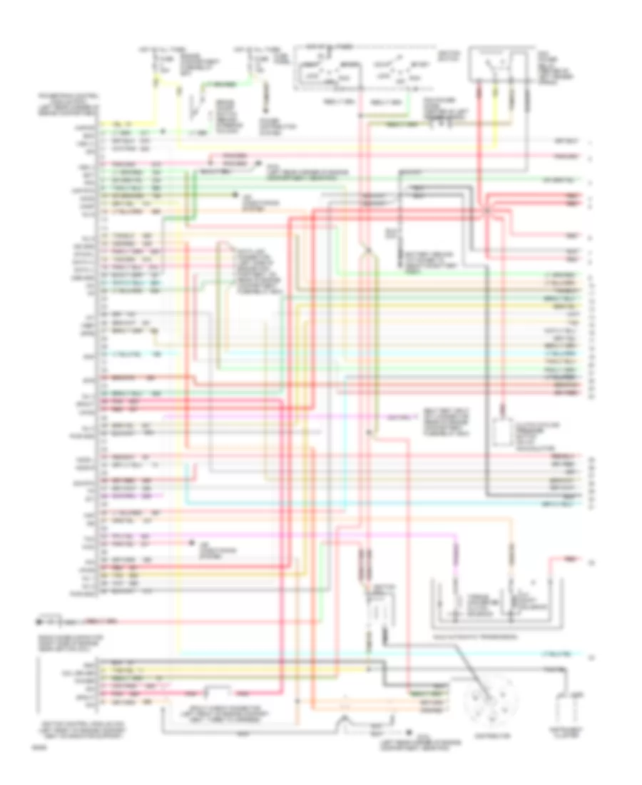
2.3L SFI, Engine Performance Wiring Diagrams (2 of 2) for Ford Ranger Splash 1994
List of elements for 2.3L SFI, Engine Performance Wiring Diagrams (2 of 2) for Ford Ranger Splash 1994:
- C251
- Egr vacuum regulator solenoid (left rear of engine)
- Engine compartment fuse/relay box
- Engine coolant temperature sensor (top right front of engine)
- Fuel injectors
- Fuel pump relay
- Fuel pump/ sender (top center of fuel tank)
- Fuse 18 15a
- Fuse 7 15a
- Fuse panel
- G104 (top center of left fender apron)
- Heated oxygen sensor (on exhaust manifold)
- Hot at all times
- Hot in run
- Hot in run and start
- Idle air control valve (top right rear of engine)
- Inertia fuel shut-off (below glove box)
- Instrument cluster
- Intake air temperature sensor (on air cleaner assembly)
- Malfunction indicator
- Mass air flow sensor (on air cleaner assembly)
- Nca
- Pcm shorting bar (left side of engine compt)
- Power steering pressure switch (lower left front of engine compt)
- Pressure feedback egr sensor (left side of engine)
- Red
- Tan
- Throttle position sensor (attached to throttle body)
3.0L
3.0L, Engine Performance Wiring Diagrams (1 of 2) for Ford Ranger Splash 1994
List of elements for 3.0L, Engine Performance Wiring Diagrams (1 of 2) for Ford Ranger Splash 1994:
- (left rear corner of engine compartment, near pcm)
- 4-3 shift solenoid
- A4ld automatic transmission
- Acc
- Accs
- Air conditioning system
- Boo
- Brake on/off switch (behind steering column)
- C250
- Canp
- Clutch cycling pressure switch (on a/c accumulator)
- Coil driver
- Cse gnd
- Data (+)
- Data (-)
- Data link connector (left side of engine com- partment, on rear of engine compartment fuse/relay box)
- Distributor
- Dpfe
- Ect
- Engine compartment fuse/relay box
- Evr
- Fpm
- Fuse 15a
- Fuse 30a
- Fuse panel
- G104
- G104 (left rear corner of engine compartment, near pcm)
- Gnd
- H2os l
- H2os r
- Hot at all times
- Iac
- Iat
- Idm
- Ign gnd
- Ignition coil
- Ignition control module (icm) (left front of engine compart- ment on radiator support)
- Ignition switch
- Inj 1
- Inj 2
- Inj 3
- Inj 4
- Inj 5
- Inj 6
- Instrument cluster
- Kapwr
- Lock
- Maf
- Maf rtn
- Nca
- Off
- Pcm power diode (center of left fender apron)
- Pcm power relay (center of left fender apron)
- Pip
- Pnk
- Pnp
- Power
- Power distribution system
- Powertrain control module (pcm) (left rear corner of engine compartment)
- Pwr gnd
- Radio noise capacitor (right side of engine, near ignition coil)
- Red
- Run
- Self test input (sti) connector (rear of engine compartment fuse/relay box)
- Sig rtn
- Spout
- Spout check connector (left front of engine compart- ment, taped to harness)
- Start
- Sti
- Sto/mil
- Tan
- Tcc
- Torque converter clutch solenoid
- Vpwr
- Vref
- Vss (+)
- Vss (-)
- Wac
3.0L, Engine Performance Wiring Diagrams (2 of 2) for Ford Ranger Splash 1994
List of elements for 3.0L, Engine Performance Wiring Diagrams (2 of 2) for Ford Ranger Splash 1994:
- (behind left side of i/p, left of steering column)
- (front left fender apron, left of battery)
- (not used)
- A/t
- Auto transmission or california emission only
- C251
- Canister purge (canp) solenoid (lower left front of engine compartment)
- Clutch pedal position switch (top of clutch pedal support)
- Clutch pedal position switch jumper
- Cruise control system
- Egr vacuum regulator (evr) solenoid (left rear of engine)
- Engine compartment fuse/relay box
- Engine coolant temperature (ect) sensor (top left front of engine)
- Fuel injectors
- Fuel pump relay (center of left fender apron, in engine)
- Fuel pump/ fuel gauge sender (below rear of vehicle, top of fuel tank)
- Fuse 18 15a
- Fuse 20a
- Fuse 7 15a
- Fuse panel
- G100
- Heated oxygen sensor (ho2s) #1 (lower right rear of engine compartment, on exhaust manifold)
- Heated oxygen sensor (ho2s) #2 (lower left rear of engine compartment, on exhaust manifold)
- Hot at all times
- Hot in run
- Hot in start or run
- Idle air control valve (top left front of engine)
- Inertia fuel shut-off switch (opens on impact) (below right side of i/p, below glove box)
- Instrument cluster
- Intake air temperature (iat) sensor (right side of engine compart- ment, on air cleaner assembly)
- M/t
- Malfunction indicator "check engine"
- Mass air flow (maf) sensor (right side of engine compartment, on air cleaner assembly)
- Nca
- Pressure feedback egr (pfe) sensor (left side of engine)
- Red
- Starting/ charging system
- Tan
- Throttle position (tp) sensor (top left on throttle body)
- Vehicle speed sensor (vss) (4x2: left rear of transmission, 4x4: top of transfer case)
4.0L
4.0L MFI, Engine Performance Wiring Diagrams (1 of 2) for Ford Ranger Splash 1994
List of elements for 4.0L MFI, Engine Performance Wiring Diagrams (1 of 2) for Ford Ranger Splash 1994:
- 3-4 shift solenoid
- A4ld automatic transmission
- Acc
- Accs
- Air conditioning system
- Boo
- Brake on/off switch (on brake pedal support)
- C198
- C199
- Canister purge solenoid (lower left front of engine compartment)
- Canp
- Ckp (+)
- Ckp (-)
- Ckp shield gnd
- Coil a
- Coil b
- Coil c
- Cpp m/t-pnp a/t
- Crankshaft position sensor (right front of engine
- Data (+)
- Data (-)
- Data link connector (on rear of engine compt fuse/relay box)
- Diode
- Ect
- Engine compartment fuse/relay box
- Fpm
- Fuse 10 15a
- Fuse 4 30a
- Fuse panel
- G104 (left rear of engine compartment)
- Gnd
- Ho2s-1
- Ho2s-2
- Hot at all times
- Iac
- Iat
- Idm
- Ign gnd
- Ignition coil (top right rear of engine)
- Ignition control module (mounted on upper radiator support)
- Ignition switch
- Inj bank 1
- Inj bank 2
- Kapwr
- Lock
- Maf
- Maf rtn
- Nca
- Oct adj
- Off
- Pcm power relay
- Pcm shorting bar (on engine compt fuse/ relay box)
- Pip
- Pnk
- Power
- Powertrain control module (left rear corner of engine compartment)
- Pwr gnd
- Radio noise capacitor (near ignition coil)
- Red
- Run
- Self test input connector (on rear of engine compt fuse/relay box)
- Sig rtn
- Spout
- Spout check connector (left front corner of engine compt)
- Start
- Starting/ charging system
- Sti
- Sto/mil
- Tan
- Tcc
- Torque converter clutch solenoid
- Vehicle speed sensor (left rear of transmission)
- Vpwr
- Vref
- Vss (+)
- Vss (-)
- Wac
4.0L MFI, Engine Performance Wiring Diagrams (2 of 2) for Ford Ranger Splash 1994
List of elements for 4.0L MFI, Engine Performance Wiring Diagrams (2 of 2) for Ford Ranger Splash 1994:
- C251
- Engine compartment fuse/relay box
- Engine coolant temperature sensor (top left front of engine)
- Fuel injectors
- Fuel pump relay
- Fuel pump/ sender (at tank in front of rear axle)
- Fuse 18 15a
- Fuse 22 20a
- Fuse 7 15a
- Fuse panel
- G104 (top center of left fender apron)
- Heated oxygen sensor #1 (on exhaust manifold)
- Heated oxygen sensor #2 (on exhaust manifold)
- Hot at all times
- Hot in run
- Hot in run and start
- Idle air control valve (top left rear of engine)
- Inertia fuel shut-off (below glove box)
- Instrument cluster
- Intake air temperature sensor (top left rear of engine)
- Interior fuse panel
- Malfunction indicator
- Mass air flow sensor (on air cleaner assembly)
- Nca
- Red
- Tan
- Throttle position sensor (attached to throttle body)
4.0L SFI, Engine Performance Wiring Diagrams, California (1 of 2) for Ford Ranger Splash 1994
List of elements for 4.0L SFI, Engine Performance Wiring Diagrams, California (1 of 2) for Ford Ranger Splash 1994:
- 3-4 shift solenoid
- A4ld automatic transmission
- Acc
- Accs
- Air conditioning system
- Boo
- Brake on/off switch (on brake pedal support)
- C198
- C199
- Canister purge solenoid (lower left front of engine compartment)
- Canp
- Ckp (+)
- Ckp (-)
- Ckp shield gnd
- Cmp
- Coil a
- Coil b
- Coil c
- Cpp m/t-pnp a/t
- Crankshaft position sensor (right front of engine
- Cse gnd
- Data (+)
- Data (-)
- Data link connector (on rear of engine compt fuse/relay box)
- Diode
- Dpfe
- Ect
- Engine compartment fuse/relay box
- Evr
- Fpm
- Fuse 10 15a
- Fuse 4 30a
- Fuse panel
- G104 (left rear of engine compartment)
- Ho2s-1
- Ho2s-2
- Hot at all times
- Iac
- Iat
- Idm
- Ign gnd
- Ignition coil (top right rear of engine)
- Ignition control module (mounted on upper radiator support)
- Ignition switch
- Inj 1
- Inj 2
- Inj 3
- Inj 4
- Inj 5
- Inj 6
- Kapwr
- Lock
- Maf
- Maf rtn
- Nca
- Oct adj
- Off
- Pcm power relay
- Pcm shorting bar (on engine compt fuse/ relay box)
- Pip
- Pnk
- Power
- Powertrain control module (left rear corner of engine compartment)
- Pwr gnd
- Radio noise capacitor (near ignition coil)
- Red
- Run
- Self test input connector (on rear of engine compt fuse/relay box)
- Sig rtn
- Spout
- Spout check connector (left front corner of engine compt)
- Start
- Starting/ charging system
- Sti
- Sto/mil
- Tan
- Tcc
- Torque converter clutch solenoid
- Vehicle speed sensor (left rear of transmission)
- Vpwr
- Vref
- Vss (+)
- Vss (-)
- Wac
4.0L SFI, Engine Performance Wiring Diagrams, California (2 of 2) for Ford Ranger Splash 1994
List of elements for 4.0L SFI, Engine Performance Wiring Diagrams, California (2 of 2) for Ford Ranger Splash 1994:
- C251
- Camshaft position sensor (top rear of engine)
- Egr vacuum regulator solenoid (left rear of engine)
- Engine compartment fuse/relay box
- Engine coolant temperature sensor (top left front of engine)
- Fuel injectors
- Fuel pump relay
- Fuel pump/ sender (at tank in front of rear axle)
- Fuse 18 15a
- Fuse 22 20a
- Fuse 7 15a
- Fuse panel
- G104 (top center of left fender apron)
- Heated oxygen sensor #1 (on exhaust manifold)
- Heated oxygen sensor #2 (on exhaust manifold)
- Hot at all times
- Hot in run
- Hot in run and start
- Idle air control valve (top left rear of engine)
- Inertia fuel shut-off (below glove box)
- Instrument cluster
- Intake air temperature sensor (top left rear of engine)
- Malfunction indicator
- Mass air flow sensor (on air cleaner assembly)
- Nca
- Pressure feedback egr sensor (left side of engine)
- Red
- Tan
- Throttle position sensor (attached to throttle body)