ENGINE PERFORMANCE
3.5L
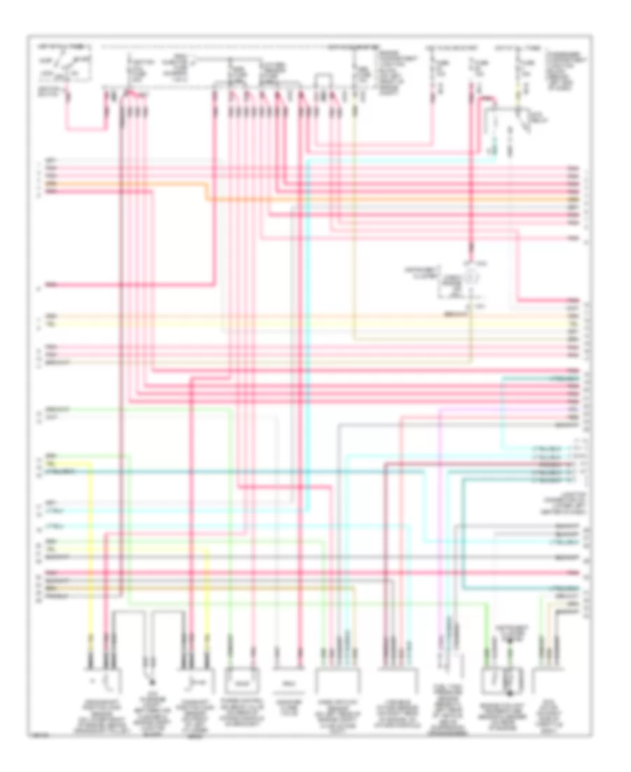
3.5L, Engine Performance Wiring Diagram (1 of 4) for Hyundai XG350 L 2004

List of elements for 3.5L, Engine Performance Wiring Diagram (1 of 4) for Hyundai XG350 L 2004:
- (top of engine)
- (top of engine) injectors
- (under center console, right of srs control module) g13
- A/c press sw
- A/c rly ctrl
- A/t fuse 20a
- A/t rly ctrl
- Afs sig
- Air conditioning system
- Aps source
- Ats sig
- B10
- C11
- C44-1
- C44-2
- Ccv sig
- Check eng ind
- Ckp sens sig
- Close sens
- Close(var int)
- Cmp sens sig
- Com area net
- Cruise control system
- Cruise control system cooling fans system
- Cruise ind
- Cruise sw ind
- Ecm fuse 10a
- Egr sol vlv
- Egr solenoid (on top right side of engine, on intake manifold)
- Electronic power steering system
- Engine comp- artment junction block (on left front of engine compt)
- Engine control relay (behind center of dash, on center support bracket)
- Eps
- Etc sens sig
- Ets rly ctrl
- F10
- F11
- Fan rly (hi)
- Fan rly (lo)
- Fuel pmp ctrl
- Fuel sender
- Fuel sender & fuel pump motor (beneath center of rear seat, in fuel tank)
- G07 (at left floorpanel crossmember)
- G08 (on left side of package shelf)
- G11 (on firewall, near throttle housing)
- G13 (under center console, right of srs control module)
- G14 (under center console, at right rear of srs control module)
- Gnd
- Hot at all times
- Ign coil 1
- Ign coil 2
- Ign coil 3
- Ign detect sig
- Ignition coil 1
- Ignition coil 2
- Ignition coil 3
- Ignition failure sensor (on upper left front of engine)
- Inj 1 ctrl
- Inj 2 ctrl
- Inj 3 ctrl
- Inj 4 ctrl
- Inj 5 ctrl
- Inj 6 ctrl
- Injector fuse 10a
- Instrument cluster system
- Jc01
- Limp home valve (on right rear of engine, near throttle body)
- Limp home vlv
- Main fuse 30a
- Memory pwr
- Nca
- O2s (heat)
- O2s (heating)
- Open sens
- Open(var int)
- P/n in
- Pcm (behind lower center of dash)
- Pcs vlv ctrl
- Pnk
- Power steering pressure switch (on power steering right side of engine)
- Pwr steering
- Red
- Rly ctrl
- Sens gnd
- Spark tim adj
- Starting/ charging system
- Tan
- To egr fuse (diagram 2 of 4)
- To spark plugs
- Trip
- Variable intake motor
- W/ immobilizer
- W/o immobilizer
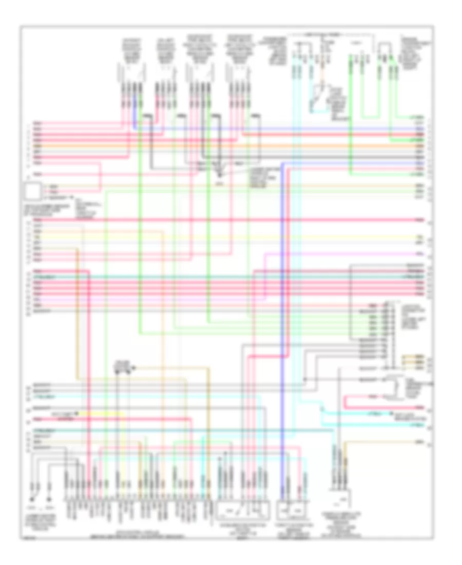
3.5L, Engine Performance Wiring Diagram (2 of 4) for Hyundai XG350 L 2004
List of elements for 3.5L, Engine Performance Wiring Diagram (2 of 4) for Hyundai XG350 L 2004:
- A11
- Abs fuse 10a
- Acc
- Camshaft position (cmp) sensor (on front of left cylinder head)
- Canister close valve
- Check engine ind (mil)
- Crankshaft position (ckp) sensor (on lower front of engine, behind crankshaft pulley)
- D10
- D11
- E10
- Egr fuse 15a
- Engine compartment junction block (on left front of engine compt)
- Engine coolant temperature sensor & sender (on rear of engine)
- Ets motor (on right side of throttle body)
- Ets relay
- From injector a fuse (diagram 1 of 4)
- Fuel tank pressure sensor (beneath left rear of vehicle, above suspension crossmember)
- Fuse 10a
- Fuse 15a
- G16 (in engine compt, between air cleaner & engine compt junction block)
- Hot at all times
- Hot in on or start
- I/p-b
- I/p-h
- I/p-j
- I18-1
- I18-2
- Ignition coil fuse 20a
- Ignition switch
- Instrument cluster
- Instrument cluster system
- Jc01
- Jm09
- Junction connector c41 (lower left center of dash)
- Lock off
- Mass air flow sensor (on left rear of engine compt, in air intake duct)
- Nca
- Oxygen sensor fuse 15a
- Passenger compartment junction block (behind left end of dash)
- Pnk
- Purge control solenoid valve (on rear of intake manifold, on bracket)
- Red
- Sender
- Sensor
- Start
- Variable intake sensor (on right rear of engine, on intake manifold)
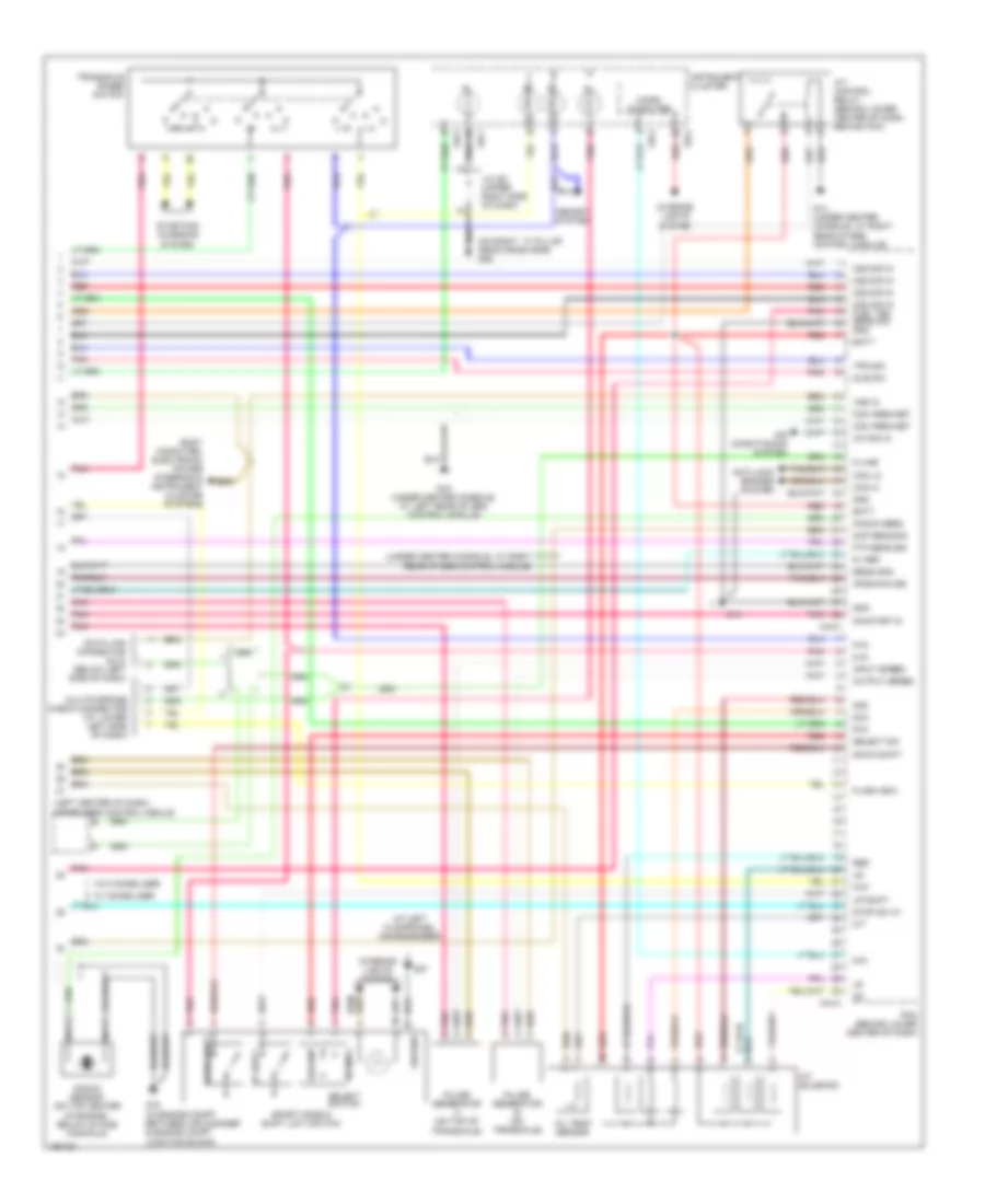
3.5L, Engine Performance Wiring Diagram (3 of 4) for Hyundai XG350 L 2004
List of elements for 3.5L, Engine Performance Wiring Diagram (3 of 4) for Hyundai XG350 L 2004:
- (on exhaust pipe, below left catalytic converter) rear oxygen sensor (b2/s2)
- (on exhaust pipe, below right catalytic converter) rear oxygen sensor (b1/s2)
- (on left exhaust manifold) oxygen sensor (b2/s1)
- (on right exhaust manifold) oxygen sensor (b1/s1)
- (under center console, right of srs control module)
- 5 v ref
- Accelerator position switch (on throttle body)
- Anti-lock brakes system
- Anti-theft system
- Aps sig
- Brake
- Coast gnd
- Coast in
- Com a net
- Cruise control system
- Ecm rly
- Engine compartment junction block (on left front of engine compt)
- Ets control module (behind center of dash, on support bracket)
- Ets mtr
- Fuel temperature sensor (in fuel tank)
- Fuse 15a
- G11 (on firewall, near throttle housing)
- G13
- G15
- Gnd
- Hot at all times
- I/p-e
- I/p-h
- I/p-k
- Jc01
- Jm09
- Junction connector c42 (lower left center of dash)
- Manifold absolute pressure (map)
- Mem pwr
- Mtr pwr
- Nca
- On/strt in
- P/n in
- Passenger compartment junction block (behind left end of dash)
- Pnk
- Red
- Sens gnd
- Sensor (on right side of engine, on intake manifold)
- Stop lamp switch (above brake pedal, on bracket)
- Stop sw
- Throttle position sensor (on left side of throttle body)
- Tps sig
- Vehicle speed sensor (on top right side of transaxle)
3.5L, Engine Performance Wiring Diagram (4 of 4) for Hyundai XG350 L 2004
List of elements for 3.5L, Engine Performance Wiring Diagram (4 of 4) for Hyundai XG350 L 2004:
- (at left floorpanel crossmember)
- (left center of dash) immobilizer control module
- (on right ``a" pillar near crash bar) g05
- (under center console, at right rear of srs control module)
- 2nd
- 5-in
- 5v ref
- A/c sig in
- A/t control relay (behind lower center of dash, behind pcm)
- A/t solenoid
- Air conditioning system
- Anti-lock brakes system
- Aps(main) sig
- Batt
- Body computer, electronic power steering & instrument cluster systems
- C44-3
- C44-4
- Can hi
- Can lo
- Com area net
- D-in
- Data link connector (dlc) (below left side of dash)
- Dcc
- Down shift
- Flash (eci)
- Ftp sens sig
- G07
- G14
- G14 (under center console, at right rear of srs control module)
- G15 (under center console, at left rear of srs control module)
- G16 (in engine compt between air cleaner & engine compt junction block)
- Gnd
- Ground
- I18-1
- I18-2
- I18-3
- Idle sw
- Input speed
- Instrument cluster
- Interior lights system
- J/c i28 (upper right side of dash)
- K-line
- Knock sens
- Knock sensor (on top center of engine, below intake manifold)
- Map sens sig
- Memory system
- Micro computer
- Multipurpose check connector (at lower left side of dash)
- N-in
- Nca
- Normal
- O/t
- O2s sig in
- O2s sig in fuel tem sens sig gnd
- Oil temp sensor
- On/start in
- Output speed
- P-in
- Pcm (behind lower center of dash)
- Pnk
- Pulse generator a (on top of transaxle)
- Pulse generator b (on transaxle)
- R-in
- Red
- Select
- Select sw
- Select switch
- Sens gnd
- Sport mode & shift limit switch
- Starting/ charging system
- Stop sw in
- Tps sig
- Transaxle range switch
- Up shift
- Vss in
- W/ immobilizer
- W/o immobilizer