ENGINE PERFORMANCE
3.5L
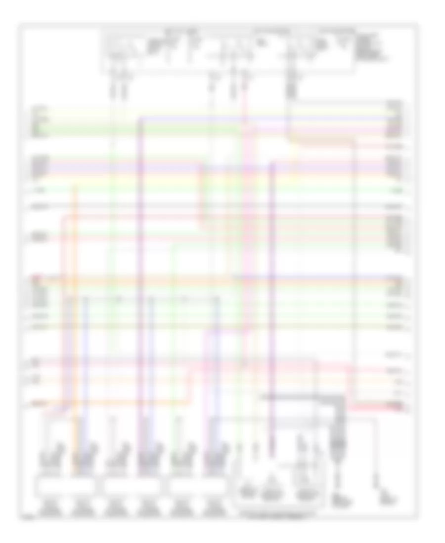
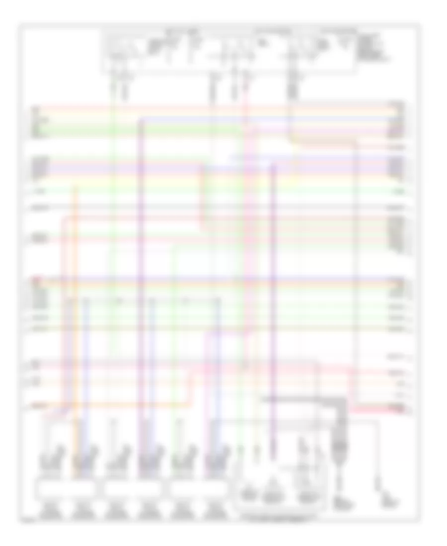
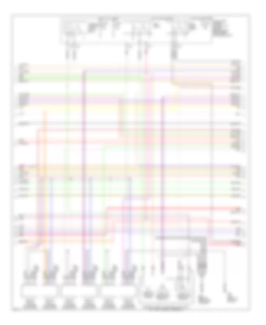
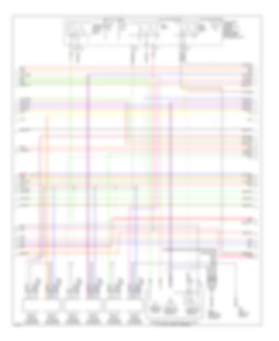
3.5L, Engine Performance Wiring Diagram, Early Production Coupe (1 of 4) for Infiniti G35 2004

List of elements for 3.5L, Engine Performance Wiring Diagram, Early Production Coupe (1 of 4) for Infiniti G35 2004:
- (behind right side of dash)
- Avcc
- Avcc2
- C-ivc (l)
- C-ivc (r)
- Combination meter
- Computer data lines system
- Condenser (right rear of engine)
- Crankshaft position sensor (pos) (on front of oil pan, below crankshaft pulley)
- Engine control module (behind right kick panel)
- Evap
- Evap canister purge volume control solenoid valve (on right side of intake manifold)
- F23 (top front of engine)
- Ftrps
- Fuel injector
- Fuse 10a
- Fuse block (j/b) (behind left kick panel)
- Gnd
- Hot in on or start
- Inj 1
- Inj 2
- Inj 3
- Inj 4
- Inj 5
- Inj 6
- Knk1
- Knock sensor (top center front of engine)
- M66
- M66 (behind right side of dash)
- Malfunction indicator lamp
- Motor1
- Motor2
- Nca
- Neutral
- O2hfl
- O2hfr
- O2hrl
- O2hrr
- O2sfl
- O2sfr
- O2srl
- Park/ neutral position switch (rear of trans- mission)
- Pdpres
- Phase lh
- Phase rh
- Pnk
- Pos
- Ps pres
- Qa+
- Red
- Refrigerant pressure sensor (on a/c liquid tank)
- Tps1
- Unified meter control unit
- V mot
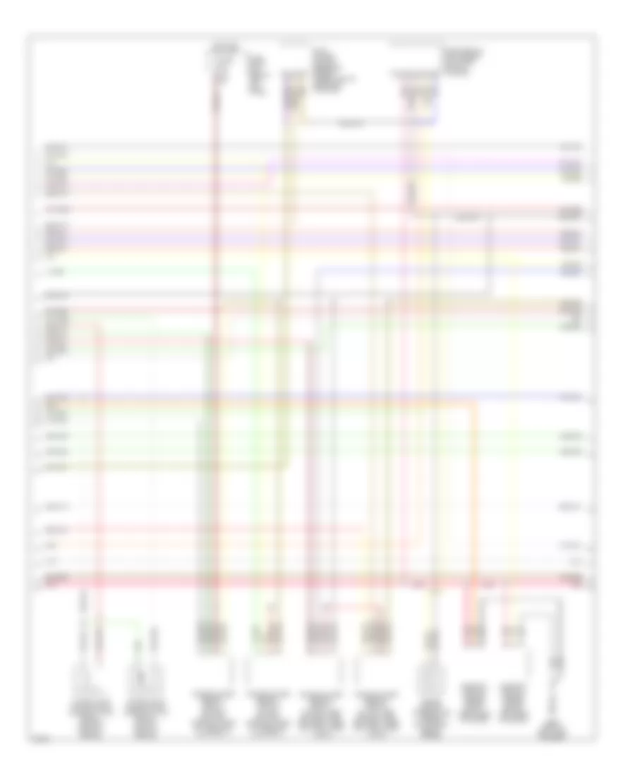
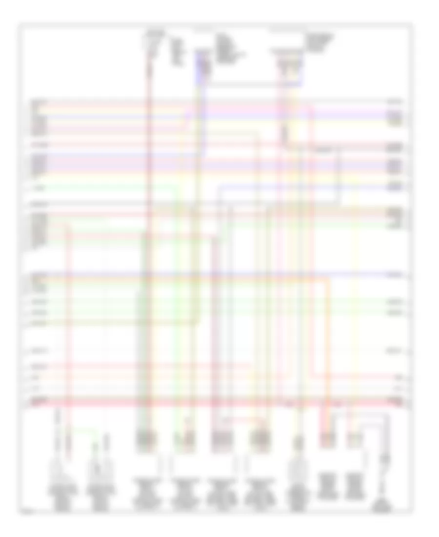
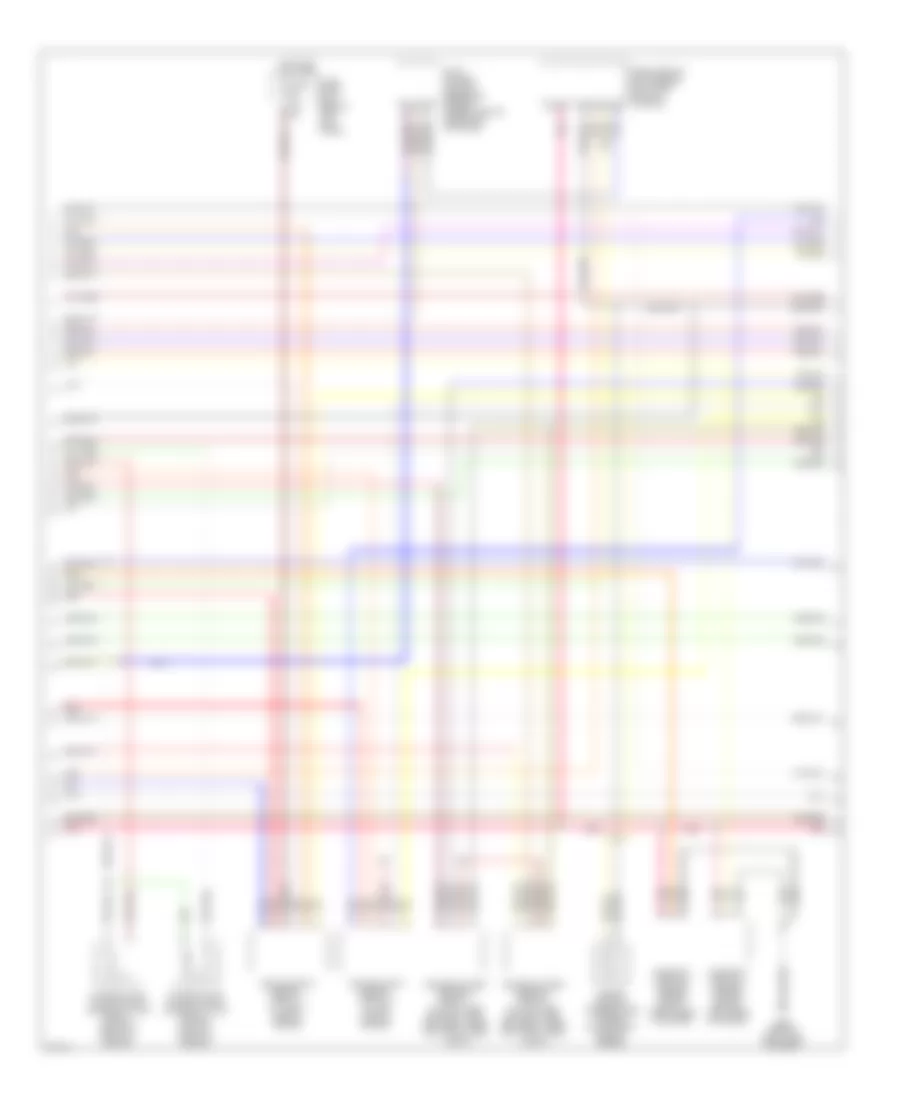
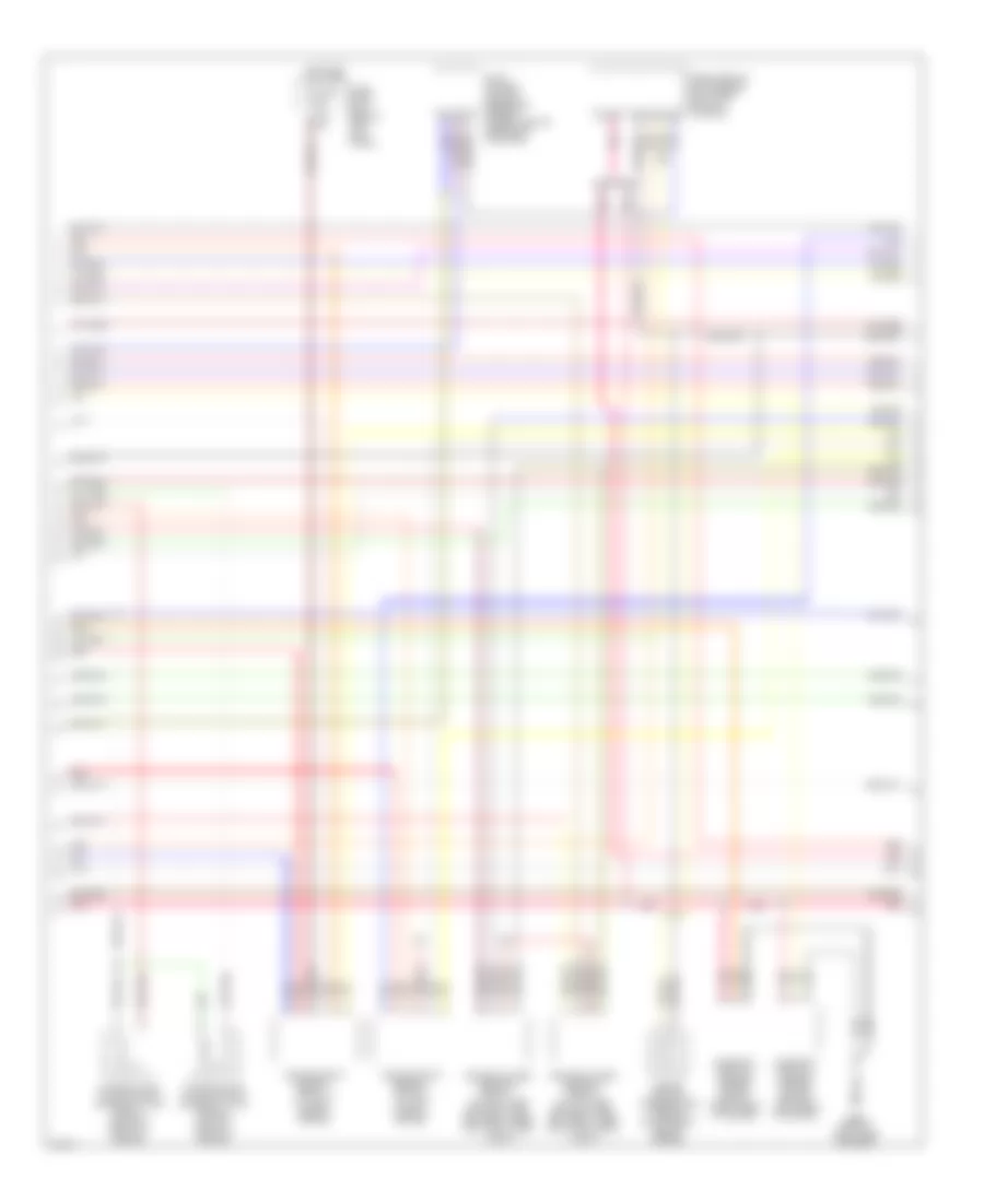
3.5L, Engine Performance Wiring Diagram, Early Production Coupe (2 of 4) for Infiniti G35 2004
List of elements for 3.5L, Engine Performance Wiring Diagram, Early Production Coupe (2 of 4) for Infiniti G35 2004:
- Ecm relay
- Electric throttle control actuator (on throttle body assembly)
- F23 (top front of engine)
- F31
- Fuel pump relay
- Fuse 15a
- Hot at all times
- Hot in on or start
- Ignition coil 1 (w/ power transistor)
- Ignition coil 2 (w/ power transistor)
- Ignition coil 3 (w/ power transistor)
- Ignition coil 4 (w/ power transistor)
- Ignition coil 5 (w/ power transistor)
- Ignition coil 6 (w/ power transistor)
- Intelligent power distribution module (engine room) (right rear of engine compt)
- M66 (behind right side of dash)
- Nca
- Nca nca
- Plug spark
- Pnk
- Spark plug
- Throttle control motor
- Throttle control motor relay
- Throttle position (tp) sensor 1
- Throttle position (tp) sensor 2
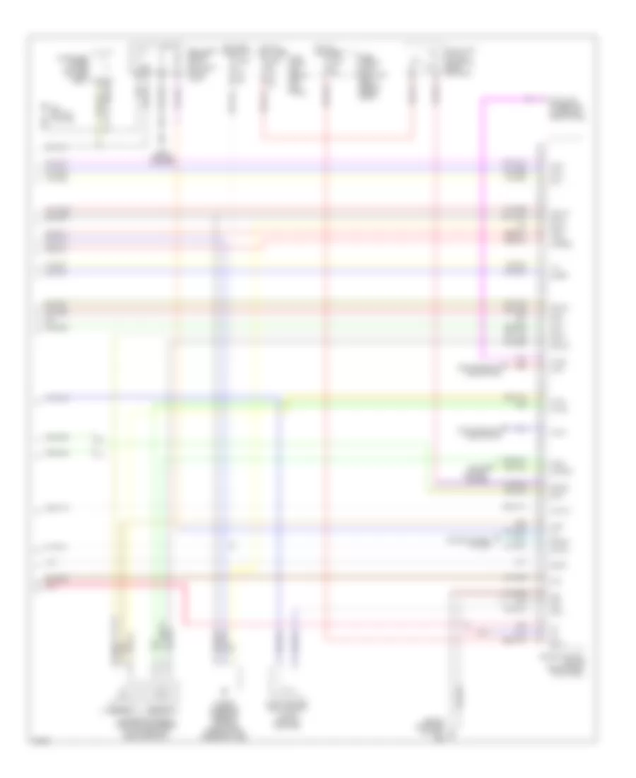
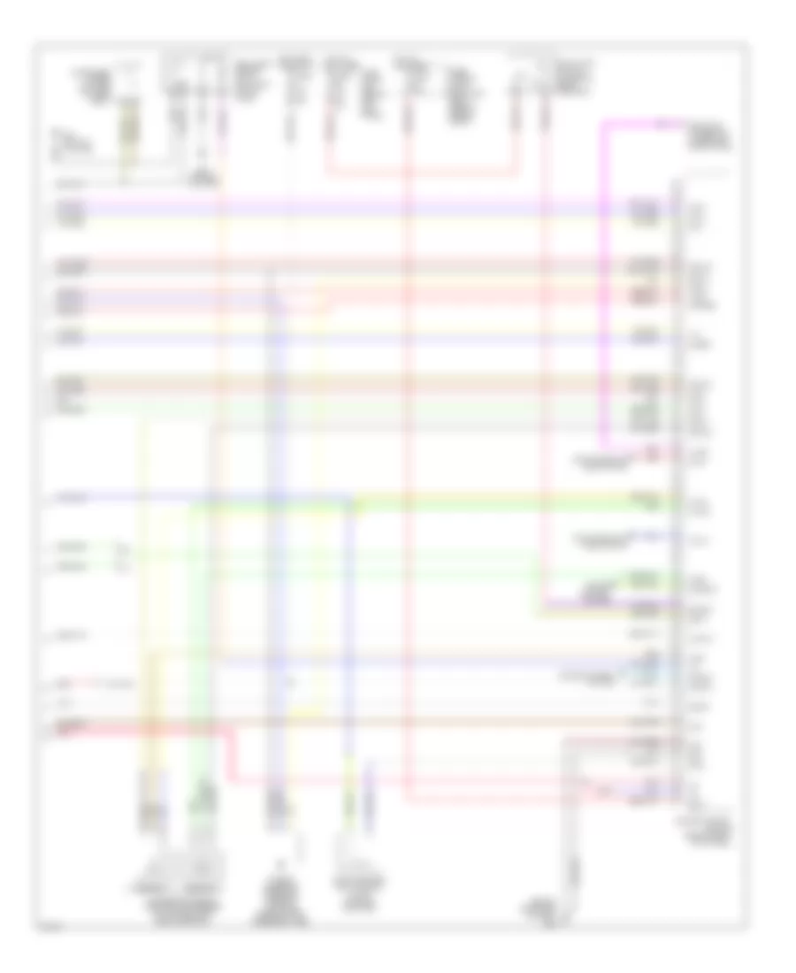
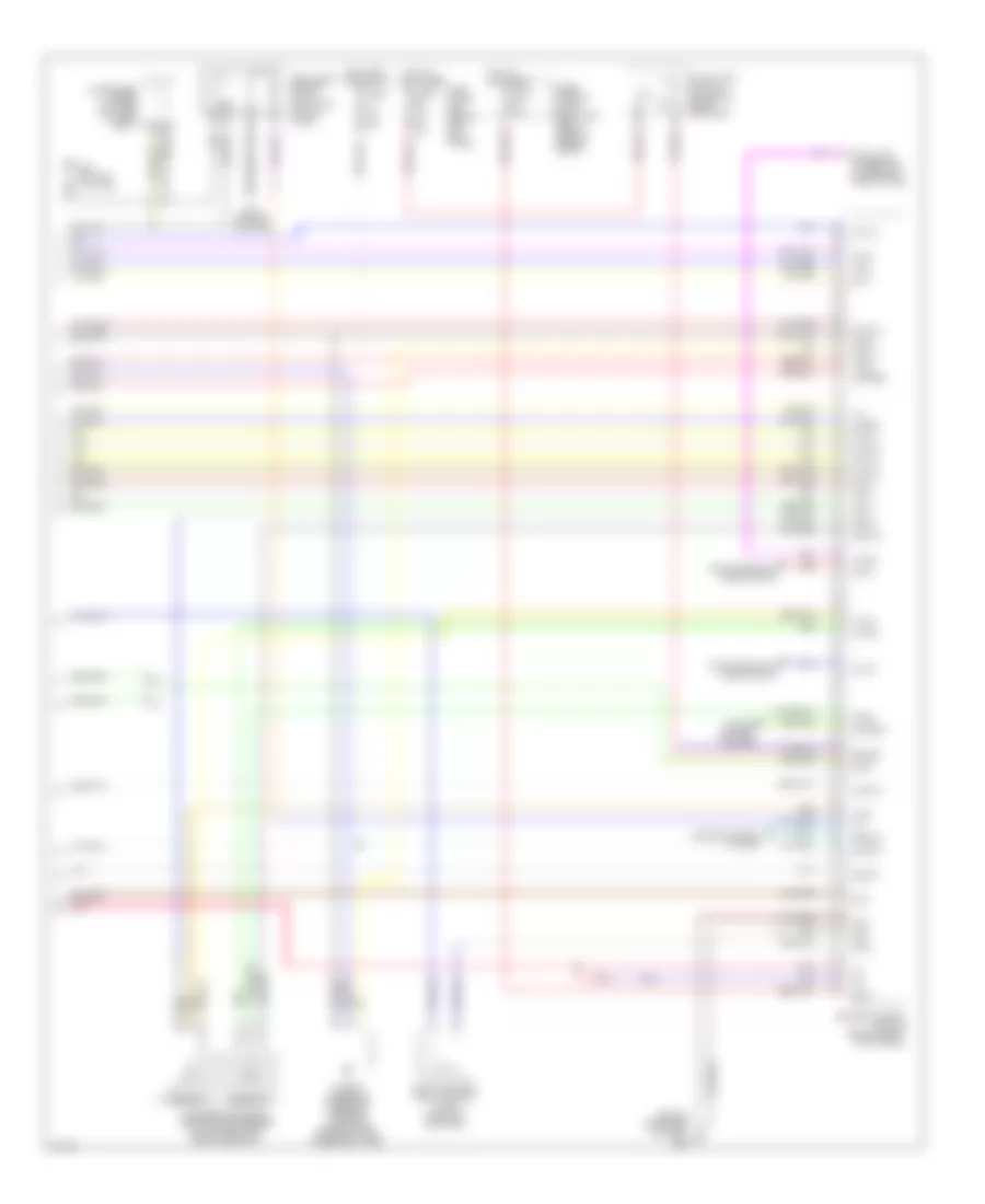
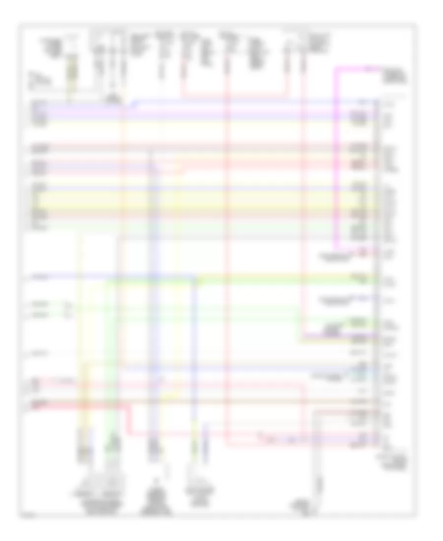
3.5L, Engine Performance Wiring Diagram, Early Production Coupe (3 of 4) for Infiniti G35 2004
List of elements for 3.5L, Engine Performance Wiring Diagram, Early Production Coupe (3 of 4) for Infiniti G35 2004:
- Camshaft position sensor (phase) (bank 1) (right rear of engine)
- Camshaft position sensor (phase) (bank 2) (left rear of engine)
- Engine coolant temperature sensor (on top right rear of engine)
- Evap control system pressure sensor (under vehicle, near evap canister)
- Fuse 15a
- Fuse block (j/b) (behind left kick panel)
- Heated oxygen sensor 1 (bank 1) (on right exhaust manifold, ahead of three way catalyst 1)
- Heated oxygen sensor 1 (bank 2) (on left exhaust manifold, ahead of three way catalyst 1)
- Heated oxygen sensor 2 (bank 1) (on right side exhaust pipe, between three way catalysts 1 and 2)
- Heated oxygen sensor 2 (bank 2) (on left side exhaust pipe, between three way catalysts 1 and 2)
- Hot in on or start
- Intake valve timing control solenoid valve (bank 1) (on right front of engine)
- Intake valve timing control solenoid valve (bank 2) (on left front of engine)
- M66 (behind right side of dash)
- Mass airflow (maf) sensor (on intake air duct housing)
- Pnk
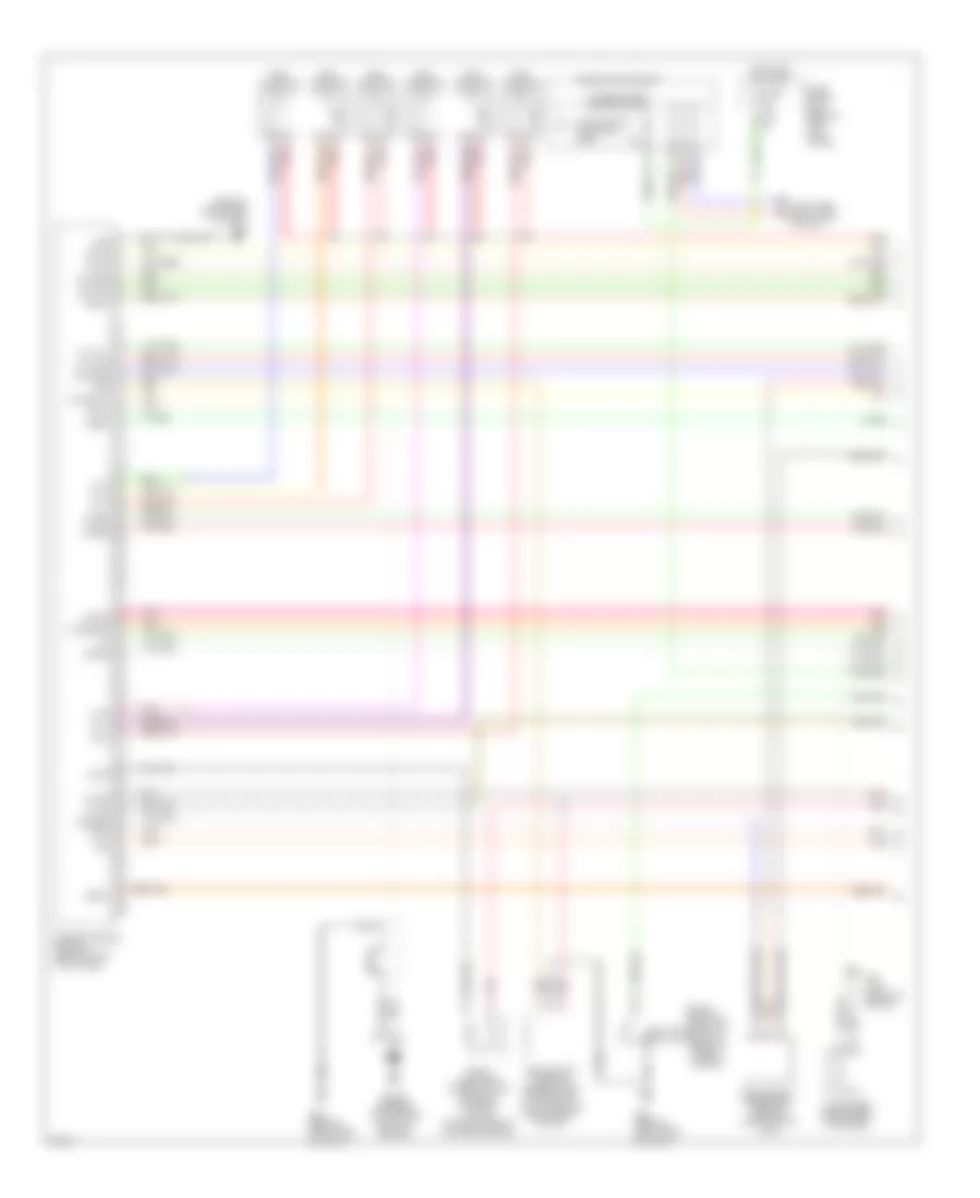
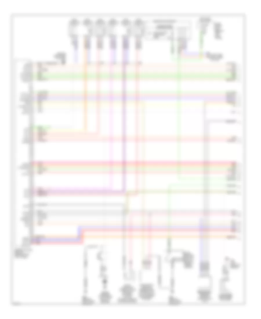
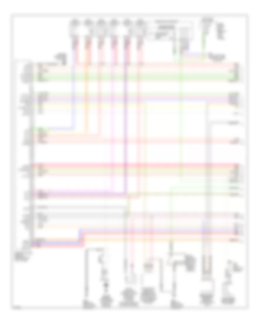
3.5L, Engine Performance Wiring Diagram, Early Production Coupe (4 of 4) for Infiniti G35 2004
List of elements for 3.5L, Engine Performance Wiring Diagram, Early Production Coupe (4 of 4) for Infiniti G35 2004:
- (behind right side of dash)
- 15a
- A/t
- Accelerator pedal position (app) sensor (on accelerator pedal bracket)
- Aps1
- Aps2
- Ascdsw
- Avcc
- Avcc2
- B29 (on left c pillar)
- Batt
- Bncsw
- Brake
- Can l
- Can-h
- Cdcv
- Computer data lines system
- Condenser (under left side of rear seat)
- Cruise control system
- Data link connector (lower left side of dash)
- E101
- Engine control module (behind right kick panel)
- Evap canister vent control valve (on evap canister)
- Fpr
- Fuel level sensor unit & fuel pump (in fuel tank)
- Fuse 10a
- Fuse 15a
- Fuse block (j/b) (behind left kick panel)
- Fuse, fusible link & relay box (right rear of engine compt)
- Gnd
- Gnd 02
- Gnd a
- Gnd a2
- Hot at all times
- Hot in on or start
- Ign 1
- Ign 2
- Ign 3
- Ign 4
- Ign 5
- Ign 6
- Ign sw
- Kline
- M/t
- M30 (behind cluster)
- M66
- Motrly
- Neut
- O2srr
- Pdpres
- Pnk
- Power steering pressure sensor (on power steering high pressure tube)
- Red
- Sensor 1
- Sensor 2
- Ssoff
- Stop lamp switch (on brake pedal bracket)
- Tps2
3.5L, Engine Performance Wiring Diagram, Early Production Sedan (1 of 4) for Infiniti G35 2004
List of elements for 3.5L, Engine Performance Wiring Diagram, Early Production Sedan (1 of 4) for Infiniti G35 2004:
- (behind right side of dash)
- Avcc
- Avcc2
- C-ivc (l)
- C-ivc (r)
- Combination meter
- Computer data lines system
- Condenser (right rear of engine)
- Crankshaft position sensor (pos) (on front of oil pan, below crankshaft pulley)
- Engine control module (behind right kick panel)
- Evap
- Evap canister purge volume control solenoid valve (on right side of intake manifold)
- F23 (top front of engine)
- Ftrps
- Fuel injector
- Fuse 10a
- Fuse block (j/b) (behind left kick panel)
- Gnd
- Hot in on or start
- Inj 1
- Inj 2
- Inj 3
- Inj 4
- Inj 5
- Inj 6
- Knk1
- Knock sensor (top center front of engine)
- M66
- M66 (behind right side of dash)
- Malfunction indicator lamp
- Motor1
- Motor2
- Nca
- Neutral
- O2hfl
- O2hfr
- O2hrl
- O2hrr
- O2sfl
- O2sfr
- O2srl
- Park/ neutral position switch (rear of trans- mission)
- Pdpres
- Phase lh
- Phase rh
- Pnk
- Pos
- Ps pres
- Qa+
- Red
- Refrigerant pressure sensor (on a/c liquid tank)
- Tps1
- Unified meter control unit
- V mot
3.5L, Engine Performance Wiring Diagram, Early Production Sedan (2 of 4) for Infiniti G35 2004
List of elements for 3.5L, Engine Performance Wiring Diagram, Early Production Sedan (2 of 4) for Infiniti G35 2004:
- Ecm relay
- Electric throttle control actuator (on throttle body assembly)
- F23 (top front of engine)
- F31
- Fuel pump relay
- Fuse 15a
- Hot at all times
- Hot in on or start
- Ignition coil 1 (w/ power transistor)
- Ignition coil 2 (w/ power transistor)
- Ignition coil 3 (w/ power transistor)
- Ignition coil 4 (w/ power transistor)
- Ignition coil 5 (w/ power transistor)
- Ignition coil 6 (w/ power transistor)
- Intelligent power distribution module (engine room) (right rear of engine compt)
- M66 (behind right side of dash)
- Nca
- Nca nca
- Plug spark
- Pnk
- Red
- Spark plug
- Throttle control motor
- Throttle control motor relay
- Throttle position (tp) sensor 1
- Throttle position (tp) sensor 2
3.5L, Engine Performance Wiring Diagram, Early Production Sedan (3 of 4) for Infiniti G35 2004
List of elements for 3.5L, Engine Performance Wiring Diagram, Early Production Sedan (3 of 4) for Infiniti G35 2004:
- Camshaft position sensor (phase) (bank 1) (right rear of engine)
- Camshaft position sensor (phase) (bank 2) (left rear of engine)
- Engine coolant temperature sensor (on top right rear of engine)
- Evap control system pressure sensor (under vehicle, near evap canister)
- Fuse 15a
- Fuse block (j/b) (behind left kick panel)
- Heated oxygen sensor 1 (bank 1) (on right exhaust manifold, ahead of three way catalyst 1)
- Heated oxygen sensor 1 (bank 2) (on left exhaust manifold, ahead of three way catalyst 1)
- Heated oxygen sensor 2 (bank 1) (on right side exhaust pipe, between three way catalysts 1 and 2)
- Heated oxygen sensor 2 (bank 2) (on left side exhaust pipe, between three way catalysts 1 and 2)
- Hot in on or start
- Intake valve timing control solenoid valve (bank 1) (on right front of engine)
- Intake valve timing control solenoid valve (bank 2) (on left front of engine)
- M66 (behind right side of dash)
- Mass airflow (maf) sensor (on intake air duct housing)
- Pnk
- Red
3.5L, Engine Performance Wiring Diagram, Early Production Sedan (4 of 4) for Infiniti G35 2004
List of elements for 3.5L, Engine Performance Wiring Diagram, Early Production Sedan (4 of 4) for Infiniti G35 2004:
- (behind right side of dash)
- 15a
- A/t
- Accelerator pedal position (app) sensor (on accelerator pedal bracket)
- Aps1
- Aps2
- Ascdsw
- Avcc
- Avcc2
- B29 (on left c pillar)
- Batt
- Bncsw
- Brake
- Can l
- Can-h
- Cdcv
- Computer data lines system
- Condenser (under left side of rear seat)
- Cruise control system
- Data link connector (lower left side of dash)
- E101
- Engine control module (behind right kick panel)
- Evap canister vent control valve (on evap canister)
- Fpr
- Fuel level sensor unit & fuel pump (in fuel tank)
- Fuse 10a
- Fuse 15a
- Fuse block (j/b) (behind left kick panel)
- Fuse, fusible link & relay box (right rear of engine compt)
- Gnd
- Gnd 02
- Gnd a
- Gnd a2
- Hot at all times
- Hot in on or start
- Ign 1
- Ign 2
- Ign 3
- Ign 4
- Ign 5
- Ign 6
- Ign sw
- Kline
- M/t
- M30 (behind cluster)
- M66
- Motrly
- Neut
- O2srr
- Pdpres
- Pnk
- Power steering pressure sensor (on power steering high pressure tube)
- Red
- Sensor 1
- Sensor 2
- Ssoff
- Stop lamp switch (on brake pedal bracket)
- Tps2
3.5L, Engine Performance Wiring Diagram, Late Production Coupe (1 of 4) for Infiniti G35 2004
List of elements for 3.5L, Engine Performance Wiring Diagram, Late Production Coupe (1 of 4) for Infiniti G35 2004:
- (behind right side of dash)
- Af-h1
- Af-h2
- Af-ip1
- Af-un1
- Af-vm1
- Avcc
- Avcc2
- C-ivc (l)
- C-ivc (r)
- Combination meter
- Computer data lines system
- Condenser (right rear of engine)
- Crankshaft position sensor (pos) (on front of oil pan, below crankshaft pulley)
- Engine control module (behind right kick panel)
- Evap
- Evap canister purge volume control solenoid valve (on right side of intake manifold)
- F23 (top front of engine)
- Ftrps
- Fuel injector
- Fuse 10a
- Fuse block (j/b) (behind left kick panel)
- Gnd
- Hot in on or start
- Inj 1
- Inj 2
- Inj 3
- Inj 4
- Inj 5
- Inj 6
- Knk1
- Knock sensor (top center front of engine)
- M66
- M66 (behind right side of dash)
- Malfunction indicator lamp
- Motor1
- Motor2
- Nca
- Neutral
- O2hrl
- O2hrr
- O2srl
- Park/ neutral position switch (rear of trans- mission)
- Pdpres
- Phase lh
- Phase rh
- Pnk
- Pos
- Ps pres
- Qa+
- Red
- Refrigerant pressure sensor (on a/c liquid tank)
- Tps1
- Unified meter control unit
- V mot
3.5L, Engine Performance Wiring Diagram, Late Production Coupe (2 of 4) for Infiniti G35 2004
List of elements for 3.5L, Engine Performance Wiring Diagram, Late Production Coupe (2 of 4) for Infiniti G35 2004:
- Ecm relay
- Electric throttle control actuator (on throttle body assembly)
- F23 (top front of engine)
- F31
- Fuel pump relay
- Fuse 15a
- Hot at all times
- Hot in on or start
- Ignition coil 1 (w/ power transistor)
- Ignition coil 2 (w/ power transistor)
- Ignition coil 3 (w/ power transistor)
- Ignition coil 4 (w/ power transistor)
- Ignition coil 5 (w/ power transistor)
- Ignition coil 6 (w/ power transistor)
- Intelligent power distribution module (engine room) (right rear of engine compt)
- M66 (behind right side of dash)
- Nca
- Nca nca
- Plug spark
- Pnk
- Red
- Spark plug
- Throttle control motor
- Throttle control motor relay
- Throttle position (tp) sensor 1
- Throttle position (tp) sensor 2
3.5L, Engine Performance Wiring Diagram, Late Production Coupe (3 of 4) for Infiniti G35 2004
List of elements for 3.5L, Engine Performance Wiring Diagram, Late Production Coupe (3 of 4) for Infiniti G35 2004:
- Air fuel ratio sensor 1 (bank 1) (at right side of engine)
- Air fuel ratio sensor 1 (bank 2) (at left side of engine)
- Camshaft position sensor (phase) (bank 1) (right rear of engine)
- Camshaft position sensor (phase) (bank 2) (left rear of engine)
- Engine coolant temperature sensor (on top right rear of engine)
- Evap control system pressure sensor (under vehicle, near evap canister)
- Fuse 15a
- Fuse block (j/b) (behind left kick panel)
- Heated oxygen sensor 2 (bank 1) (on right side exhaust pipe, between three way catalysts 1 and 2)
- Heated oxygen sensor 2 (bank 2) (on left side exhaust pipe, between three way catalysts 1 and 2)
- Hot in on or start
- Intake valve timing control solenoid valve (bank 1) (on right front of engine)
- Intake valve timing control solenoid valve (bank 2) (on left front of engine)
- M66 (behind right side of dash)
- Mass airflow (maf) sensor (on intake air duct housing)
- Pnk
- Red
3.5L, Engine Performance Wiring Diagram, Late Production Coupe (4 of 4) for Infiniti G35 2004
List of elements for 3.5L, Engine Performance Wiring Diagram, Late Production Coupe (4 of 4) for Infiniti G35 2004:
- (behind right side of dash)
- 15a
- A/t
- Accelerator pedal position (app) sensor (on accelerator pedal bracket)
- Af-ia1
- Af-ia2
- Af-ip2
- Af-un2
- Aps1
- Aps2
- Ascdsw
- Avcc
- Avcc2
- B29 (on left c pillar)
- Batt
- Bncsw
- Brake
- Can l
- Can-h
- Cdcv
- Computer data lines system
- Condenser (under left side of rear seat)
- Cruise control system
- Data link connector (lower left side of dash)
- E101
- Engine control module (behind right kick panel)
- Evap canister vent control valve (on evap canister)
- Fpr
- Fuel level sensor unit & fuel pump (in fuel tank)
- Fuse 10a
- Fuse 15a
- Fuse block (j/b) (behind left kick panel)
- Fuse, fusible link & relay box (right rear of engine compt)
- Gnd
- Gnd 02
- Gnd a
- Gnd a2
- Hot at all times
- Hot in on or start
- Ign 1
- Ign 2
- Ign 3
- Ign 4
- Ign 5
- Ign 6
- Ign sw
- Kline
- M/t
- M30 (behind cluster)
- M66
- Motrly
- Neut
- O2srr
- Pdpres
- Pnk
- Power steering pressure sensor (on power steering high pressure tube)
- Red
- Sensor 1
- Sensor 2
- Ssoff
- Stop lamp switch (on brake pedal bracket)
- Tps2
3.5L, Engine Performance Wiring Diagram, Late Production Sedan (1 of 4) for Infiniti G35 2004
List of elements for 3.5L, Engine Performance Wiring Diagram, Late Production Sedan (1 of 4) for Infiniti G35 2004:
- (behind right side of dash)
- Af-h1
- Af-h2
- Af-ip1
- Af-un1
- Af-vm1
- Avcc
- Avcc2
- C-ivc (l)
- C-ivc (r)
- Combination meter
- Computer data lines system
- Condenser (right rear of engine)
- Crankshaft position sensor (pos) (on front of oil pan, below crankshaft pulley)
- Engine control module (behind right kick panel)
- Evap
- Evap canister purge volume control solenoid valve (on right side of intake manifold)
- F23 (top front of engine)
- Ftrps
- Fuel injector
- Fuse 10a
- Fuse block (j/b) (behind left kick panel)
- Gnd
- Hot in on or start
- Inj 1
- Inj 2
- Inj 3
- Inj 4
- Inj 5
- Inj 6
- Knk1
- Knock sensor (top center front of engine)
- M66
- M66 (behind right side of dash)
- Malfunction indicator lamp
- Motor1
- Motor2
- Nca
- Neutral
- O2hrl
- O2hrr
- O2srl
- Park/ neutral position switch (rear of trans- mission)
- Pdpres
- Phase lh
- Phase rh
- Pnk
- Pos
- Ps pres
- Qa+
- Red
- Refrigerant pressure sensor (on a/c liquid tank)
- Tps1
- Unified meter control unit
- V mot
3.5L, Engine Performance Wiring Diagram, Late Production Sedan (2 of 4) for Infiniti G35 2004
List of elements for 3.5L, Engine Performance Wiring Diagram, Late Production Sedan (2 of 4) for Infiniti G35 2004:
- Ecm relay
- Electric throttle control actuator (on throttle body assembly)
- F23 (top front of engine)
- F31
- Fuel pump relay
- Fuse 15a
- Hot at all times
- Hot in on or start
- Ignition coil 1 (w/ power transistor)
- Ignition coil 2 (w/ power transistor)
- Ignition coil 3 (w/ power transistor)
- Ignition coil 4 (w/ power transistor)
- Ignition coil 5 (w/ power transistor)
- Ignition coil 6 (w/ power transistor)
- Intelligent power distribution module (engine room) (right rear of engine compt)
- M66 (behind right side of dash)
- Nca
- Nca nca
- Plug spark
- Pnk
- Red
- Spark plug
- Throttle control motor
- Throttle control motor relay
- Throttle position (tp) sensor 1
- Throttle position (tp) sensor 2
3.5L, Engine Performance Wiring Diagram, Late Production Sedan (3 of 4) for Infiniti G35 2004
List of elements for 3.5L, Engine Performance Wiring Diagram, Late Production Sedan (3 of 4) for Infiniti G35 2004:
- Air fuel ratio sensor 1 (bank 1) (at right side of engine)
- Air fuel ratio sensor 1 (bank 2) (at left side of engine)
- Awd
- Camshaft position sensor (phase) (bank 1) (right rear of engine)
- Camshaft position sensor (phase) (bank 2) (left rear of engine)
- Engine coolant temperature sensor (on top right rear of engine)
- Evap control system pressure sensor (under vehicle, near evap canister)
- Fuse 15a
- Fuse block (j/b) (behind left kick panel)
- Heated oxygen sensor 2 (bank 1) (on right side exhaust pipe, between three way catalysts 1 and 2)
- Heated oxygen sensor 2 (bank 2) (on left side exhaust pipe, between three way catalysts 1 and 2)
- Hot in on or start
- Intake valve timing control solenoid valve (bank 1) (on right front of engine)
- Intake valve timing control solenoid valve (bank 2) (on left front of engine)
- M66 (behind right side of dash)
- Mass airflow (maf) sensor (on intake air duct housing)
- Pnk
- Red
- Rwd
3.5L, Engine Performance Wiring Diagram, Late Production Sedan (4 of 4) for Infiniti G35 2004
List of elements for 3.5L, Engine Performance Wiring Diagram, Late Production Sedan (4 of 4) for Infiniti G35 2004:
- (behind right side of dash)
- 15a
- A/t
- Accelerator pedal position (app) sensor (on accelerator pedal bracket)
- Af-ia1
- Af-ia2
- Af-ip2
- Af-un2
- Aps1
- Aps2
- Ascdsw
- Avcc
- Avcc2
- B29 (on left c pillar)
- Batt
- Bncsw
- Brake
- Can l
- Can-h
- Cdcv
- Computer data lines system
- Condenser (under left side of rear seat)
- Cruise control system
- Data link connector (lower left side of dash)
- E101
- Engine control module (behind right kick panel)
- Evap canister vent control valve (on evap canister)
- Fpr
- Fuel level sensor unit & fuel pump (in fuel tank)
- Fuse 10a
- Fuse 15a
- Fuse block (j/b) (behind left kick panel)
- Fuse, fusible link & relay box (right rear of engine compt)
- Gnd
- Gnd 02
- Gnd a
- Gnd a2
- Hot at all times
- Hot in on or start
- Ign 1
- Ign 2
- Ign 3
- Ign 4
- Ign 5
- Ign 6
- Ign sw
- Kline
- M/t
- M30 (behind cluster)
- M66
- Motrly
- Neut
- O2srr
- Pdpres
- Pnk
- Power steering pressure sensor (on power steering high pressure tube)
- Red
- Sensor 1
- Sensor 2
- Ssoff
- Stop lamp switch (on brake pedal bracket)
- Tps2