ENGINE PERFORMANCE
3.7L
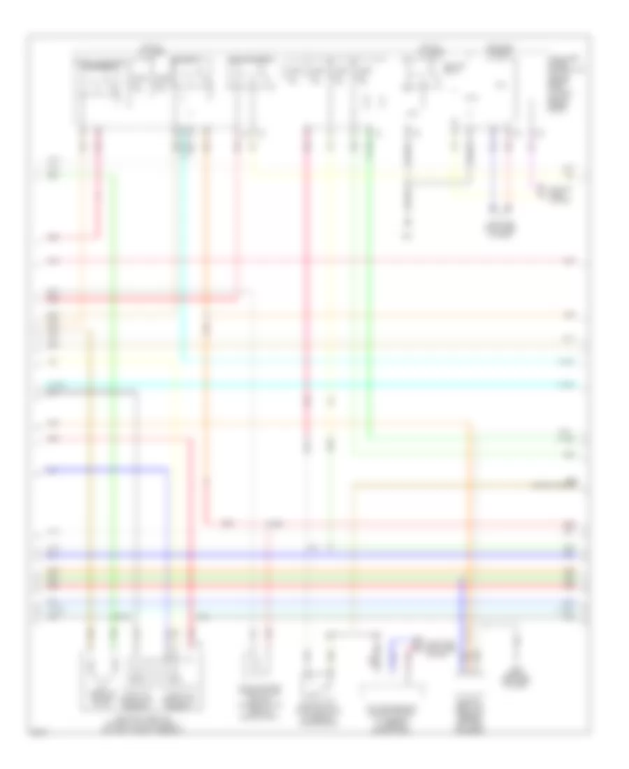
3.7L, Engine Performance Wiring Diagram (1 of 5) for Infiniti G37 Sport 2008

List of elements for 3.7L, Engine Performance Wiring Diagram (1 of 5) for Infiniti G37 Sport 2008:
- (ignition coils: 1, 3 & 5 top of cylinder bank 1) (ignition coils: 2, 4 & 6 top of cylinder bank 2)
- Abort
- Af+1
- Af-1
- Afh1
- Afh2
- Avcc1-phase#1
- Avcc1-tps-b1
- Avcc1-tps-b2
- Avcc2-phase#2
- Avcc2-pos
- Avcc2/intpress
- Brake booster pressure sensor (on brake fluid reservoir)
- Close
- Computer data lines system
- Condenser (right rear of engine)
- Crankshaft position sensor (pos) (right rear of engine)
- Cvtc#1
- Cvtc#2
- Electric throttle control actuator (bank 2) (on throttle body assembly)
- Eng can-hi
- Eng can-li
- Engine control module (under right end of dash)
- Evap
- F101
- F34 (right front of engine)
- Fpr
- Gnd
- Gnd-pos
- Gnda-tps-b1
- Gnda-tps-b2
- Gnda/intpres
- Ign #5
- Ign#1
- Ign#2
- Ign#3
- Ign#4
- Ign#6
- Ignition coil 1 (w/ power transistor)
- Ignition coil 2 (w/ power transistor)
- Ignition coil 3 (w/ power transistor)
- Ignition coil 4 (w/ power transistor)
- Ignition coil 5 (w/ power transistor)
- Ignition coil 6 (w/ power transistor)
- Ignsw
- Intake valve timing control solenoid valve (bank 1) (front of cylinder bank 1)
- Intake valve timing control solenoid valve (bank 2) (front of cylinder bank 2)
- Intppresi
- M95 (behind right side of dash)
- Motor-b1
- Motor1-b2
- Motor2-b1
- Motor2-b2
- Motrly-b1
- Mvpres
- Nca
- O2hr1
- O2hr2
- Open
- Phase#1
- Phase#2
- Plug spark
- Pnk
- Pos
- Red
- Spark plug
- Ssoff
- Throttle control motor
- Throttle position (tp) sensor 1
- Throttle position (tp) sensor 2
- Tps1-b1
- Tps1-b2
- Tps2-b1
- Tps2-b2
- Vmot-b1
- Vmot-b2
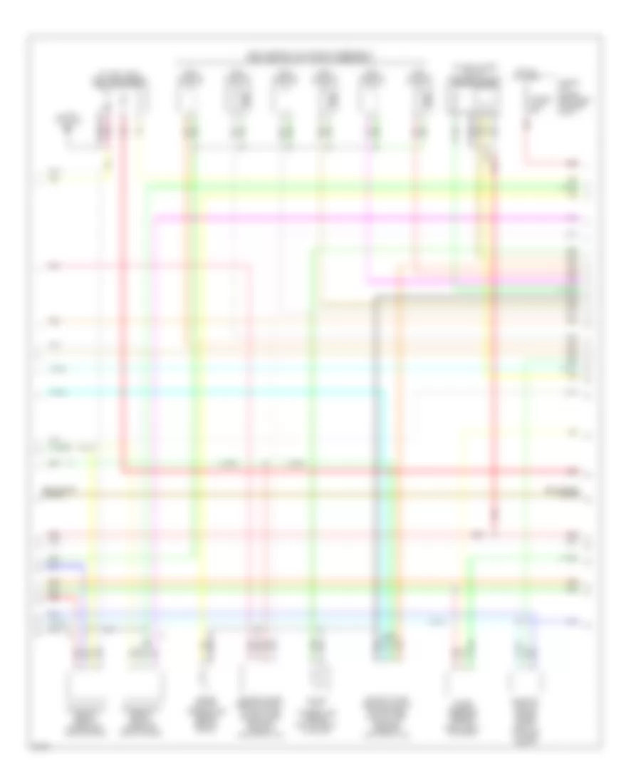
3.7L, Engine Performance Wiring Diagram (2 of 5) for Infiniti G37 Sport 2008
List of elements for 3.7L, Engine Performance Wiring Diagram (2 of 5) for Infiniti G37 Sport 2008:
- A/t
- A/t assembly (at rear of engine compt)
- Close
- Computer data lines system
- Cooling fans system
- Cpu
- E22
- Ecm relay
- Electric throttle control actuator (bank 1) (on throttle body assembly)
- Evap canister purge volume control solenoid valve (rear of engine compt)
- Fuel pump relay
- Fuse 10a
- Fuse 15a
- Hot at all times
- Hot in on or start
- Ignition relay
- Intelligent power distribution module (engine room) (at right rear of engine compt)
- M/t
- M95 (behind right side of dash)
- Manifold absolute pressure sensor (left rear of engine)
- Nca
- Open
- Park/neutral position switch (at rear of transmission)
- Pnk
- Red
- Tcm (transmission control module)
- Throttle control motor
- Throttle control motor relay
- Throttle position (tp) sensor 1
- Throttle position (tp) sensor 2
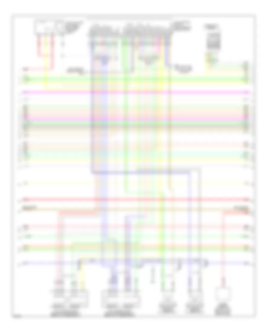
3.7L, Engine Performance Wiring Diagram (3 of 5) for Infiniti G37 Sport 2008
List of elements for 3.7L, Engine Performance Wiring Diagram (3 of 5) for Infiniti G37 Sport 2008:
- (at fuel tank) fuel level sensor unit & fuel pump
- (fuel injector 1,3 & 5 top of cylinder bank 1) (fuel injector 2,4 & 6 top of cylinder bank 1)
- (in left "c" pillar) b24
- (on left intake air duct) mass airflow (maf) sensor (bank2)
- Air fuel ratio sensor 1 (bank 1) (under right side of engine)
- Air fuel ratio sensor 1 (bank 2) (under left side of engine)
- Camshaft position sensor (phase) (bank 2) (front of cylinder bank 2)
- Engine coolant temperature sensor (rear of engine)
- Engine oil temperature sensor (bottom front of engine)
- Fuel injector
- Fusible link holder (right rear of engine compt)
- Fusible link n 50a
- Heated oxygen sensor 2 (bank 1) (on right side exhaust pipe, between three-way catalysts 1 & 2)
- Heated oxygen sensor 2 (bank 2) (on left side exhaust pipe, between three-way catalysts 1 & 2)
- Hot at all times
- Nca
- Pnk
- Power steering pressure sensor (right front of engine)
- Red
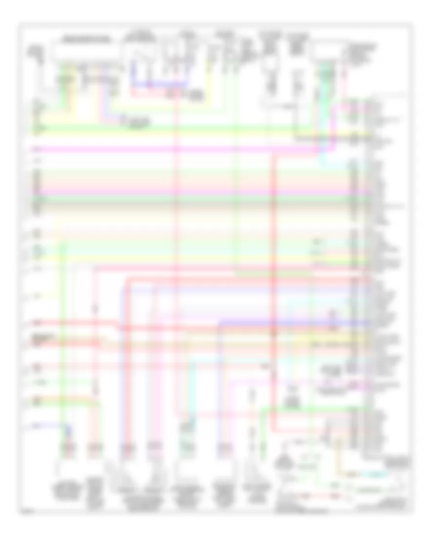
3.7L, Engine Performance Wiring Diagram (4 of 5) for Infiniti G37 Sport 2008
List of elements for 3.7L, Engine Performance Wiring Diagram (4 of 5) for Infiniti G37 Sport 2008:
- (left rear of engine compt) e46
- Abort
- Agnd1
- Agnd2
- Agnd3
- Agnd4
- Avcc1
- Avcc2
- Avcc3
- Avcc4
- Can h
- Can l
- Combination meter
- Comm-amp->lcd
- Comm-amp->mtr
- Comm-lcd->amp
- Comm-mtr->amp
- Computer data lines system
- E22
- M-rly
- Motor l 1
- Motor l 2
- Motor r1
- Motor r2
- Nca
- Pgnd l
- Pnk
- Power steering control unit (behind right side of dash)
- Red
- Sensor 1
- Sensor 2
- V-mot (r)
- Vel s-r2
- Vel/s-l1
- Vel/s-r1
- Vmot l
- Vvel actuator motor (bank 1) (rear of cylinder bank 1)
- Vvel actuator motor (bank 2) (rear of cylinder bank 2)
- Vvel actuator motor relay (right rear of engine compt)
- Vvel control module (right rear of engine compt)
- Vvel control shaft position sensor (bank 1) (rear of cylinder bank 1)
- Vvel control shaft position sensor (bank 2) (rear of cylinder bank 2)
3.7L, Engine Performance Wiring Diagram (5 of 5) for Infiniti G37 Sport 2008
List of elements for 3.7L, Engine Performance Wiring Diagram (5 of 5) for Infiniti G37 Sport 2008:
- (behind center of dash) unified meter & amplifier
- (behind left end of dash) m11
- (on brake pedal bracket) stop lamp switch
- (or red)
- (top center of cylinder bank 1) knock sensor (bank 1)
- (top center of cylinder bank 1) knock sensor (bank 2)
- A/t
- Accelerator pedal position (app) sensor (on accelerator pedal bracket)
- Af+2
- Af-2
- Aps1
- Aps2
- Ascd or icc brake switch (on brake pedal bracket)
- Ascd or icc clutch switch (on clutch pedal bracket)
- Ascdsw
- Avcc1-aps1
- Avcc2-aps2
- Avcc2-ftprs
- Avcc2-pdpres
- Batt
- Battery current sensor (right rear of engine compt, at battery)
- Bncsw
- Brake
- Camshaft position sensor (phase) (bank 1) (front of cylinder bank 1)
- Cdcv
- Computer data lines system
- Cruise control system
- Cursen
- E103
- Engine control module (under right end of dash)
- Evap canister vent control valve (on evap canister)
- Evap control system pressure sensor (under vehicle, near evap canister)
- F102
- Ftprs
- Fuse 10a
- Fuse block (j/b) (behind left kick panel)
- Gnd
- Gnd-phase#2
- Gnda
- Gnda-aps1
- Gnda-aps2
- Gnda-ascdsw
- Gnda-cursen
- Gnda-ftprs
- Gnda-knk
- Gnda-o2_tw_to
- Gnda-pdpres
- Gnda-qa1_ta1
- Gnda-qa2_ta2
- Hot at all times
- Hot in on or start
- Inj#1
- Inj#2
- Inj#3
- Inj#4
- Inj#5
- Inj#6
- Kline
- Knk1
- Knk2
- M/t
- M107
- M66
- M67
- M95 (behind right side of dash)
- Mass airflow (maf) sensor (bank 1) (on right intake air duct)
- Nca
- Neut-h
- O2sr2
- Osr1
- Pdpres
- Pnk
- Pspres
- Qa1+
- Qa2+
- Red
- Refrigerant pressure sensor (right front of engine compt)
- Sensor 1
- Sensor 2
- Ta+2
- Ta1
- Tacho
- To1
- Vbr
- Vhecan_h1
- Vhecan_l1