ENGINE PERFORMANCE
2.9L
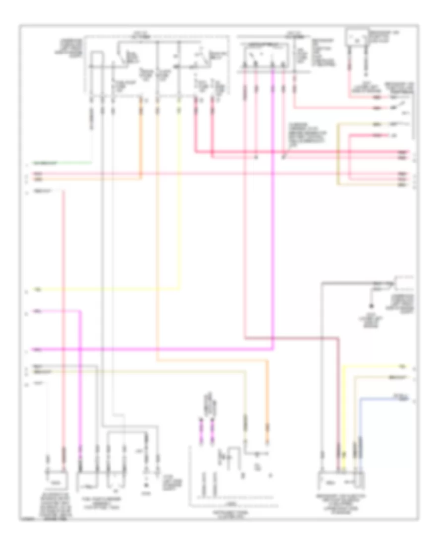
2.9L, Engine Performance Wiring Diagram (1 of 5) for Isuzu i-290 S 2008

List of elements for 2.9L, Engine Performance Wiring Diagram (1 of 5) for Isuzu i-290 S 2008:
- (chassis harness, 39 cm before fuel pump & sender assembly) j310
- 4wd low signal
- 5v reference
- A/c compressor clutch rly ctrl
- A11
- Acc
- Accelerator pedal position (app) sensor (on accelerator bracket)
- Accy volt
- Air conditioning system
- Air solenoid relay ctrl
- Anti-lock brakes system
- App sensor 1 signal
- App sensor 2 signal
- Battery positive voltage
- Body control module (bcm) (behind right kick panel)
- Class 2 serial data
- Cnstr vent fuse 10a
- Computer data lines system
- Cruise control release signal
- Cruise control switch signal
- Cruise control system
- Engine control module (ecm) (right rear of engine compt)
- Evap canister vent sol ctrl
- Fuel level sensor signal
- Fuel pump relay control
- Fuel tank pressure (ftp) sensor (at top left rear of fuel tank)
- Fuel tank pressure sensor signal
- Hot at all times
- Ignition switch
- Ignition voltage
- Low reference
- Mil control
- Off
- Pnk
- Powertrain relay control
- Run
- Start
- Starter enable relay control
- Starting/charging system
- Stop fuse 20a
- Stop lamp control
- Stop lamp switch (above brake pedal assembly)
- Tan
- Transmissions system
- Underhood fuse block (left front side of engine compt)
- Vehicle speed signal
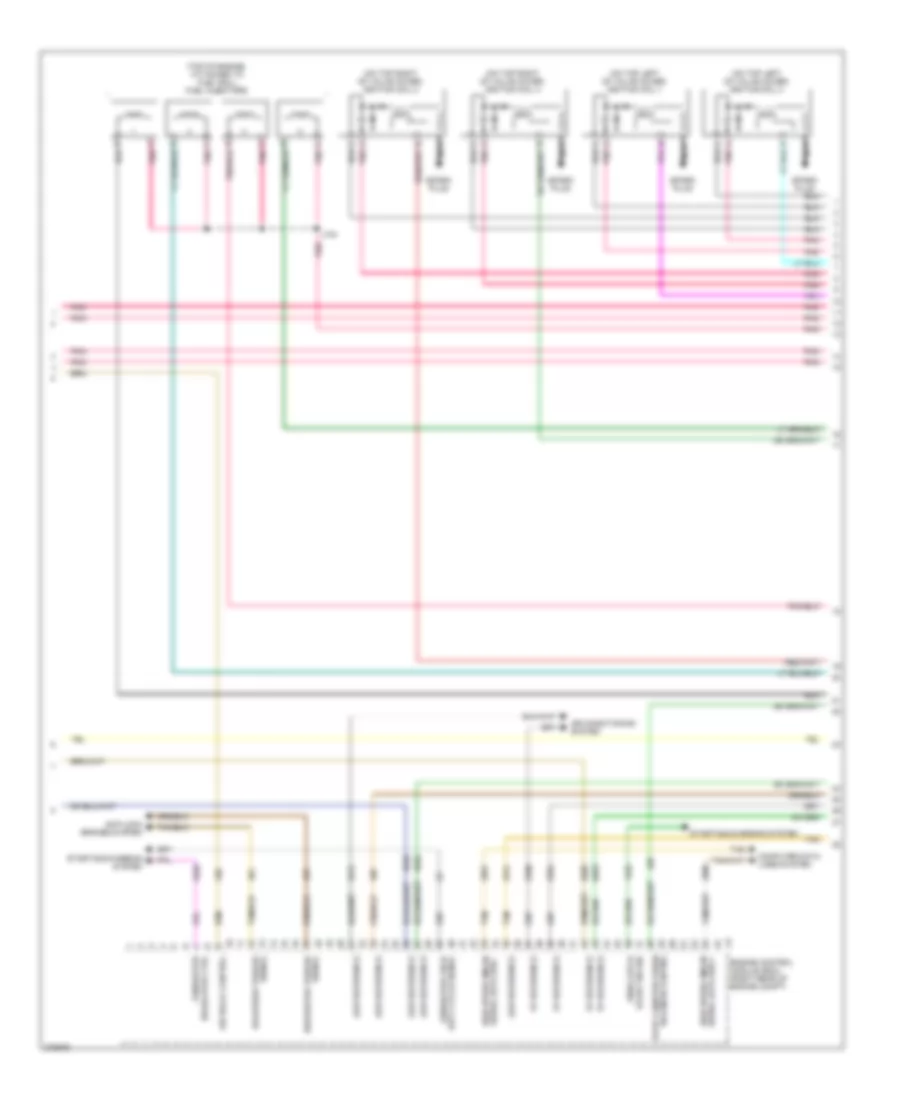
2.9L, Engine Performance Wiring Diagram (2 of 5) for Isuzu i-290 S 2008
List of elements for 2.9L, Engine Performance Wiring Diagram (2 of 5) for Isuzu i-290 S 2008:
- (in engine harness, 24 cm before generator battery control module breakout) j105
- A red
- Air pump fuse 50a
- Air pump relay
- Clstr fuse 10a
- Computer
- Data lines
- Ecm-b fuse 10a
- Etc fuse 15a
- Evaporative emission (evap) canister vent solenoid valve (on side of evap canister, above spare tire)
- F11
- Fuel pump & sender assembly (top of fuel tank)
- Fuel pump relay
- Fuel/pump fuse 15a
- G101 (lower left side of engine)
- G103 (lower left side of engine)
- G105
- Hot at all times
- Ign
- Ind up shift
- Instrument panel cluster (ipc)
- J401
- Jx105 (left side of engine compt)
- Logic
- Mil ind
- Nca
- O2 snsr fuse 15a
- Pnk
- Pnk pnk
- Pwr/trn relay
- Red
- Secondary air injection (air) pump
- Secondary air injection (air) pump fuse block (if equipped)
- Secondary air injection (air) pump relay
- Secondary air injection (air) pump solenoid (if equipped) (upper right side of engine)
- Serial data
- System
- Underhood fuse block (left front side of engine compt)
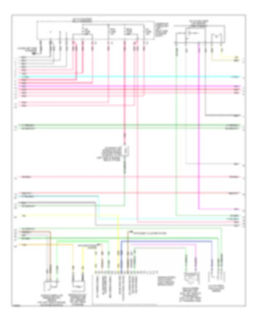
2.9L, Engine Performance Wiring Diagram (3 of 5) for Isuzu i-290 S 2008
List of elements for 2.9L, Engine Performance Wiring Diagram (3 of 5) for Isuzu i-290 S 2008:
- (on top left of valve cover) ignition coil 1
- (on top left of valve cover) ignition coil 3
- (on top right of valve cover) ignition coil 2
- (on top right of valve cover) ignition coil 4
- (top of engine, attached to fuel rail) fuel injectors
- 5v reference
- A pnk
- Air conditioning system
- Air relay control
- Anti-lock brakes system
- Computer data lines system
- Delivered torque
- Duty cycle signal
- Engine control module (ecm) (right rear of engine compt)
- Evap canister purge solenoid control
- Generator
- Generator field
- High speed gmlan
- J104
- Low reference
- Nca
- Pnk
- Pnp/clutch
- Regulator ctrl
- Requested torque
- Serial data bus +
- Serial data bus -
- Signal
- Spark plug
- Start sw sig
- Starting/charging system
- Tan
2.9L, Engine Performance Wiring Diagram (4 of 5) for Isuzu i-290 S 2008
List of elements for 2.9L, Engine Performance Wiring Diagram (4 of 5) for Isuzu i-290 S 2008:
- (lower left side of engine) g103
- (on intake, near map sensor) throttle body
- A/c refrigerant
- Air conditioning system
- Air inj reaction
- Clutch pedal pos sig
- Clutch pedal position (cpp) sensor
- D11
- E11
- Ect sensor signal
- Engine control module (ecm) (right rear of engine compt)
- Engine coolant temperature (ect) sensor (on left rear of engine)
- Erls fuse 15a
- Evaporative emission (evap) canister purge solenoid valve (left side of engine, below intake)
- F11
- Hot w/ run/crnk relay energized
- Ign fuse 15a
- Inj fuse 15a
- Instrument cluster system
- Manifold absolute pressure (map) sensor (top left side of engine, on intake manifold)
- Map sensor signal
- Nca
- Oil press sw sig
- Pcm-i fuse 10a
- Pnk
- Press sens sig
- Tan
- Underhood fuse block (left front side of engine compt)
- Vehicle speed sensor (vss) (2wd: left rear of transmission) (4wd: on left rear of transfer case)
- Vss high signal
- Vss low signal
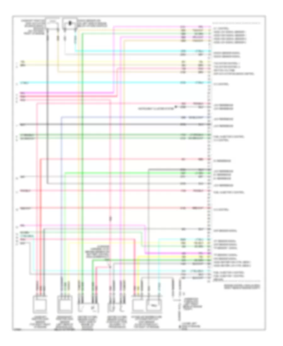
2.9L, Engine Performance Wiring Diagram (5 of 5) for Isuzu i-290 S 2008
List of elements for 2.9L, Engine Performance Wiring Diagram (5 of 5) for Isuzu i-290 S 2008:
- (in engine harness, 24 cm before generator battery control module breakout) j105
- (lower left side of engine) g102
- 5v reference
- A11
- B11
- C11
- Camshaft position (cmp) actuator solenoid bank 1 exhaust (on top right b
- Camshaft position (cmp) sensor (top right front of engine)
- Ckp sensor signal
- Cmp actuator solenoid control
- Cmp sensor signal
- Crankshaft position (ckp) sensor (left rear of engine block, below starter)
- Engine control module (ecm) (right rear of engine compt)
- Front of engine)
- Fuel injector 1 control
- Fuel injector 2 control
- Fuel injector 3 control
- Fuel injector 4 control
- Ground
- Heated oxygen sensor (ho2s) 1 (right side of engine, on exhaust manifold)
- Heated oxygen sensor (ho2s) 2 (in exhaust pipe, adjacent to transmission)
- Ho2s heater high ctrl sens 1
- Ho2s heater low ctrl sens 2
- Ho2s high signal sensor 1
- Ho2s high signal sensor 2
- Ho2s low signal sensor 1
- Ho2s low signal sensor 2
- Iat sensor signal
- Ic 1 control
- Ic 2 control
- Ic 3 control
- Ic 4 control
- Ignition voltage
- Instrument cluster system
- Intake air temperature (iat)/mass air flow (maf) sensor (in air intake duct, top right of engine)
- Knock sensor (ks) (on left side of engine, below intake manifold)
- Knock sensor signal
- Low reference
- Maf sensor signal
- Nca
- Pnk
- Red
- Tac motor control 1
- Tac motor control 2
- Tp sensor 1 signal
- Tp sensor 2 signal
- X2 underhood fuse block (left front x2 side of engine compt)