ENGINE PERFORMANCE
2.6L
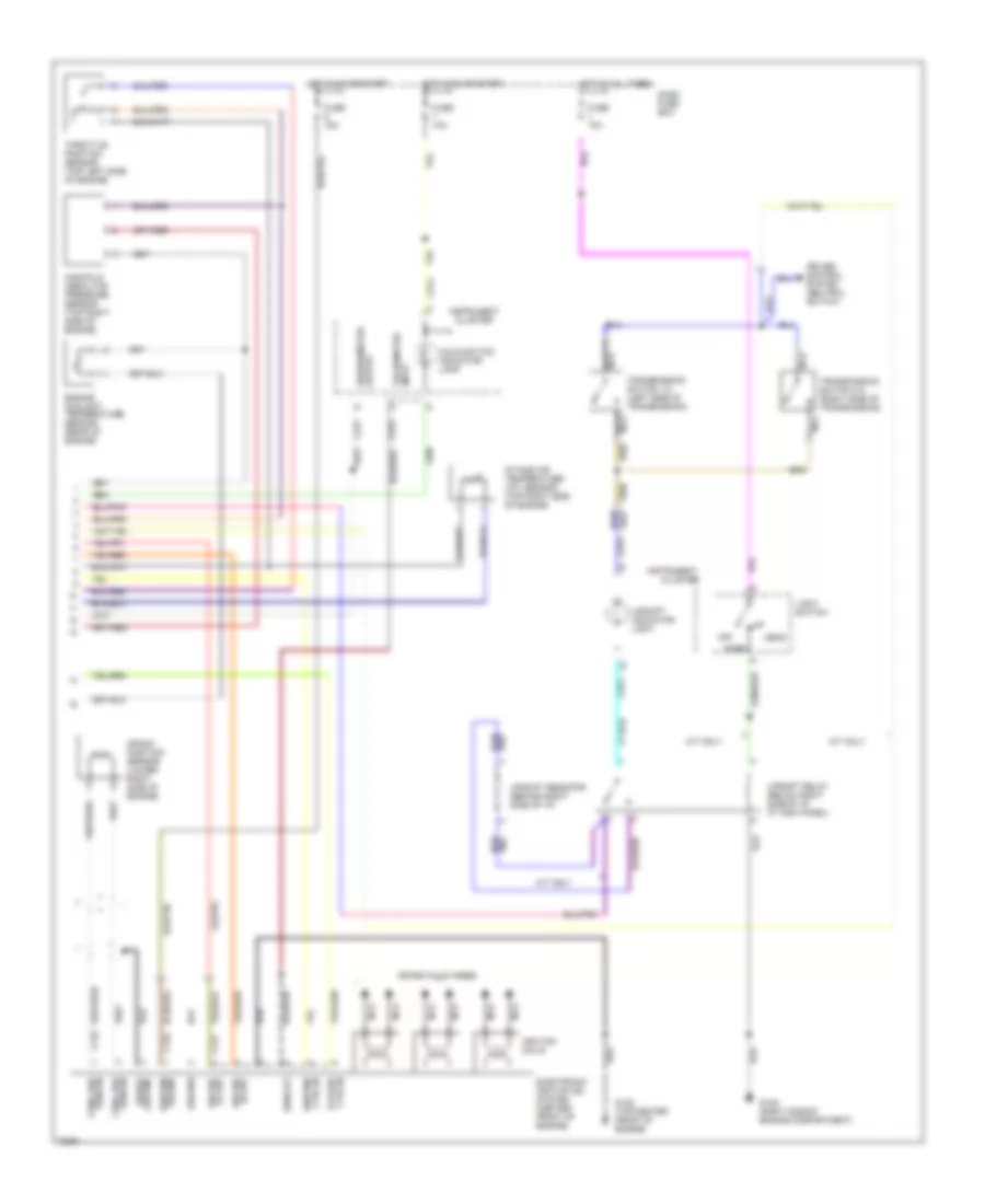
2.6L, Engine Performance Wiring Diagrams (1 of 3) for Isuzu Rodeo S 1995

List of elements for 2.6L, Engine Performance Wiring Diagrams (1 of 3) for Isuzu Rodeo S 1995:
- (at left kick panel)
- (below left side of i/p at kick panel)
- (top of engine)
- A/c-switch
- Air conditioning system
- Air vsv control
- Braided
- C210
- C211
- Connector
- Crank signal
- Crankshaft pos sens
- Dash fuse box
- Data link
- Diagnostic test terminal
- Dlc serial data
- Ect sensor ground
- Ect sensor input
- Egr cut vsv control
- Egr duty sol control
- Engine control module (ecm)
- Engine speed input
- Evap canister vsv ctrl
- Fuel inj #1 control
- Fuel inj #2 control
- Fuel inj #3 control
- Fuel inj #4 control
- Fuel injector #1
- Fuel injector #2
- Fuel injector #3
- Fuel injector #4
- Fuel pres ctrl vsv
- Fuse 11 10a
- Fuse 3 10a
- Fuse 7 10a
- Fuse 8 10a
- G120 (right side of engine)
- Ground
- Ho2s input
- Ho2s shield ground
- Hot at all times
- Hot in on or start
- Hot in start
- Ignition power
- Instrument cluster
- Maf sensor ground
- Maf sensor input
- Maf sensor power
- Mafs shield cround
- Malfunction indicator lamp (mil)
- Map sens grd
- Map sens input
- Map sens ref volt.
- Memory power
- Mil control
- Monitor
- Not
- Red
- Used
- Vehicle speed input
- Wot sw idle position
- Wot sw-wot position
2.6L, Engine Performance Wiring Diagrams (2 of 3) for Isuzu Rodeo S 1995
List of elements for 2.6L, Engine Performance Wiring Diagrams (2 of 3) for Isuzu Rodeo S 1995:
- (left front corner of engine compartment)
- (lower right side of engine)
- (right side of engine compartment)
- (top center of engine)
- Air flow sensor (left front of engine compartment)
- Air management valve (amv)
- Braided
- C274
- California models
- Diode box b
- Engine control module (ecm) relay
- Engine coolant temperature (ect) sensor
- Evaporative emission canister purge vacuum switching valve
- Exhaust gas recirculation (egr) duty solenoid
- Exhaust gas recirculation (egr) vacuum switching valve
- Fuel pressure control valve vacuum switching valve
- Fuse 1 15a
- Fuse/ relay box
- G105 (right side of engine compartment)
- Ground
- Hot at all times
- Idle
- Instrument cluster
- Manifold absolute pressure (map) sensor (right side of engine compartment)
- Not used
- Output
- Power
- Red
- To fuse 2
- Vehicle speed sensor
- Wide open throttle (wot) switch (top center of engine)
- Wot
2.6L, Engine Performance Wiring Diagrams (3 of 3) for Isuzu Rodeo S 1995
List of elements for 2.6L, Engine Performance Wiring Diagrams (3 of 3) for Isuzu Rodeo S 1995:
- (right rear corner oif engine)
- A/c system
- Air regulator (underside of vehicle, right side of engine)
- Braided
- C274
- Charge relay
- Crank position sensor (underside of vehicle, right rear of engine)
- Dash fuse box
- Diode box a
- Distributor assembly
- Distributor cap
- From oil pressure switch
- Fuel pump (underside of vehicle, right front of fuel tank)
- Fuel pump relay
- Fuse 2 20a
- Fuse 5 10a
- Fuse 5 20a
- Fuse 6 10a
- Fuse 9 15a
- Fuse/relay box
- G104 (left rear corner of engine compartment)
- G105 (right side of engine compartment)
- G119 (right front corner of engine)
- G120 (right side of engine)
- G409 (underside of vehicle, behind center of rear bumper)
- Generator (lower left front of engine)
- Ground
- Heated oxygen sensor (ho2s) (lower left side of engine)
- Hot at all times
- Hot in on or start
- Hot in start
- Ignition coil (center rear of engine compartment)
- Indicator control
- Instrument cluster
- Main fuse 1 60a
- Not used
- Power
- Power signal input
- Power switch (underside of vehicle, right side of engine)
- Primary
- Primary winding control
- Radio noise suppressor (center rear of engine compartment)
- Red
- Reference voltage
- Secondary
- Signal output
- Starting/ charging
- System
- Tachometer test connector (not used) (right side of engine compartment)
- Timer core
- To fuse 1
- Voltage regulator
3.2L
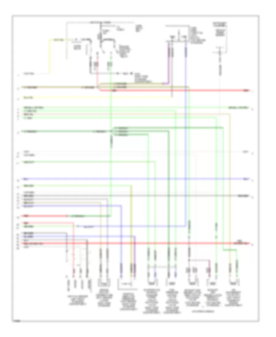
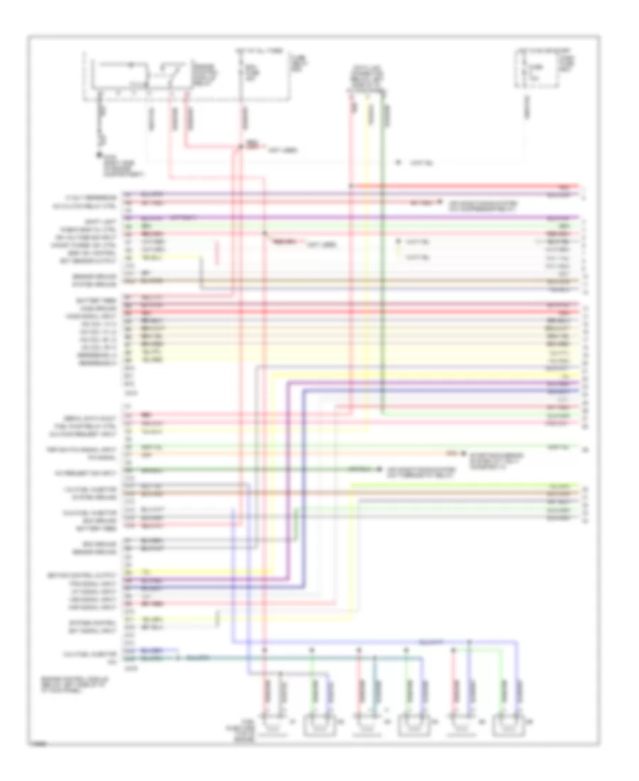
3.2L, Engine Performance Wiring Diagrams (1 of 3) for Isuzu Rodeo S 1995
List of elements for 3.2L, Engine Performance Wiring Diagrams (1 of 3) for Isuzu Rodeo S 1995:
- "check eng" mil ctrl
- (m/t only)
- (not used)
- 1 & 2 fuel injector
- 3 & 4 fuel injector
- 5 & 6 fuel injector
- 5 volt reference
- A/c clutch relay ctrl
- A/c request sig input
- A10
- A11
- A12
- Air conditioning system (a/c compressor relay)
- Air conditioning system (a/c thermostat relay)
- B10
- B11
- B12
- Battery feed
- Bypass control
- C10
- C11
- C12
- C13
- C14
- C15
- C16
- C218
- C219
- Canist purge vsv ctrl
- D10
- D11
- D12
- D13
- D14
- D15
- D16
- Dash fuse box
- Data link connector (below left side of i/p, at kick panel)
- Dlc diag request input
- Ecm fuse 30a
- Ecm ground
- Ect sensor output
- Ect signal input
- Egr vsv control
- Engine control module (below left side of i/p, at kick panel)
- Engine control module relay
- Fuel injectors (top of engine)
- Fuel pump relay ctrl
- Fuse 10a
- Fuse/ relay box
- G105 (right side of engine compartment)
- Ho2s ground
- Ho2s signal input
- Hot at all times
- Hot in on or start
- Iac coil "a" hi
- Iac coil "a" lo
- Iac coil "b" hi
- Iac coil "b" lo
- Iat signal input
- Ign voltage sig input
- Ignition control output
- Map signal input
- N/a
- P/n signal
- Psp switch signal input
- Red
- Reference hi
- Reference lo
- Sensor ground
- Serial data in/out
- Shift light
- Starting/charging system (a/t only) (diode box a)
- System ground
- Tps signal input
- Vss signal input
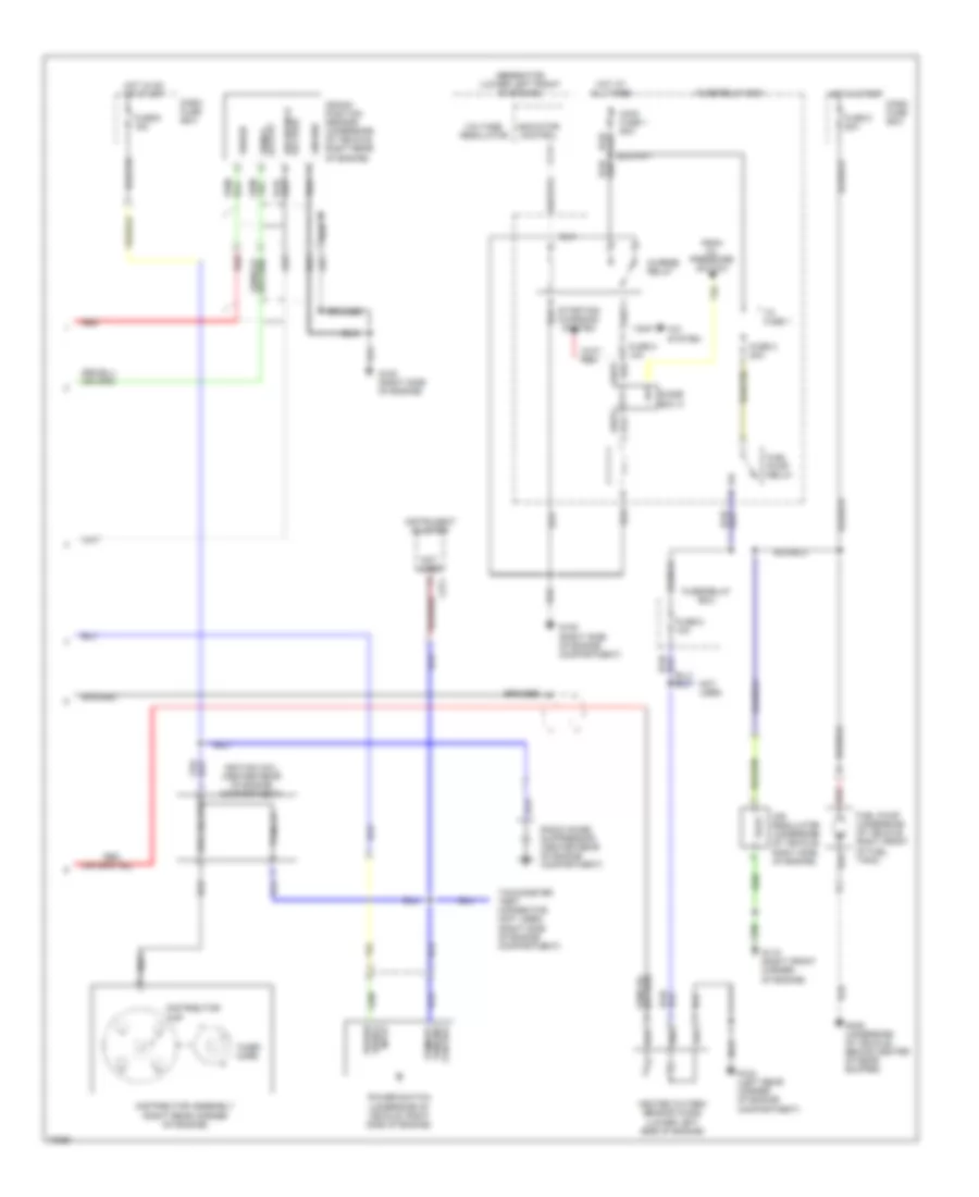
3.2L, Engine Performance Wiring Diagrams (2 of 3) for Isuzu Rodeo S 1995
List of elements for 3.2L, Engine Performance Wiring Diagrams (2 of 3) for Isuzu Rodeo S 1995:
- (a/t)
- (m/t)
- Braided
- C234
- Coolant temp in
- D14
- Data in serial
- Evaporative emission canister purge vacuum switching valve (center rear of engine)
- Exhaust gas recirculation (egr) vacuum switching valve (top center rear of engine)
- Fuel pump (underside of vehicle, right front of fuel tank)
- Fuel pump relay
- Fuse 10a
- Fuse 15a
- Fuse/ relay box
- Fuse/relay box
- G104 (left rear of engine compartment)
- G105 (right side of engine compartment)
- G125 (center front of engine)
- G409 (underside of vehicle, center of rear bumper)
- Ground
- Heated oxygen sensor (underside of vehicle, left side of transmission)
- Hot at all times
- Idle air control valve (top left side of engine)
- Power steering pressure switch (lower left front corner of engine compartment)
- Red
- Tps input
- Transmission control module (tcm) (behind i/p, top of left kick panel)
- W/ a/t
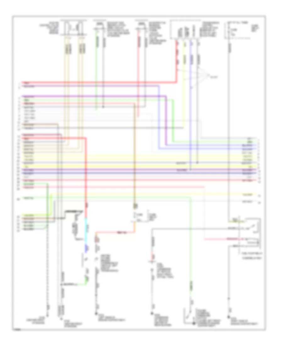
3.2L, Engine Performance Wiring Diagrams (3 of 3) for Isuzu Rodeo S 1995
List of elements for 3.2L, Engine Performance Wiring Diagrams (3 of 3) for Isuzu Rodeo S 1995:
- C176
- C177
- C178
- C274
- C275
- Cluster
- Crank position sensor (lower right side of engine)
- Crnk pos sens in
- Cruise control system (neutral switch)
- Ctrl in bypass
- Ctrl in ignition
- Dash fuse box
- Electronic ignition (ei) system (center front of engine)
- Engine coolant temperature sensor (rear of engine)
- Fuse 10a
- Fuse 15a
- G105 (right side of engine compartment)
- G125 (top center front of engine)
- Ground
- Head
- Hi out ign ref
- Hot at all times
- Hot in on or start
- Ignition coils
- Instrument
- Instrument cluster
- Intake air temperature (iat) sensor (top right side of engine)
- Light switch
- Lo out ign ref
- M/t only
- Malfunction indicator lamp
- Manifold absolute pressure sensor (top right side of engine)
- Nca
- Off
- Output speedometer
- Park
- Power ignition
- Rpm out
- Sens in crnk pos
- Shield ground
- Spark plug wires
- Tachometer input
- Throttle position sensor (top left side of engine)
- Transmission switch 1-2 (left side of transmission)
- Transmission switch 3-4 (right side of transmission)
- Upshift indicator light
- Upshift relay (below right side of i/p, at kick panel)
- Upshift resistor (behind right side of i/p)