ENGINE PERFORMANCE
1.3L
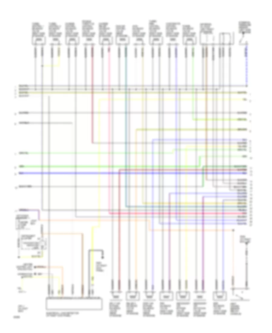
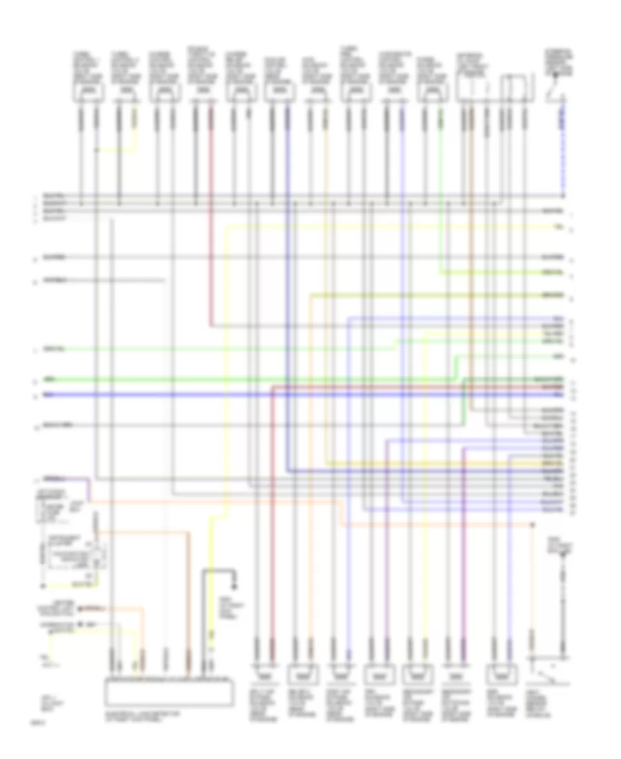
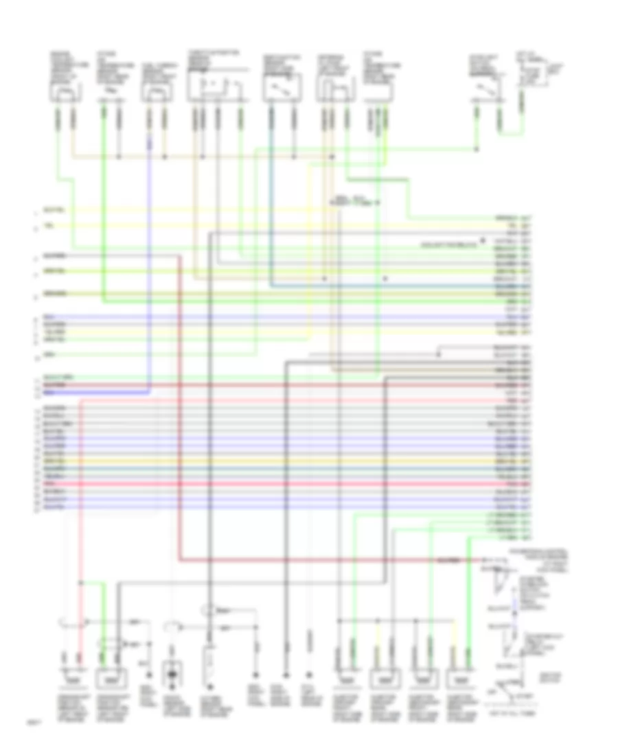
1.3L, Engine Performance Wiring Diagrams, A/T (1 of 3) for Mazda RX-7 1994

List of elements for 1.3L, Engine Performance Wiring Diagrams, A/T (1 of 3) for Mazda RX-7 1994:
- (left rear of
- A/c relay
- Acc
- Air pump relay
- Canada only
- Condenser (left rear of engine compartment)
- Cpu and speedo- meter
- Data link connector (left shock tower)
- Diagnostic module
- Egi fuse 30a
- Egi main relay
- Engine compartment)
- Engine fuse 15a
- Fuel pump (in fuel tank)
- Fuel pump fuse 20a
- Fuel pump relay
- Fuel pump relay (speed)
- Fuel pump resistor (left rear of engine compartment)
- G100 (left front of engine compartment)
- G101 (right front of engine compartment)
- G115 (rear of engine)
- G407 (behind center of rear bumper)
- Hot at all times
- Hot in run or start
- Igniter
- Ignition coil l (rear of engine)
- Ignition coil tf (rear of engine)
- Ignition coil tr (rear of engine)
- Ignition switch
- Instrument cluster
- Joint box
- Main fuse block
- Off
- Powertrain control module (engine) (at right kick panel)
- Powertrain control module (transmission) (at right kick panel)
- Red
- Refrigerant pressure switch
- Relay and fuse block (left front of engine compartment)
- Relay box (right front of engine compartment)
- Room fuse 10a
- Run
- Start
- Vehicle speedometer sensor (on transmission)
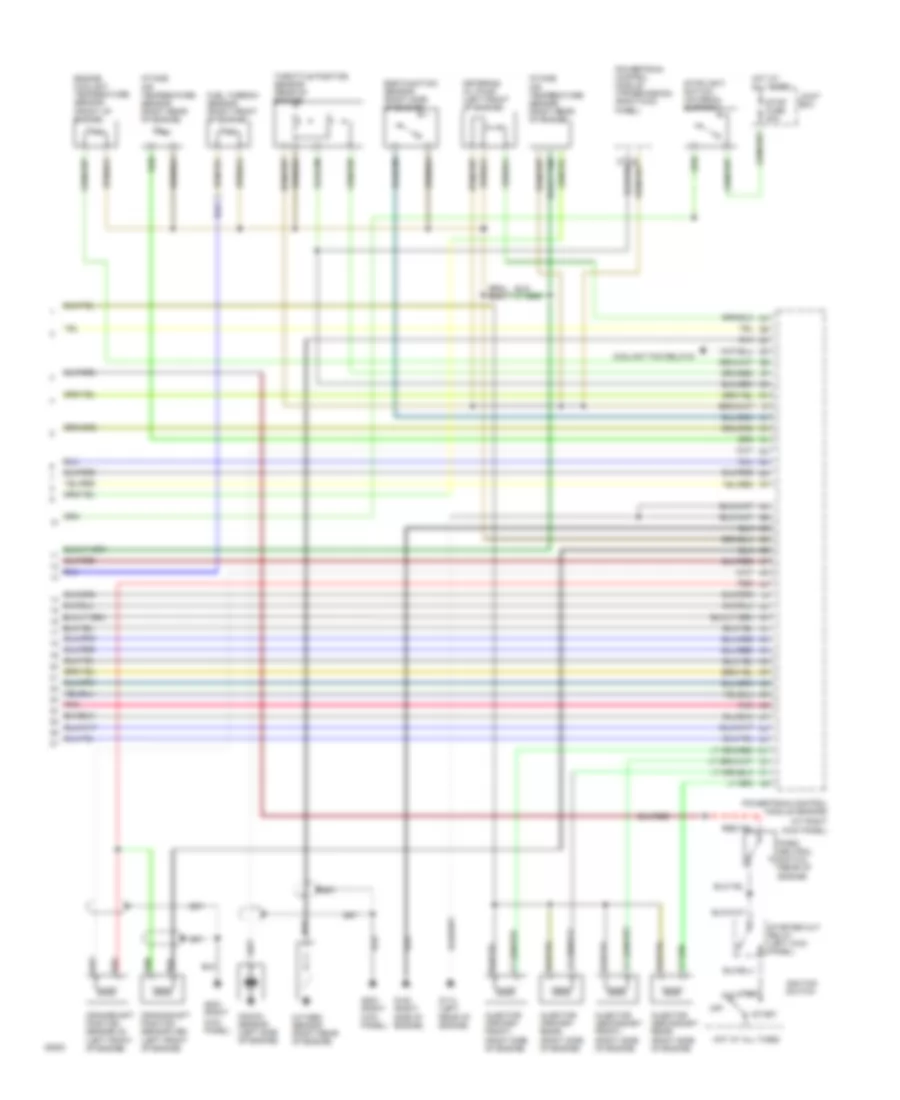
1.3L, Engine Performance Wiring Diagrams, A/T (2 of 3) for Mazda RX-7 1994
List of elements for 1.3L, Engine Performance Wiring Diagrams, A/T (2 of 3) for Mazda RX-7 1994:
- (left side of engine)
- Aws solenoid valve (right side of engine)
- Charge control solenoid valve (right side of engine)
- Charge relief solenoid valve (right side of engine)
- Combination switch
- Cpu 1 (in joint box)
- Double throttle control solenoid valve (right side of engine)
- Egr solenoid valve (right side of engine)
- Electrical load detector (at right kick panel)
- G203 (at right kick panel)
- G305 (at right b-pillar)
- Heat hazard sensor (below console)
- Heater control unit (fan switch)
- Hot in run or start
- Idle air control valve (rear of engine)
- Instrument cluster
- Joint box
- Malfunction indicator lamp
- Meter fuse 15a
- Metering oil pump (left front of engine)
- Pnk
- Port air bypass solenoid valve (rear of engine)
- Prc solenoid valve (right side of engine)
- Purge solenoid valve (right side of engine)
- Relief 2 solenoid valve (rear of engine)
- Secondary air bypass valve (right side of engine)
- Secondary air switching valve (right side of engine)
- Split air bypass solenoid valve (rear of engine)
- Steering pressure sensor
- Turbo control 1 solenoid valve (right side of engine)
- Turbo control 2 solenoid valve (right side of engine)
- Turbo pre- control solenoid valve (right side of engine)
- Wastegate control solenoid valve (right side of engine)
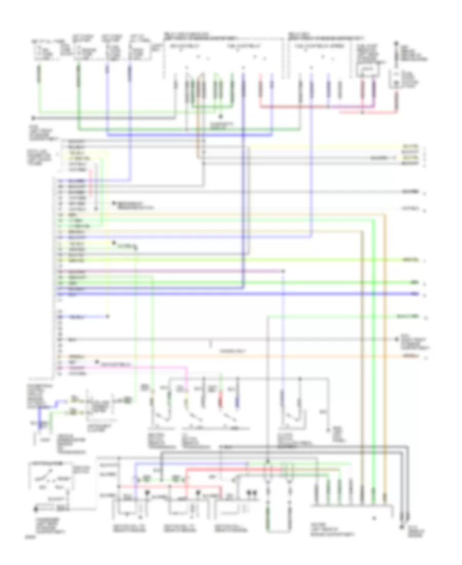
1.3L, Engine Performance Wiring Diagrams, A/T (3 of 3) for Mazda RX-7 1994
List of elements for 1.3L, Engine Performance Wiring Diagrams, A/T (3 of 3) for Mazda RX-7 1994:
- (at right kick panel)
- Acc
- Coolant fan relays
- Crankshaft position sensor (g) (left front of engine)
- Crankshaft position sensor (ne) (left front of engine)
- Egr function sensor (right side of engine)
- Engine coolant temperature sensor (front of engine)
- Fuel thermo- sensor (right front of engine)
- G114 (left
- G120 (right
- G203 (right
- Hot at all times
- Ignition switch
- Injector (primary front) (right side of engine)
- Injector (primary rear) (right side of engine)
- Injector (secondary front) (right side of engine)
- Injector (secondary rear) (right side of engine)
- Intake air temperature sensor (right rear of engine)
- Joint box
- Kick panel)
- Knock sensor (left side of engine)
- Metering oil pump (left front of engine)
- Off
- Oxygen sensor (right rear of engine)
- Panel)
- Park/ neutral switch (rear of engine)
- Pnk
- Powertrain control module (engine)
- Powertrain control module (transmission) (right kick
- Rear of engine)
- Red
- Run
- Side of engine)
- Start
- Starter cut relay (left kick panel)
- Stop fuse 20a
- Stoplight switch (on pedal support)
- Throttle position sensor (rear of engine)
1.3L, Engine Performance Wiring Diagrams, M/T (1 of 3) for Mazda RX-7 1994
List of elements for 1.3L, Engine Performance Wiring Diagrams, M/T (1 of 3) for Mazda RX-7 1994:
- (left rear of
- 1-2 switch (rear of transmission)
- 1st
- 2nd
- A/c relay
- Acc
- Air pump relay
- Canada only
- Clutch switch (on clutch pedal support)
- Condenser (left rear of engine compartment)
- Cpu and speedo- meter
- Data link connector (left shock tower)
- Diagnostic module
- Egi fuse 30a
- Egi main relay
- Engine compartment)
- Engine fuse 15a
- Fuel pump (in fuel tank)
- Fuel pump fuse 20a
- Fuel pump relay
- Fuel pump relay (speed)
- Fuel pump resistor (left rear of engine compartment)
- G100 (left front of engine compartment)
- G101 (right front of engine compartment)
- G115 (rear of engine)
- G200 (left kick panel)
- G407 (behind center of rear bumper)
- Hot at all times
- Hot in run or start
- Igniter
- Ignition coil l (rear of engine)
- Ignition coil tf (rear of engine)
- Ignition coil tr (rear of engine)
- Ignition switch
- Instrument cluster
- Joint box
- Main fuse block
- Neutral switch (rear of transmission)
- Off
- Powertrain control module (engine) (at right kick panel)
- Red
- Refrigerant pressure switch
- Relay and fuse block (left front of engine compartment)
- Relay box (right front of engine compartment)
- Room fuse 10a
- Run
- Start
- Vehicle speedometer sensor (on transmission)
1.3L, Engine Performance Wiring Diagrams, M/T (2 of 3) for Mazda RX-7 1994
List of elements for 1.3L, Engine Performance Wiring Diagrams, M/T (2 of 3) for Mazda RX-7 1994:
- (left side of engine)
- Aws solenoid valve (right side of engine)
- Charge control solenoid valve (right side of engine)
- Charge relief solenoid valve (right side of engine)
- Combination switch
- Cpu 1 (in joint box)
- Double throttle control solenoid valve (right side of engine)
- Egr solenoid valve (right side of engine)
- Electrical load detector (at right kick panel)
- G203 (at right kick panel)
- G305 (at right b-pillar)
- Heat hazard sensor (below console)
- Heater control unit (fan switch)
- Hot in run or start
- Idle air control valve (rear of engine)
- Instrument cluster
- Joint box
- Malfunction indicator lamp
- Meter fuse 15a
- Metering oil pump (left front of engine)
- Pnk
- Port air bypass solenoid valve (rear of engine)
- Prc solenoid valve (right side of engine)
- Purge solenoid valve (right side of engine)
- Relief 2 solenoid valve (rear of engine)
- Secondary air bypass valve (right side of engine)
- Secondary air switching valve (right side of engine)
- Split air bypass solenoid valve (rear of engine)
- Steering pressure sensor
- Turbo control 1 solenoid valve (right side of engine)
- Turbo control 2 solenoid valve (right side of engine)
- Turbo pre- control solenoid valve (right side of engine)
- Wastegate control solenoid valve (right side of engine)
1.3L, Engine Performance Wiring Diagrams, M/T (3 of 3) for Mazda RX-7 1994
List of elements for 1.3L, Engine Performance Wiring Diagrams, M/T (3 of 3) for Mazda RX-7 1994:
- (at right kick panel)
- Acc
- Coolant fan relays
- Crankshaft position sensor (g) (left front of engine)
- Crankshaft position sensor (ne) (left front of engine)
- Egr function sensor (right side of engine)
- Engine coolant temperature sensor (front of engine)
- Fuel thermo- sensor (right front of engine)
- G114 (left
- G120 (right
- G203 (right
- Hot at all times
- Ignition switch
- Injector (primary front) (right side of engine)
- Injector (primary rear) (right side of engine)
- Injector (secondary front) (right side of engine)
- Injector (secondary rear) (right side of engine)
- Intake air temperature sensor (right rear of engine)
- Joint box
- Kick panel)
- Knock sensor (left side of engine)
- Metering oil pump (left front of engine)
- Off
- Oxygen sensor (right rear of engine)
- Pnk
- Powertrain control module (engine)
- Rear of engine)
- Red
- Run
- Side of engine)
- Start
- Starter cut relay (left kick panel)
- Starter interlock switch (on clutch pedal support)
- Stop fuse 20a
- Stoplight switch (on pedal support)
- Throttle position sensor (rear of engine)