ENGINE PERFORMANCE
3.0L
3.0L, Engine Performance Wiring Diagrams (1 of 3) for Mercury Villager Nautica 1996

List of elements for 3.0L, Engine Performance Wiring Diagrams (1 of 3) for Mercury Villager Nautica 1996:
- mil
- (electronic) (analog)
- A/c high pressure switch
- A/c relay
- Achps
- Acr
- Av01
- Av02
- Av03
- Av04
- Av12
- Av20
- Av22
- Av23
- Av28
- Av30
- Av31
- Av32
- Av33
- Av34
- Av36
- Av40
- Av53
- Av56
- Av57
- Av58
- Av61
- Av73
- Avo5
- C272 c268
- Camshaft position (cmp) sensor (top right front
- Ckp
- Ckpref
- Cluster
- Cooling fan relays
- Data link connector (dlc) (left side of engine compartment, near battery)
- Dlc
- Egr temperature (egrt) sensor (on underside of throttle body, air intake)
- Eng cont fuse 10a
- Engine compartment fuse/relay panel
- Engine compartment)
- Engine coolant temperature (ect) sensor (top right rear
- Engine, on throttle body)
- Ep06
- Ep13
- Es39
- Es48
- Fa06
- Fa12
- Ffs
- Fuse 10a
- Fuse 7.5a
- G134 (top of engine)
- Gnd
- Ha41
- Hfan1/hfan2 ry
- Hot at all times
- Hot in start
- Hot in start or run
- Hps
- Hx01
- I/p fuse/ relay panel
- Iat
- Ign
- Ings
- Inj3
- Instrument
- Instrument cluster
- Intake air temperature (iat) sensor (left front corner of
- Isi
- Lo fan ry
- Nca
- Nr01
- Of engine)
- Pcm
- Pcm in
- Pcmr
- Pnk
- Pnps
- Powertrain control module (pcm) (behind top right side of i/p, behind glove box)
- Powertrain control module (pcm) relay (behind right side of i/p)
- Psg
- Psp
- Red
- Res input
- Rpm
- Speed control module
- Speed signal output
- St sig
- Tcm
- Tcm (tp)
- Throttle position (tp) sensor (top left rear of
- Throttle position (tp) switch (top left rear of
- Tp in
- Tp ref
- Tp sw
- Transaxle control module
- Transaxle control module (tcm) (behind top right side of i/p, behind glove box)
- Vss
- W/ electronic cluster
- Wot in
- Zy13
- Zy14
- Zy21
- Zy31
- Zy34
- Zy35
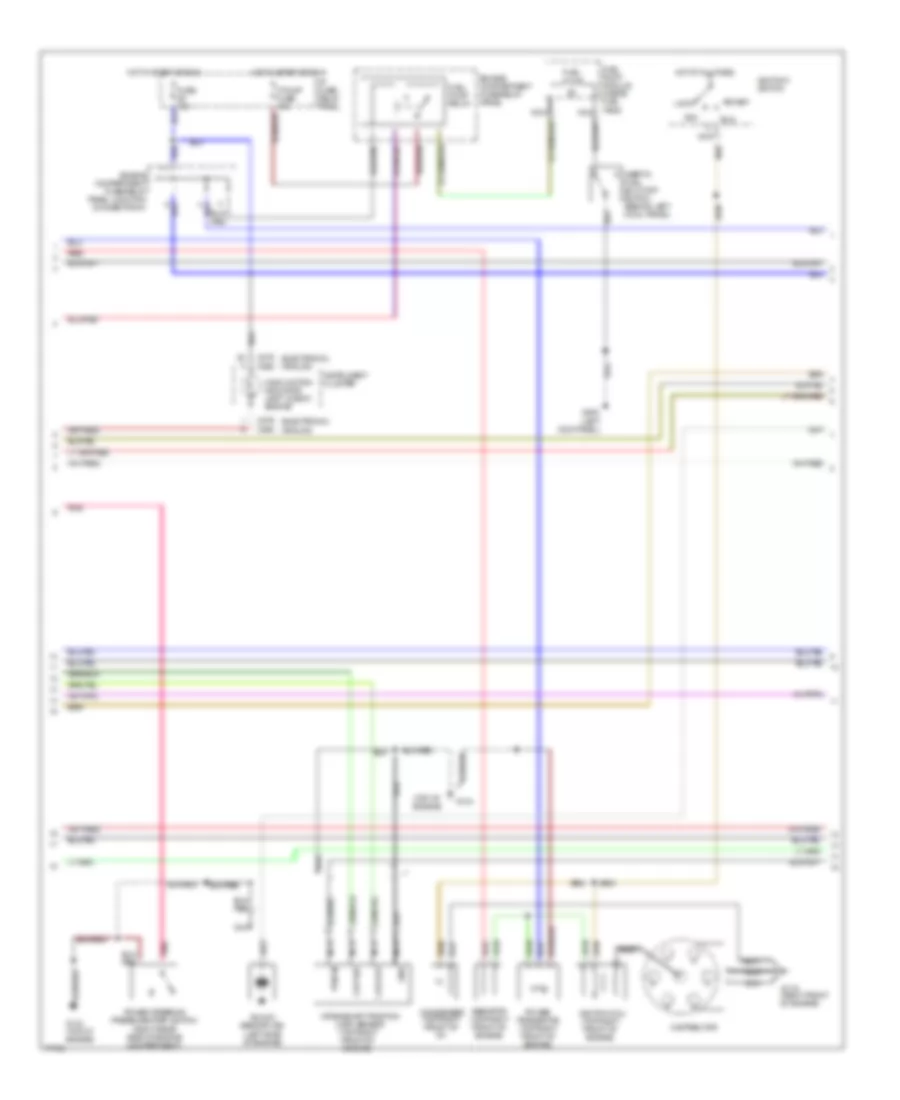
3.0L, Engine Performance Wiring Diagrams (2 of 3) for Mercury Villager Nautica 1996
List of elements for 3.0L, Engine Performance Wiring Diagrams (2 of 3) for Mercury Villager Nautica 1996:
- (analog)
- (electronic)
- (left kick panel)
- (top of engine)
- (top right front of engine)
- Acc
- C268
- C276
- Ckp out
- Ckp ref
- Condenser (top right front of i/p)
- Crankshaft position (ckp) sensor
- Distributor
- Engine compartment fuse/relay panel
- Engine compartment fuse/relay panel junction connector #1
- F pump fuse 15a
- Fuel pump
- Fuel pump module (inside fuel tank)
- Fuel pump relay
- Fuse 10a
- G119 (right front of engine)
- G134
- G134 (top of engine)
- G200
- Gnd
- Hot at all times
- Hot in start or run
- I/p fuse/ relay panel
- Ignitiion switch
- Ignition coil (top right front of engine)
- Inertia fuel shut-off switch (behind left cowl panel)
- Instrument cluster
- Knock sensor (ks) (left side of engine)
- Lock
- Malfunction indicator lamp "check engine"
- Nca
- Pnk
- Power steering pressure (psp) switch (right rear side of engine compartment)
- Power transistor (top right front of engine)
- Pwr in
- Red
- Resistor (top right front of engine)
- Run
- Start
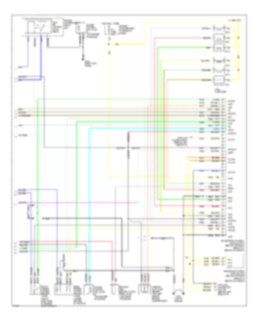
3.0L, Engine Performance Wiring Diagrams (3 of 3) for Mercury Villager Nautica 1996
List of elements for 3.0L, Engine Performance Wiring Diagrams (3 of 3) for Mercury Villager Nautica 1996:
- (behind left side of i/p)
- (front right side of engine compartment)
- (under center of vehicle)
- 1995 vftc c
- Av07
- Av08
- Av09
- Av14
- Av15
- Av16
- Av17
- Av18
- Av19
- Av21
- Av27
- Av37
- Av38
- Av42
- Av46
- Av47
- Av51
- Av52
- Av53
- Av55
- Av59
- Av60
- Av62
- Av63
- Av64
- Av66
- Av99
- Cmp
- Data link connector #1 (behind left side of i/p)
- Data link connector (dlc) #2
- Dlc
- Dlc #1
- Dlc #2
- Ect
- Egrt
- Egrv
- Engine compartment fuse/relay panel
- Engine compartment relay box
- Ep57
- Ep58
- Ep66
- Es90
- Exhaust gas recirculation (egr) valve (left rear of engine)
- Fho2s
- Front heated oxygen sensor (ho2s)
- Fuel injectors
- G134 (top of engine)
- G203 (right kick panel)
- Gnd
- Hot at all times
- Iacv2
- Idle air control (iac) valve #1 (top center of engine)
- Idle air control (iac) valve #2 (top center of engine)
- Idle air control valve relay
- Inj fuse 10a
- Inj1
- Inj2
- Inj3
- Inj4
- Inj5
- Inj6
- Maf+
- Maf-
- Mass air flow (maf) sensor (top left side of engine compartment)
- Nca
- No.1
- No.2
- No.3
- No.4
- No.5
- No.6
- Pcmr in
- Powertrain control module (pcm) (behind top right side of i/p, behind glove box)
- Pwr
- Rear heated oxygen sensor (ho2s)
- Rho2s
- Sig rtn
- Transaxle control module (tcm) (behind top right side of i/p, behind glove box)
- Zy28
- Zy29
- Zy30