ENGINE PERFORMANCE
2.4L
2.4L, Engine Performance Wiring Diagram (1 of 5) for Mitsubishi Galant SE 2010

List of elements for 2.4L, Engine Performance Wiring Diagram (1 of 5) for Mitsubishi Galant SE 2010:
- (attached to pedal support member) stoplight switch
- (left side of engine compt) g12
- (main)
- (near fuel tank, on evaporative emission canister) evaporative emission ventilation solenoid
- (sub)
- (under left side of dash) data link connector
- (upper left end of dash) j/c 1
- A-13
- Accelerator pedal position sensor (above accelerator pedal)
- Air conditioning system
- B-19
- B-20
- B-21
- C-25
- C-29
- C-38
- Computer data lines system
- Cooling fans system
- Cruise control system
- Fuel tank differential pressure sensor (on top of fuel tank)
- Fuse 10a
- Fuse 15a
- Fuse 20a
- G11 (left front of engine compt)
- G13 (left side of engine compt)
- Grounding connector (a-14) (left side of engine compt)
- Hall ic
- Hot at all times
- Knock sensor (on top center of engine, under intake manifold)
- Navigation system
- Nca
- Power steering pressure switch (lower right rear of engine compt)
- Powertrain control module (left front of engine compt)
- Red
- Relay box (left side of engine compt)
- Spare connector (for remote controlled engine starter)
- Starting/charging system
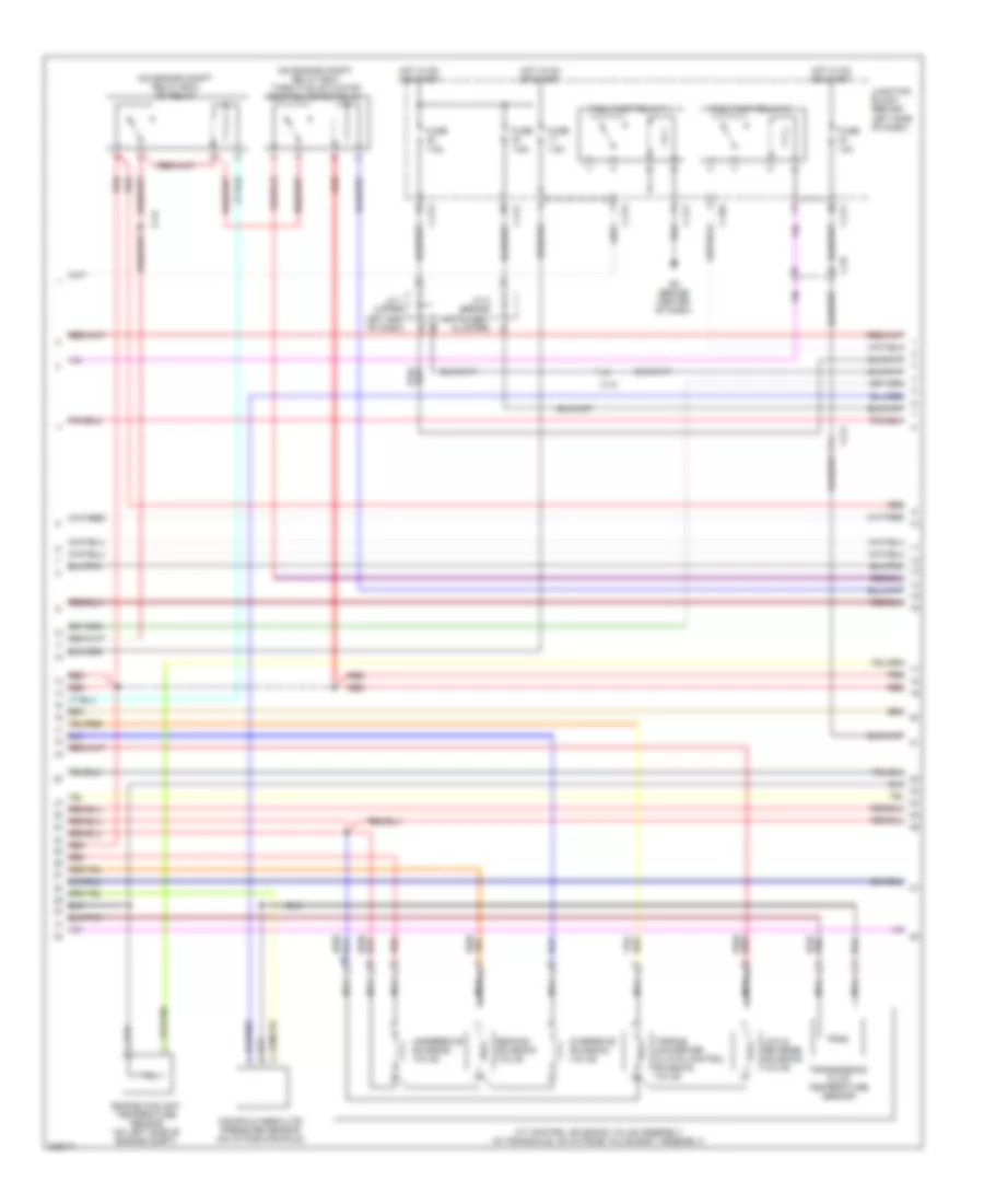
2.4L, Engine Performance Wiring Diagram (2 of 5) for Mitsubishi Galant SE 2010
List of elements for 2.4L, Engine Performance Wiring Diagram (2 of 5) for Mitsubishi Galant SE 2010:
- (on engine compt relay box) mfi relay
- (on engine compt relay box) throttle actuator control motor relay
- A-13
- A/t control solenoid valve assembly (in transaxle, on outside valve body assembly)
- C-204
- C-211
- C-214
- C-29
- Engine coolant temperature sensor (on left side of engine compt)
- Fuel pump relay 1
- Fuel pump relay 2
- Fuse 10a
- Fuse 7.5a
- G5 (behind center of dash)
- Hot in on or start
- J/c 1 (upper left end of dash)
- J/c 2 (behind instrument cluster)
- Junction block (behind left side of dash)
- Low & reverse solenoid valve
- Manifold absolute pressure sensor (on intake manifold)
- Nca
- Overdrive solenoid valve
- Red
- Second solenoid valve
- Torque converter clutch control solenoid valve
- Transmission fluid temperature sensor
- Underdrive solenoid valve
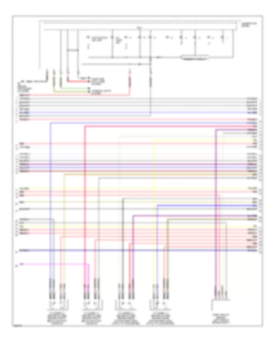
2.4L, Engine Performance Wiring Diagram (3 of 5) for Mitsubishi Galant SE 2010
List of elements for 2.4L, Engine Performance Wiring Diagram (3 of 5) for Mitsubishi Galant SE 2010:
- A/t temp ind
- Combination meter
- Computer data lines system
- Cpu
- Cylinder 1,4 heated oxygen sensor (front) (below exhaust manifold)
- Cylinder 1,4 heated oxygen sensor (rear) (downstream from catalytic converter)
- Cylinder 2,3 heated oxygen sensor (front) (below exhaust manifold)
- Cylinder 2,3 heated oxygen sensor (rear) (downstream from catalytic converter)
- G6 (behind instrument cluster)
- Interior lights system
- Malfunction ind lamp
- Mass airflow sensor (left side of engine compt)
- Nca
- Pnk
- Red
- Rheostat circuit
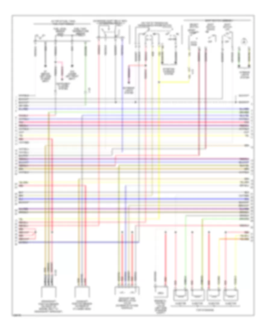
2.4L, Engine Performance Wiring Diagram (4 of 5) for Mitsubishi Galant SE 2010
List of elements for 2.4L, Engine Performance Wiring Diagram (4 of 5) for Mitsubishi Galant SE 2010:
- (in top of fuel tank) fuel pump module
- (on engine compt relay box) a/t control relay
- (on top of transaxle) transmission range switch
- (top of engine)
- A-13
- Auto mode
- B-119
- C-25
- Camshaft position sensor (on rear of cylinder head)
- Crankshaft position sensor (on front of engine, next to crankshaft sprocket)
- Engine oil control valve (left side of engine compt)
- Exhaust gas recirculation valve (on rear of intake manifold)
- Exterior lights system
- Fuel level sensor (main)
- Fuel tank temperature sensor
- G15 (under left front seat)
- G7 (behind left side of rear seat)
- Ill
- Injector
- Instrument cluster system
- Interior lights system
- Nca
- Off
- Pnk
- Red
- Select switch
- Shift switch (down)
- Shift switch (up)
- Shift switch assembly
- Sport mode
- Starting/ charging system
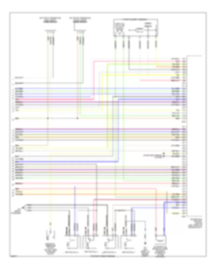
2.4L, Engine Performance Wiring Diagram (5 of 5) for Mitsubishi Galant SE 2010
List of elements for 2.4L, Engine Performance Wiring Diagram (5 of 5) for Mitsubishi Galant SE 2010:
- (main)
- (on top of transaxle) input shaft speed sensor
- (on top of transaxle) output shaft speed sensor
- (sub)
- (top right side of engine)
- B-22
- B-23
- Engine oil pressure switch (on left side of engine block)
- Evaporative emission purge solenoid (on rear of intake manifold)
- G10 (front of engine)
- G11 (left front of engine compt)
- Hall ic
- Ignition coil 1
- Ignition coil 2
- Ignition coil 3
- Ignition coil 4
- Nca
- Pnk
- Powertrain control module (left front of engine compt)
- Red
- Spark plug
- Starting/charging system
- Throttle actuator control motor
- Throttle body assembly