ENGINE PERFORMANCE
1.8L
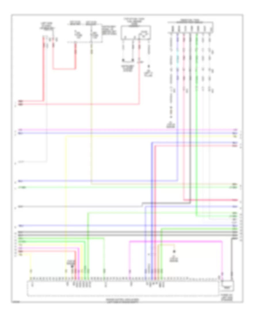
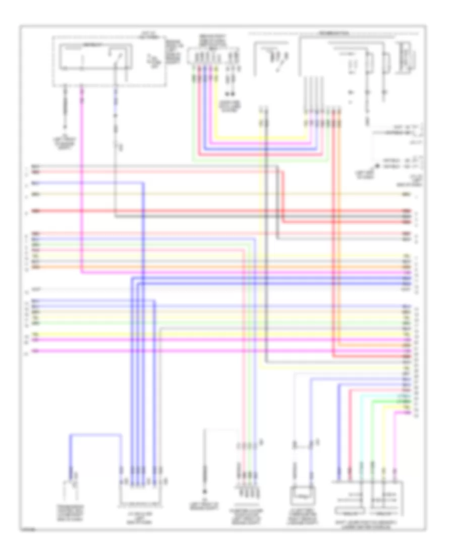
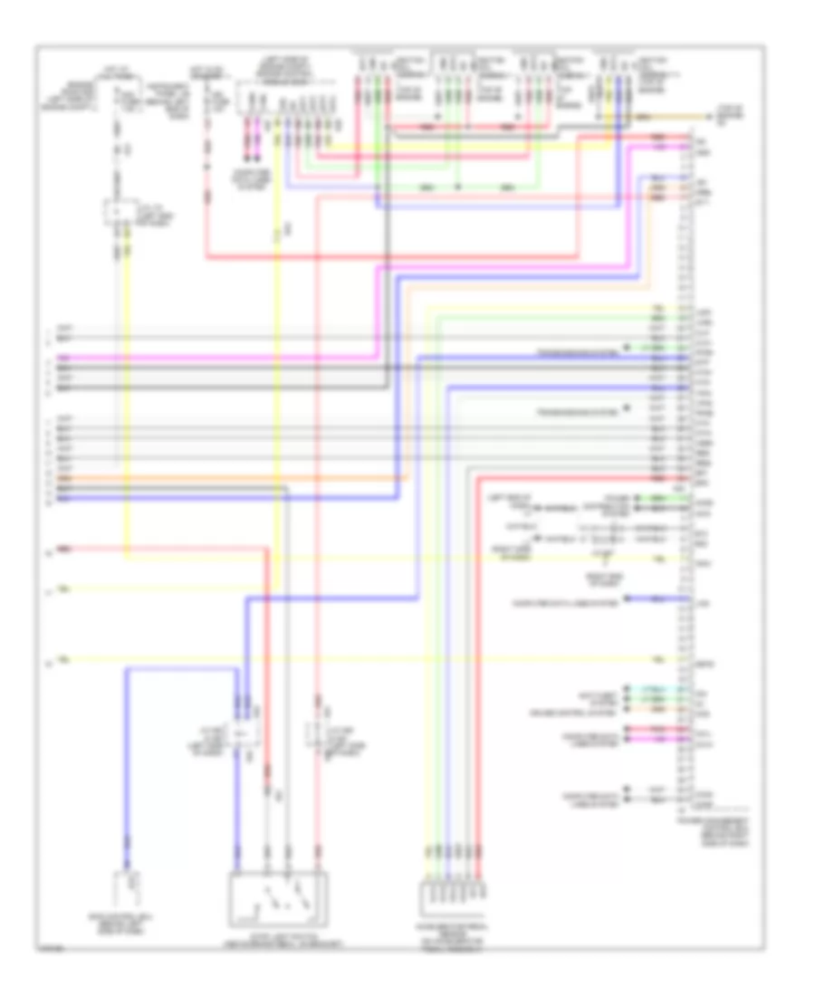
1.8L, Engine Controls Wiring Diagram (1 of 4) for Toyota Prius V 2013

List of elements for 1.8L, Engine Controls Wiring Diagram (1 of 4) for Toyota Prius V 2013:
- (left end of dash) j/c a56
- +b1
- +b2
- +bm
- A3 (left front of engine compt)
- A4 (left front of engine compt)
- A57
- Al1
- Al2
- Batt
- C/opn relay
- Camshaft timing oil control valve (intake) (front of cylinder head)
- Canh
- Canl
- Cann
- Canp
- Computer data line system
- Computer data lines system
- Cooling fans system
- D2 (top of engine)
- Da2
- Eco & ev & power mode switch (combination switch assembly)
- Efi 2 fuse 10a
- Efi main fuse 20a
- Efi main relay
- Egr valve (rear of engine)
- Egr1
- Egr2
- Egr3
- Egr4
- Eng w/p fuse 30a
- Eng w/p relay
- Engine control module (ecm) (left side of engine compt)
- Engine room j/b (left side of engine compt)
- Engine room r/b (left side of engine compt)
- Engine water pump assembly (right front of engine compt)
- Etcs fuse 10a
- Fanh
- Fanl
- Hot at all times
- Ig2 fuse 20a
- Ig2 relay
- Igsw
- J/c a56 (left end of dash)
- J/c l70 (left end of dash)
- J/c l71
- L3 (left end of dash)
- Mpmp
- Mrel
- Nwp
- Pgnd
- Pnk
- Pwms
- Red
- Swp
- Tach
- Vpmp
- Wpi
- Wpo
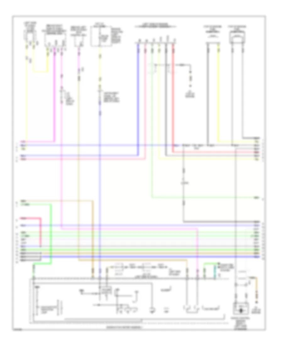
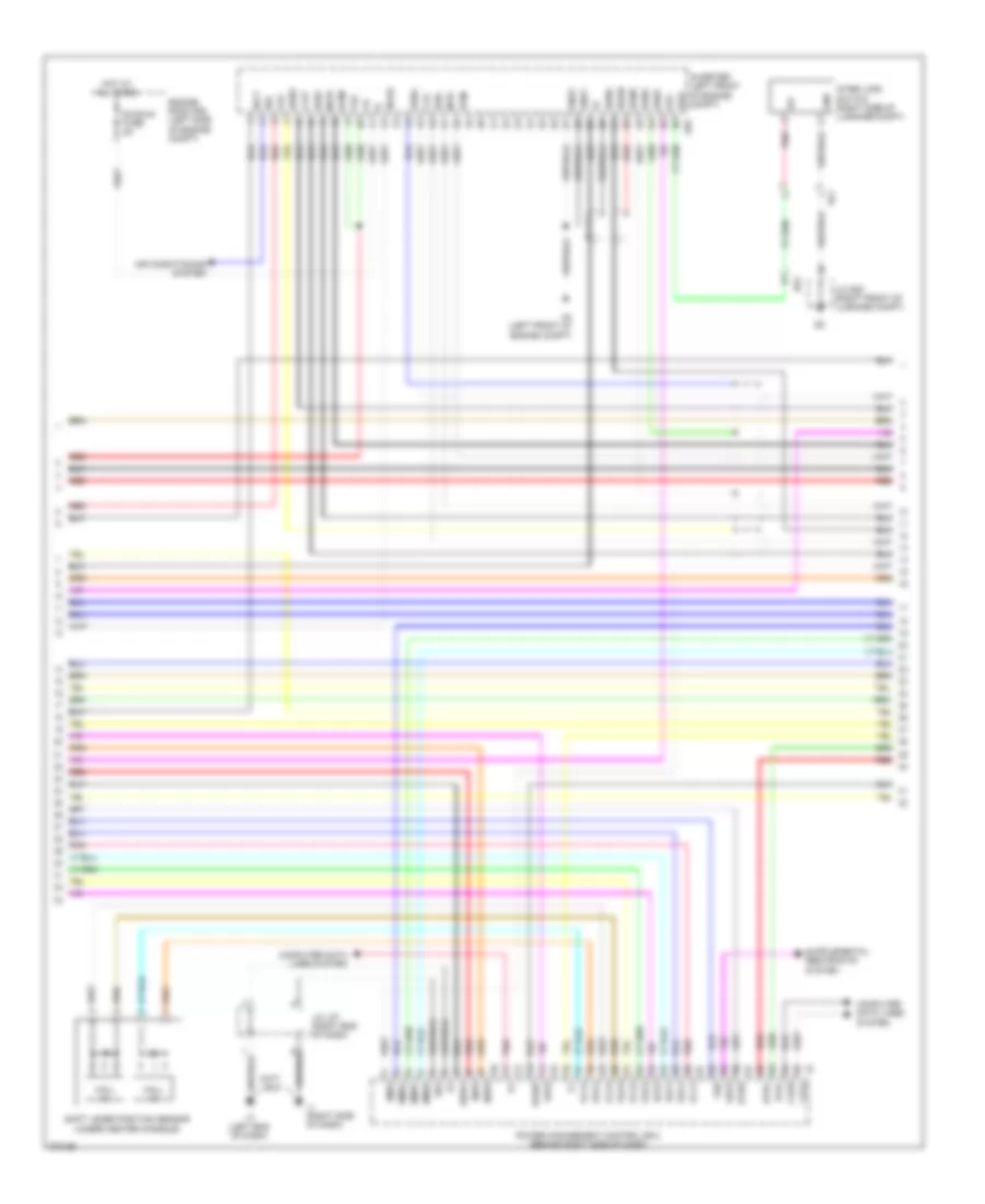
1.8L, Engine Controls Wiring Diagram (2 of 4) for Toyota Prius V 2013
List of elements for 1.8L, Engine Controls Wiring Diagram (2 of 4) for Toyota Prius V 2013:
- (left side of dash) j/c a52 & a53
- (near fuel tank) canister pump module
- (top of engine)
- (top of fuel tank) fuel sender gage assembly
- A44
- A52
- A53
- Ar1
- As1
- C13
- D1 (top of engine)
- D28
- Da1
- E04
- Egr1
- Egr2
- Egr3
- Egr4
- Engine control module (ecm) (left side of engine compt)
- G2o
- Ge01
- Ha1a
- Hot in on or start
- Ht1b
- Igf
- Ign fuse 10a
- Instrument cluster system
- Instrument panel j/b (behind left end of dash)
- Me01
- Met fuse 7.5a
- Mgnd
- Mtrb
- Oc1+
- Oc1-
- Pnk
- Prg
- Pump
- Purge vsv (left side of engine)
- R2 (left "c" pillar)
- Red
- Sgnd
- So1
- Vcc
- Vgnd
- Vlvb
- Vout
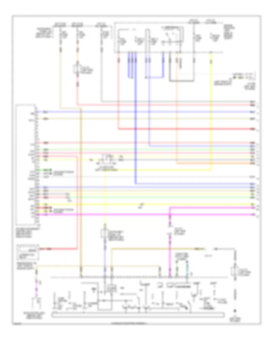
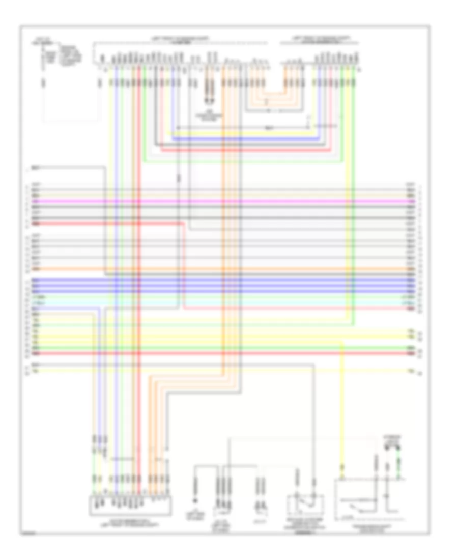
1.8L, Engine Controls Wiring Diagram (3 of 4) for Toyota Prius V 2013
List of elements for 1.8L, Engine Controls Wiring Diagram (3 of 4) for Toyota Prius V 2013:
- (behind left side of dash) skid control ecu
- (behind right side of dash) power management control ecu
- (left side of dash) j/c a52 & a53
- (left side of engine) throttle body assembly
- (top of engine) fuel injector 1
- (top of engine) fuel injector 2
- +5b
- +5v
- A21
- A22
- A37
- A52
- A53
- Al2
- Buzzer
- C18
- Can driver
- Combination meter assembly
- Computer data lines system
- D1 (top of engine)
- Da2
- Df1
- Ecu-b fuse 7.5a
- Engine room r/b (left side of engine compt)
- Hot at all times
- I/f
- Ig2d
- Ign2
- Instrument panel j/b (behind left end of dash)
- J/c l70 (left end of dash)
- J/c l71
- Knock control sensor (bank 1) (left side of engine)
- L27
- L3 (left end of dash)
- Malfunction indicator lamp
- Nca
- Pnk
- Red
- Sp1
- Spdi
- Vta
- Vta2
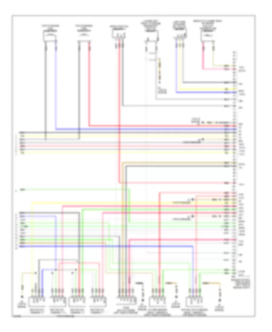
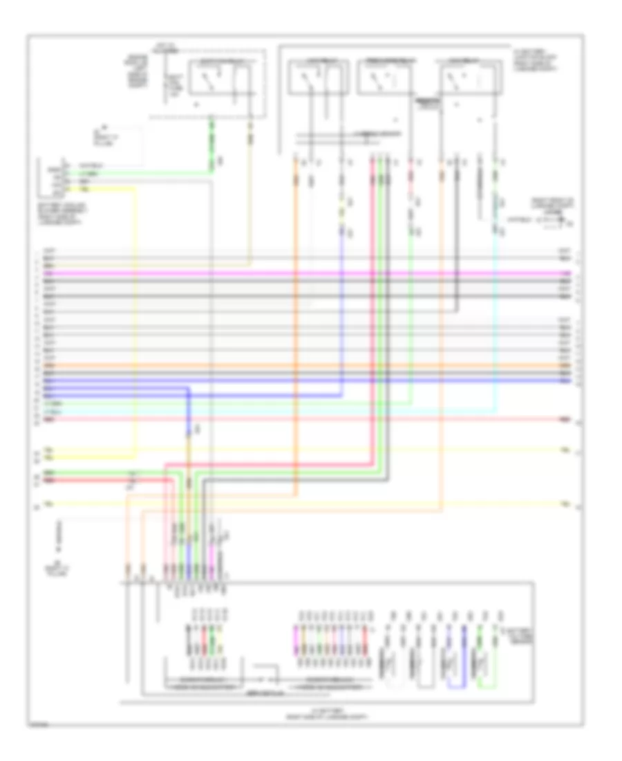
1.8L, Engine Controls Wiring Diagram (4 of 4) for Toyota Prius V 2013
List of elements for 1.8L, Engine Controls Wiring Diagram (4 of 4) for Toyota Prius V 2013:
- (left side of engine) efi vacuum sensor
- (lower left front of engine) crankshaft position sensor
- (rear of cylinder head) efi engine coolant temperature sensor
- (top of engine)
- (top of engine) d1
- (top of engine) fuel injector 3
- (top of engine) fuel injector 4
- A1a+
- A1a-
- Air fuel ratio sensor (bank 1 sensor 1) (top rear of engine)
- Crank position sensor 1
- D1 (top of engine)
- D2 (top of engine)
- D28
- E01
- E02
- E03
- E2g
- Eknk
- Engine control module (ecm) (left side of engine compt)
- Epim
- Eppm
- Eta
- Etha
- Ethw
- G2+
- G2-
- Gnd
- Ha1a
- Ht1b
- Igf
- Ignition coil assembly 1
- Ignition coil assembly 2
- Ignition coil assembly 3
- Ignition coil assembly 4
- Igt1
- Igt2
- Igt3
- Igt4
- Knk1
- Mass air flow meter (left side of engine)
- Nca
- Ne+
- Ne-
- O1b-
- Ox1b
- Oxygen sensor (bank 1 sensor 2) (right rear of engine)
- Pim
- Pnk
- Ppmp
- Red
- Tha
- Thw
- Vcpm
- Vcpp
- Vcta
- Vcv1
- Vta1
- Vta2
- Vvi+
- Vvi-
1.8L, Hybrid System Wiring Diagram (1 of 6) for Toyota Prius V 2013
List of elements for 1.8L, Hybrid System Wiring Diagram (1 of 6) for Toyota Prius V 2013:
- +5b
- +5v
- +b2
- +batt
- A21
- A3 (left front of engine compt)
- A32
- A37
- A44
- A52
- A53
- Air conditioning system
- Al2
- As1
- Bkup
- Buzzer
- C11
- C18
- Can driver
- Charge ind
- Clk
- Combination meter assembly
- Computer data lines system
- Da1
- Ecu-b fuse 7.5a
- Engine room j/b (left side of engine compt)
- Engine room r/b (left side of engine compt)
- Eti
- Ev mode
- Fctl
- G13
- Gmt
- Gmtg
- Hot at all times
- Hot in on or start
- Hv system ind
- I/f
- Igct 2 fuse 10a
- Igct 3 fuse 10a
- Igct fuse 30a
- Igct relay
- Ign fuse 10a
- Ign2
- Ilk
- Instrument panel j/b (behind left end of dash)
- Integration relay
- Ite
- Iwp
- J/c a52 & a53 (left side of dash)
- J/c a56 (left end of dash)
- J/c l70 (left end of dash)
- J/c l71
- L27
- L3 (left end of dash)
- Met fuse 7.5a
- Mmt
- Mmtg
- Niwp
- Nodd
- Over heated hv unit ind
- P lock failure
- Pcu fuse 10a
- Pnk
- Power management control ecu (behind right side of dash)
- Ready
- Red
- Shift by wire p lock failure
- Sio
- Skid control ecu (behind left side of dash)
- Sp1
- Stb
- Stop fuse 10a
- Vlo
1.8L, Hybrid System Wiring Diagram (2 of 6) for Toyota Prius V 2013
List of elements for 1.8L, Hybrid System Wiring Diagram (2 of 6) for Toyota Prius V 2013:
- (behind right side of dash) certification ecu
- +bwp
- A23
- A3 (left front of engine compt)
- A4 (left front of engine compt)
- A54
- A55
- Agnd
- Ag1
- Canh
- Canl
- Code
- Computer data lines system
- Da2
- Engine room j/b (left side of engine compt)
- Gnd
- Hall ic
- Hot at all times
- Hv battery thermometer (right rear of luggage compt)
- Ig2 fuse 20a
- Ig2 relay
- Inverter water pump motor (left front of engine compt)
- J/c a54 & a55 (left end of dash)
- J/c l70 (left end of dash)
- J/c l71
- L3 (left end of dash)
- L62
- Ls1
- Nwp
- Pnk
- Power switch
- Red
- Shift lever position sensor 2 (under center console)
- Ss1
- Ss2
- Swil
- Swp
- Transmission control ecu (lower right end of dash)
- Transponder key coil
- Txct
- Vc5
1.8L, Hybrid System Wiring Diagram (3 of 6) for Toyota Prius V 2013
List of elements for 1.8L, Hybrid System Wiring Diagram (3 of 6) for Toyota Prius V 2013:
- +b2
- A4 (left front of engine compt)
- A59
- Abfs
- Air conditioning system
- Am22
- As1
- Bth+
- Bth-
- Ca2h
- Ca2l
- Clk+
- Clk-
- Computer data lines system
- Dc/dc-s fuse 5a
- Drn1
- Drn2
- Drn3
- Drn4
- Drn5
- Drn8
- E01
- E2x1
- E2x2
- Engine room r/b (left side of engine compt)
- Ethb
- Evsw
- Gnd
- Gnd1
- Gnd2
- Hall ic
- Hot at all times
- Hsdn
- Htm+
- Htm-
- Idh
- Igct
- Ilk
- Ilki
- Ilko
- Inds
- Indw
- Inter lock switch (right side of luggage compt)
- Inverter (left front of engine compt)
- J/c l87 (right end of dash)
- J/c s20 (right front of luggage compt)
- L1 (right side of dash)
- L3 (left end of dash)
- Mth+
- Mth-
- Nodd
- Pnk
- Power management control ecu (behind right side of dash)
- Red
- Req+
- Req-
- Shift lever position sensor (under center console)
- Smrb
- Smrg
- Smrp
- Spdi
- Ssw1
- Sc1
- Thb
- Vcx1
- Vcx2
- Vcx3
- Vcx4
- Vlo
- Vsx1
- Vsx2
- Vsx3
- Vsx4
1.8L, Hybrid System Wiring Diagram (4 of 6) for Toyota Prius V 2013
List of elements for 1.8L, Hybrid System Wiring Diagram (4 of 6) for Toyota Prius V 2013:
- (left front of engine compt) inverter
- (left front of engine compt) motor generator 1
- Acpb
- Acpe
- Air conditioning system
- Amd
- Cbi
- Cei
- D29
- Da1
- Dc/dc fuse 125a
- Drn6
- Eco & ev & power mode switch (combination switch assembly)
- Engine room j/b (left side of engine compt)
- Gcs
- Gcsg
- Gmt
- Gmtg
- Grf
- Grfg
- Gsn
- Gsng
- Hot at all times
- Interior lights system
- J/c l70 (left end of dash)
- J/c l71
- L3 (left end of dash)
- Mcs
- Mcsg
- Mmt
- Mmtg
- Motor generator 2 (left front of engine compt)
- Mrf
- Mrfg
- Mscg
- Msn
- Msng
- Nca
- Red
- Transmission shift main switch
1.8L, Hybrid System Wiring Diagram (5 of 6) for Toyota Prius V 2013
List of elements for 1.8L, Hybrid System Wiring Diagram (5 of 6) for Toyota Prius V 2013:
- (right front of luggage compt) j/c s20
- As1
- Batt fan fuse 10a
- Batt fan relay
- Battery cooling blower assembly (right side of luggage compt)
- Battery voltage sensor
- Bth+
- Bth-
- Busbar module 1
- Busbar module 2
- Current sensor
- Engine room j/b (left side of engine compt)
- Gb0
- Gb1
- Gb2
- Gc0
- Gib
- Gnd
- Gnd0
- Hot at all times
- Hv battery (right side of luggage compt)
- Hv battery junction block (right side of luggage compt)
- Hybrid vehicle battery
- Ig0
- Igct
- Ls1
- Main relay
- Pnk
- Pnk vb4
- Precharge relay
- Red
- Red gb0
- Red vb12
- Resistor
- S1 (right "c" pillar)
- S2 (right "c" pillar)
- Service plug
- Si0
- Sc1
- Tb0
- Tb1
- Tb2
- Tc0
- Thermistor
- Vb2
- Vb5
- Vc1 j1
- Vc10
- Vc11
- Vc12
- Vc13
- Vc14
- Vc2
- Vc3
- Vc4
- Vc5
- Vc6
- Vc7
- Vc8
- Vc9
- Vib
- Vm0
- Z17
1.8L, Hybrid System Wiring Diagram (6 of 6) for Toyota Prius V 2013
List of elements for 1.8L, Hybrid System Wiring Diagram (6 of 6) for Toyota Prius V 2013:
- (left end of dash) l3
- (left side of engine compt) engine control module (ecm)
- (right end of dash)
- (top of engine) d2
- +b1
- A22
- A51
- A52
- A53
- A57
- Accd
- Accelerator pedal sensor (on accelerator pedal assembly)
- Al2
- Am2 fuse 7.5a
- Am21
- Anti-theft system
- Ca1h
- Ca1l
- Ca3n
- Ca3p
- Canh
- Canl
- Ccs
- Clk+
- Clk-
- Computer data lines system
- Cruise control system
- D28
- Da2
- E02
- E12
- Engine room r/b (left side of engine compt)
- Ep1
- Ep2
- G2o
- Gnd
- Hot at all times
- Hot in on or start
- Hsdn
- Htm+
- Htm-
- Ig1d
- Ig2
- Ig2d
- Igf
- Ign fuse 10a
- Ignition coil +b assembly (top of engine)
- Ignition coil assembly (top of engine)
- Ignition coil assembly 4 (top of engine)
- Igt1
- Igt2
- Igt3
- Igt4
- Imi
- Imo
- Instrument panel j/b (behind left end of dash)
- J/c a50 & a51 (left side of dash) a50
- J/c a52 & a53 (left side of dash)
- J/c l70 (left end of dash)
- J/c l87
- L1 (right side of dash)
- Lin2
- Mrel
- Mth+
- Mth-
- Pcon
- Pnk
- Power distribution system
- Power management control ecu (behind right side of dash)
- Ppos
- Red
- Req+
- Req-
- Skid control ecu (behind left side of dash)
- Ssw2
- St1-
- Stop light switch (above brake pedal, on bracket)
- Stp
- Transmissions system
- Vcp1
- Vcp2
- Vpa1
- Vpa2