ENGINE PERFORMANCE
2.5L TURBO
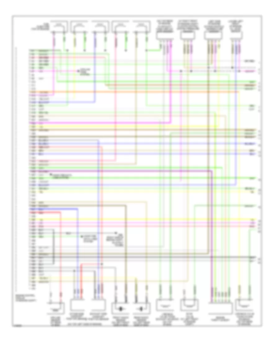
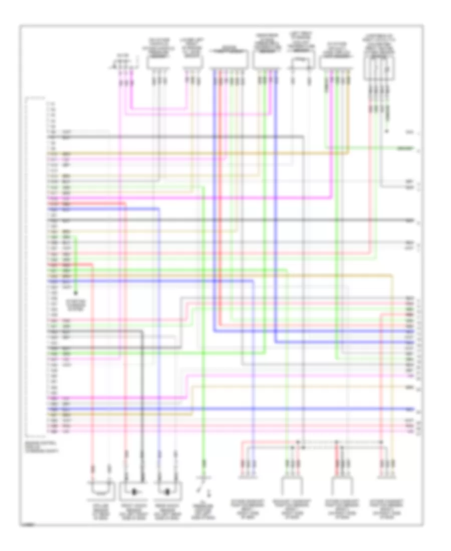
2.5L Turbo, Engine Performance Wiring Diagram, Early Production (1 of 3) for Volvo XC90 2005

List of elements for 2.5L Turbo, Engine Performance Wiring Diagram, Early Production (1 of 3) for Volvo XC90 2005:
- (at right front of engine compt) climate control system pressure sensor
- (left side of engine) intake manifold temperature sensor
- (lower left front of engine) oil level sensor
- (on top left side of engine)
- (on top rear of engine,
- (right side of engine compt, on strut tower)
- A10
- A11
- A12
- A13
- A14
- A15
- A16
- A17
- A18
- A19
- A20
- A21
- A22
- A23
- A24
- A25
- A26
- A27
- A28
- A29
- A30
- A31
- A32
- A33
- A34
- A35
- A36
- A37
- A38
- A39
- A40
- A41
- A42
- A43
- A44
- A45
- A46
- A47
- A48
- A49
- A50
- A51
- A52
- A53
- A54
- A55
- A56
- A57
- A58
- A59
- A60
- A61
- A62
- A63
- A64
- A65
- A66
- A67
- A68
- A69
- A70
- Computer data lines system
- Cooling fans system
- Engine control module (right side of engine compt, forward of strut tower)
- Engine throttle body (left side of engine)
- Evap valve (at left front of engine compt)
- Exhaust side camshaft position sensor
- Front knock sensor (on left front side of engine)
- Fuel injectors (top of engine)
- G96
- Impulse sensor (gasoline)
- In air duct) mass airflow (maf) sensor
- Intake side camshaft position sensor
- Nca
- Pnk
- Rear knock sensor (on left rear side of engine)
- Red
- Variable valve timing exhaust solenoid (on top front of engine)
- Variable valve timing inlet solenoid (at top rear of engine)
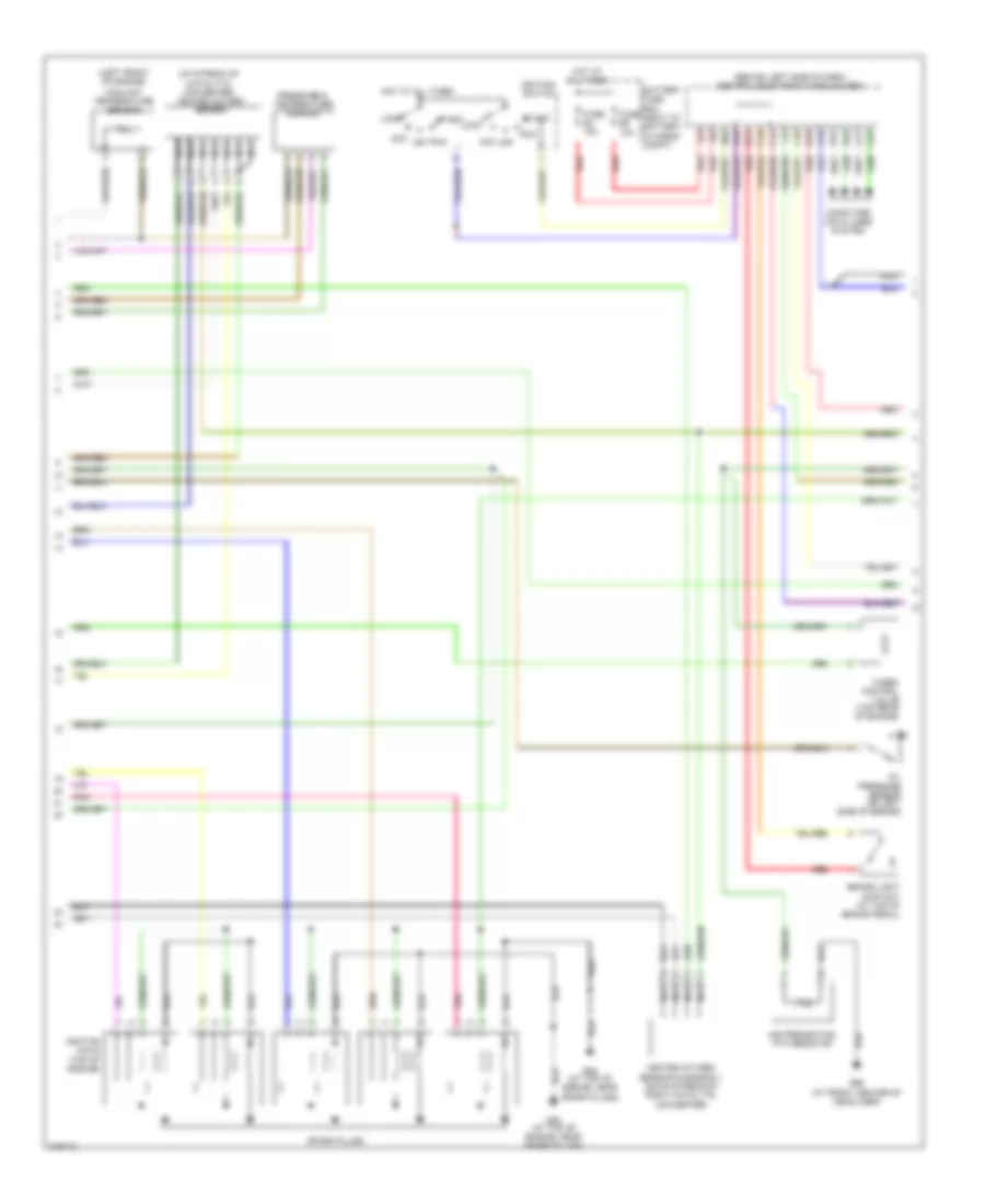
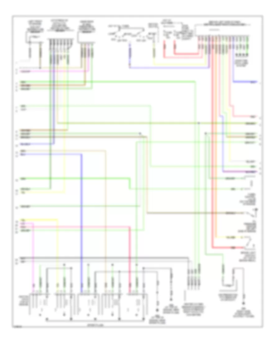
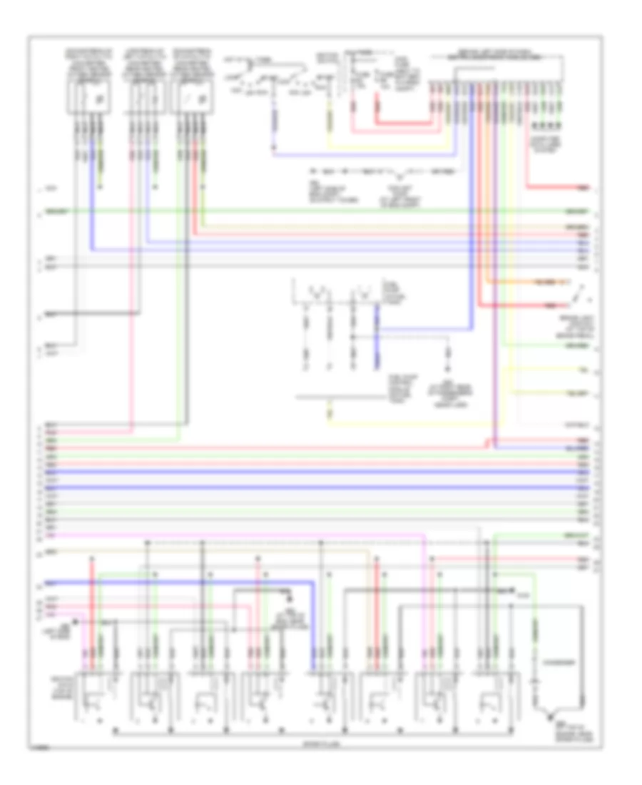
2.5L Turbo, Engine Performance Wiring Diagram, Early Production (2 of 3) for Volvo XC90 2005
List of elements for 2.5L Turbo, Engine Performance Wiring Diagram, Early Production (2 of 3) for Volvo XC90 2005:
- (behind left side of dash) central electronic module (cem)
- (left front of engine)
- (up stream of catalytic converter) heated oxygen sensor
- A16
- Acc
- Air preheating ptc resistor
- B11
- B16
- Battery fuse box (next to battery, in cargo compt)
- Brake light contact (at top of brake pedal)
- C14
- C21
- C22
- C34
- C35
- Computer data lines system
- Coolant temperature sensor
- D16
- D34
- D49
- D60
- Fuse e4 15a
- Fuse e5 10a
- G88 (at top of engine, near spark plugs)
- G89 (at top of engine, near spark plugs)
- G96 (at front center of headliner)
- Heated oxygen sensor diagnosis 1 (down stream of right catalytic converter)
- Hot at all times
- Ignition coils (top of engine)
- Ignition switch
- Lock
- Nca
- Off
- Oil pressure sensor (on left side of engine)
- Pnk
- Pressure & temperature sensor
- Red
- Run
- Spark plugs
- Start
- Turbo control valve (top rear of engine)
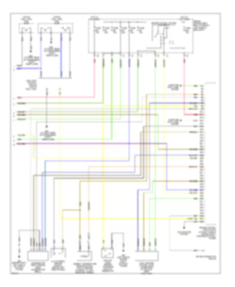
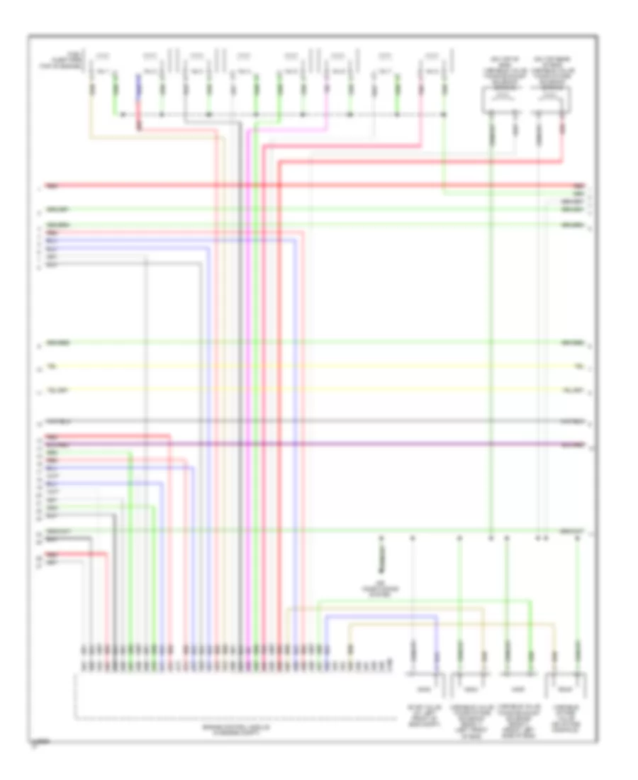
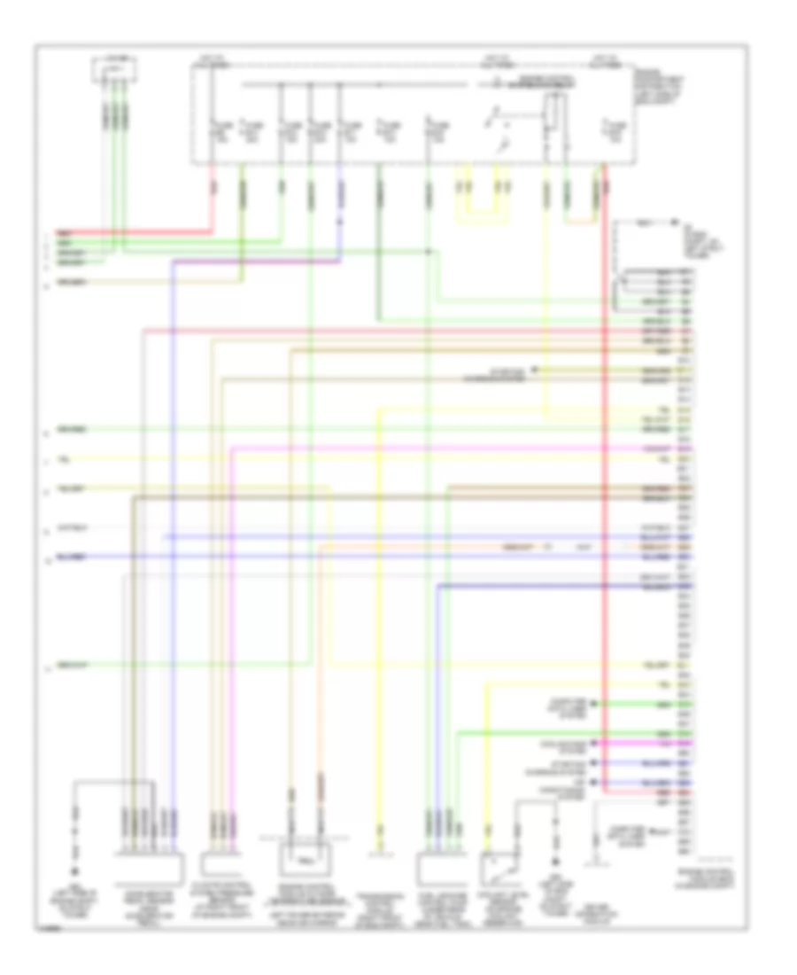
2.5L Turbo, Engine Performance Wiring Diagram, Early Production (3 of 3) for Volvo XC90 2005
List of elements for 2.5L Turbo, Engine Performance Wiring Diagram, Early Production (3 of 3) for Volvo XC90 2005:
- (top of fuel tank) fuel pump
- (v70r)
- Accelerator pedal sensor (near accelerator pedal)
- Ambient temperature engine control module sensor (integral to left rearview mirror)
- B10
- B11
- B12
- B13
- B14
- B15
- B16
- B17
- B18
- B19
- B20
- B21
- B22
- B23
- B24
- B25
- B26
- B27
- B28
- B29
- B30
- B31
- B32
- B33
- B34
- B35
- B36
- B37
- B38
- B39
- B40
- B41
- B42
- B43
- B44
- B45
- B46
- B47
- B48
- Clutch pedal sensor (manual) (behind left side of dash)
- Computer data lines system
- Coolant level sensor (on engine coolant reservoir)
- Cooling fans system
- Driver information module
- Engine compartment relay/fuse box (left side of eng compt)
- Engine control module (ecm) (at right side of engine compt, forward of strut tower)
- Engine control system main relay
- Fuel leakage control pump (under rear of vehicle, near fuel tank)
- Fuel pump control module (top of fuel tank)
- Fuse b11 20a
- Fuse b21 15a
- Fuse b23 10a
- Fuse b4 20a
- Fuse b5 15a
- Fuse b6 15a
- Fuse b8 10a
- G48 (at right rear of passenger's compt, near floor)
- G93 (engine compt, left side of on strut tower)
- G93 (left side of engine compt, on strut tower)
- Hot at all times
- Nca
- Red
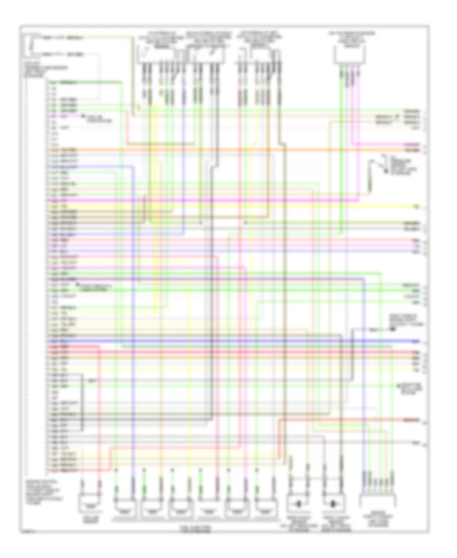
2.5L Turbo, Engine Performance Wiring Diagram, Late Production (1 of 3) for Volvo XC90 2005
List of elements for 2.5L Turbo, Engine Performance Wiring Diagram, Late Production (1 of 3) for Volvo XC90 2005:
- (at right front of engine compt) climate control system pressure sensor
- (left side of engine) intake manifold temperature sensor
- (lower left front of engine) oil level sensor
- (on top left side of engine)
- (on top rear of engine,
- (right side of engine compt, on strut tower)
- A10
- A11
- A12
- A13
- A14
- A15
- A16
- A17
- A18
- A19
- A20
- A21
- A22
- A23
- A24
- A25
- A26
- A27
- A28
- A29
- A30
- A31
- A32
- A33
- A34
- A35
- A36
- A37
- A38
- A39
- A40
- A41
- A42
- A43
- A44
- A45
- A46
- A47
- A48
- A49
- A50
- A51
- A52
- A53
- A54
- A55
- A56
- A57
- A58
- A59
- A60
- A61
- A62
- A63
- A64
- A65
- A66
- A67
- A68
- A69
- A70
- Computer data lines system
- Cooling fans system
- Engine control module (in engine compt)
- Engine throttle body
- Evap valve (at left front of engine compt)
- Exhaust side camshaft position sensor
- Front knock sensor (on left front side of eng)
- Fuel injectors (top of engine)
- G96
- Impulse sensor (at rear of eng)
- In air duct) mass airflow (maf) sensor
- Intake side camshaft position sensor
- Nca
- Pnk
- Rear knock sensor (on left rear side of eng)
- Red
- Variable valve timing exhaust solenoid (on top of eng)
- Variable valve timing intake solenoid (on top rear of engine)
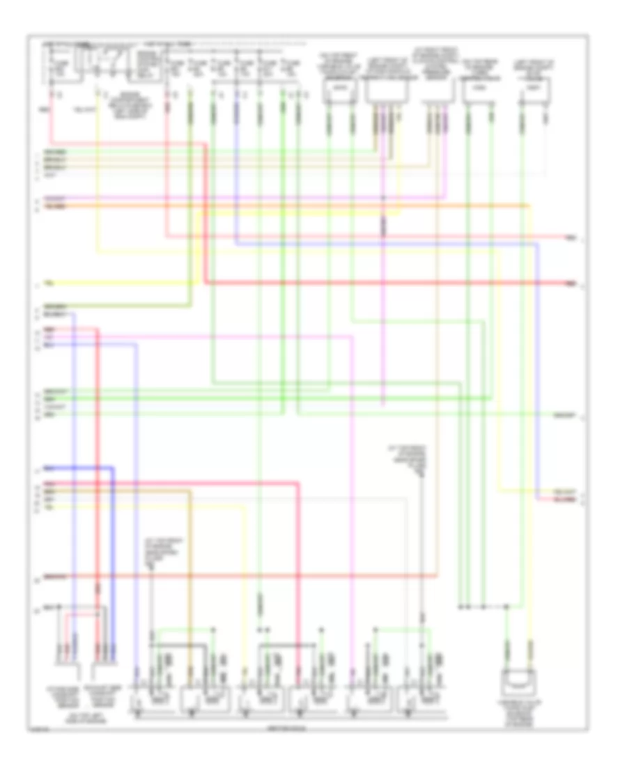
2.5L Turbo, Engine Performance Wiring Diagram, Late Production (2 of 3) for Volvo XC90 2005
List of elements for 2.5L Turbo, Engine Performance Wiring Diagram, Late Production (2 of 3) for Volvo XC90 2005:
- (behind left side of dash) central electronic module (cem)
- (left front of engine)
- (near rear of eng) pressure & temperature sensor
- (up stream of catalytic converter) heated oxygen sensor
- A16
- Acc
- Air preheating ptc resistor (in air duct)
- B11
- B16
- Brake light contact (at top of brake pedal)
- C14
- C21
- C22
- C34
- C35
- Computer data lines system
- Coolant temperature sensor
- D16
- D34
- D49
- D60
- Fuse e4 15a
- Fuse e5 10a
- G88 (at top of engine, near spark plugs)
- G89 (at top of engine, near spark plugs)
- G96 (right side of eng compt, on strut tower)
- Heated oxygen sensor diagnosis 1 (down stream of right catalytic converter)
- Hot at all times
- Ignition coils (top of engine)
- Ignition switch
- Lock
- Main fuse (next to battery, in cargo compt)
- Nca
- Off
- Oil pressure monitor (on left side of engine)
- Pnk
- Red
- Run
- Spark plugs
- Start
- Turbo control valve (on top rear of engine)
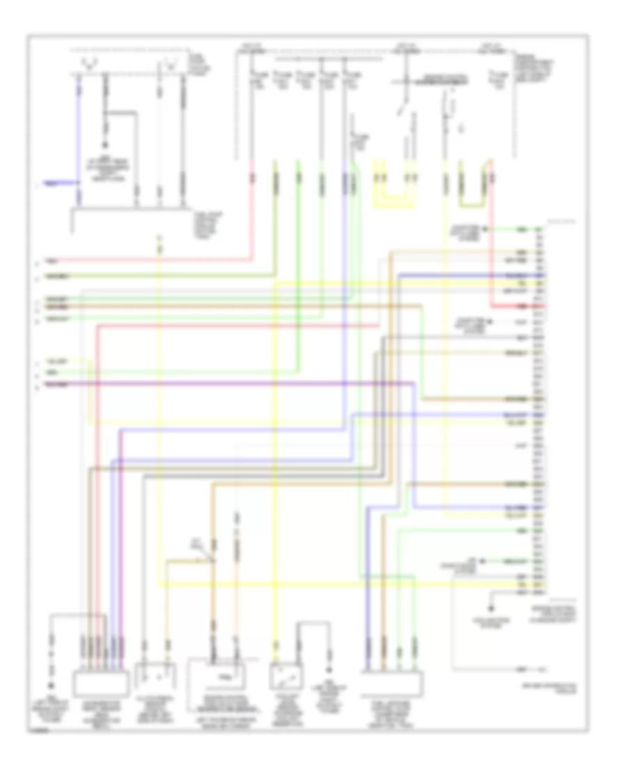
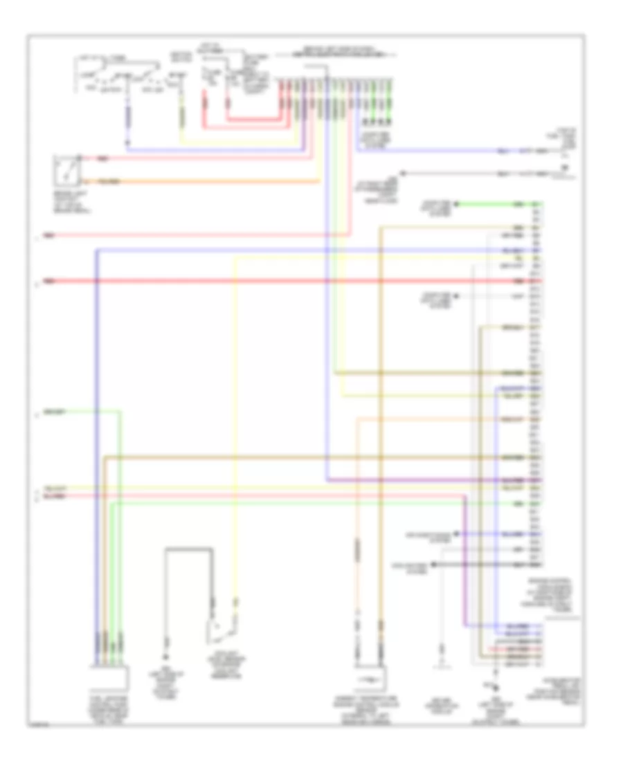
2.5L Turbo, Engine Performance Wiring Diagram, Late Production (3 of 3) for Volvo XC90 2005
List of elements for 2.5L Turbo, Engine Performance Wiring Diagram, Late Production (3 of 3) for Volvo XC90 2005:
- Accelerator pedal sensor (near accelerator pedal)
- Air conditioning system
- B10
- B11
- B12
- B13
- B14
- B15
- B16
- B17
- B18
- B19
- B20
- B21
- B22
- B23
- B24
- B25
- B26
- B27
- B28
- B29
- B30
- B31
- B32
- B33
- B34
- B35
- B36
- B37
- B38
- B39
- B40
- B41
- B42
- B43
- B44
- B45
- B46
- B47
- B48
- Clutch pedal sensor (manual) (behind left side of dash)
- Computer data lines system
- Coolant level sensor (on engine coolant reservoir)
- Cooling fans system
- Driver information module
- Engine compartment distribution (left side of eng compt)
- Engine control module (ecm) (in engine compt)
- Engine control module outside temperature sensor
- Engine control system main relay
- Fuel leakage control pump (under rear of vehicle, near fuel tank)
- Fuel pump (in fuel tank)
- Fuel pump control module (on fuel tank)
- Fuse b10 20a
- Fuse b11 10a
- Fuse b12 15a
- Fuse b14 20a
- Fuse b15 15a
- Fuse b19 10a
- Fuse b9 15a
- G48 (at right rear of passenger's compt, near floor)
- G93 (left side of engine compt, on strut tower)
- Hot at all times
- Left power exterior rearview mirror
- M/t only
- Nca
- Red
2.9L TURBO
2.9L Turbo, Engine Performance Wiring Diagram (1 of 3) for Volvo XC90 2005
List of elements for 2.9L Turbo, Engine Performance Wiring Diagram (1 of 3) for Volvo XC90 2005:
- (down stream of right catalytic converter) heated oxygen sensor (diagnosis 1)
- (on top rear of engine in air duct) mass airflow sensor
- (right side of engine compt, on strut tower) g96
- (up stream of catalytic converter) heated oxygen sensor
- (up stream of left catalytic converter) heated oxygen sensor 3
- A10
- A11
- A12
- A13
- A14
- A15
- A16
- A17
- A18
- A19
- A20
- A21
- A22
- A23
- A24
- A25
- A26
- A27
- A28
- A29
- A30
- A31
- A32
- A33
- A34
- A35
- A36
- A37
- A38
- A39
- A40
- A41
- A42
- A43
- A44
- A45
- A46
- A47
- A48
- A49
- A50
- A51
- A52
- A53
- A54
- A55
- A56
- A57
- A58
- A59
- A60
- A61
- A62
- A63
- A64
- A65
- A66
- A67
- A68
- A69
- A70
- Computer data lines system
- Coolant temperature sensor (left front of engine)
- Cooling fans system
- Engine control module (ecm) (at right side of engine compt, forward of strut tower)
- Engine throttle body (left side of engine)
- Front knock sensor (on left front side of engine)
- Fuel injectors (top of engine)
- Impulse sensor
- Nca
- Oil pressure sensor (on left side of engine)
- Pnk
- Rear knock sensor (on left rear side of engine)
- Red
2.9L Turbo, Engine Performance Wiring Diagram (2 of 3) for Volvo XC90 2005
List of elements for 2.9L Turbo, Engine Performance Wiring Diagram (2 of 3) for Volvo XC90 2005:
- (at right front of engine compt) climate control system pressure sensor
- (at top front of engine, near spark plugs)
- (at top front of engine, near spark plugs) g88
- (left front of engine compt) evap valve
- (left front of engine compt) intake manifold temperature sensor
- (on top front of engine) variable valve timing outlet solenoid
- (on top left side of engine)
- (on top rear of engine) turbo control valve
- Engine compartment relay/fuse box (left side of eng compt)
- Engine control system main relay
- Exhaust side camshaft position sensor
- Fuse b11 20a
- Fuse b21 15a
- Fuse b23 10a
- Fuse b4 20a
- Fuse b5 10a
- Fuse b6 15a
- Fuse b8 10a
- G89
- Hot at all times
- Ignition coils
- Intake side camshaft position sensor
- Pnk
- Red
- Variable valve timing inlet solenoid (top rear of engine)
2.9L Turbo, Engine Performance Wiring Diagram (3 of 3) for Volvo XC90 2005
List of elements for 2.9L Turbo, Engine Performance Wiring Diagram (3 of 3) for Volvo XC90 2005:
- (behind left side of dash) central electronic module (cem)
- (top of fuel tank) fuel pump
- A16
- Acc
- Accelerator pedal (ap) position sensor (near accelerator pedal)
- Air conditioning system
- Ambient temperature engine control module sensor (integral to left rearview mirror)
- B10
- B11
- B12
- B13
- B14
- B15
- B16
- B17
- B18
- B19
- B20
- B21
- B22
- B23
- B24
- B25
- B26
- B27
- B28
- B29
- B30
- B31
- B32
- B33
- B34
- B35
- B36
- B37
- B38
- B39
- B40
- B41
- B42
- B43
- B44
- B45
- B46
- B47
- B48
- Battery fuse box (next to battery, in cargo compt)
- Brake light contact (at top of brake pedal)
- C14
- C21
- C22
- C34
- C35
- Computer data lines system
- Coolant level sensor (on engine coolant reservoir)
- Cooling fans system
- D16
- D34
- D49
- D60
- Driver information module
- Engine control module (ecm) (at right side of engine compt, forward of strut tower)
- Fuel leakage control pump (under rear of vehicle, near fuel tank)
- Fuse e4 15a
- Fuse e5 10a
- G48 (at right rear of passenger's compt, near floor)
- G93 (left side of engine compt, on strut tower)
- Hot at all times
- Ignition switch
- Lock
- Nca
- Off
- Red
- Run
- Start
4.4L
4.4L, Engine Performance Wiring Diagram (1 of 4) for Volvo XC90 2005
List of elements for 4.4L, Engine Performance Wiring Diagram (1 of 4) for Volvo XC90 2005:
- (in intake air duct) mass airflow (maf) sensor
- (left front of engine)
- (lower left front of engine) oil level sensor
- (near rear of eng) pressure & temperature sensor
- (on intake manifold) intake manifold pressure sensor
- (upstream of right catalytic converter) front heated oxygen sensor (bank 2)
- 54/129
- A10
- A11
- A12
- A13
- A14
- A15
- A16
- A17
- A18
- A19
- A20
- A21
- A22
- A23
- A24
- A25
- A26
- A27
- A28
- A29
- A30
- A31
- A32
- A33
- A34
- A35
- A36
- A37
- A38
- A39
- A40
- A41
- A42
- A43
- A44
- A45
- A46
- A47
- A48
- A49
- A50
- A51
- A52
- A53
- A54
- A55
- A56
- A57
- A58
- A59
- A60
- Coolant temperature sensor
- Engine control module (in engine compt)
- Engine throttle body
- Exhaust camshaft position sensor, bank 1 (right side of eng)
- Front knock sensor (on left front side of eng)
- Impulse sensor (at rear of eng)
- Intake camshaft position sensor, bank 1 (right side of eng)
- Intake camshaft position sensor, bank 2 (on right side of eng)
- Nca
- Oil pressure monitor (on left side of eng)
- Pnk
- Rear knock sensor (on left rear side of eng)
- Red
- Starting/ charging system
4.4L, Engine Performance Wiring Diagram (2 of 4) for Volvo XC90 2005
List of elements for 4.4L, Engine Performance Wiring Diagram (2 of 4) for Volvo XC90 2005:
- (behind left side of dash) central electronic module (cem)
- (downstream of catalytic converter) rear heated oxygen sensor (bank 1)
- (downstream of right catalytic converter) front heated oxygen sensor (bank 1)
- (upstream of left catalytic converter) rear heated oxygen sensor (bank 2)
- A16
- Acc
- All times
- B11
- B14
- B16
- Brake light contact (at top of brake pedal)
- C14
- C15
- C21
- C22
- C34
- C35
- Computer data lines system
- Condenser
- Coolant pump (at left front of eng compt)
- D16
- D34
- D49
- D60
- Fuel pump (in fuel tank)
- Fuel pump control module (on fuel tank)
- Fuse e4 15a
- Fuse e5 10a
- G100
- G48 (at right rear of passenger's compt, near floor)
- G88 (at top of eng, near spark plugs)
- G89 (at top of engine, near spark plugs)
- G90 (left side of eng)
- G93 (left side of eng compt, on strut tower)
- Hot at all times
- Ignition coils (top of engine)
- Ignition switch
- Lock
- Main fuse (next to battery, in cargo compt)
- Nca
- Off
- Pnk
- Red
- Run
- Spark plugs
- Start
4.4L, Engine Performance Wiring Diagram (3 of 4) for Volvo XC90 2005
List of elements for 4.4L, Engine Performance Wiring Diagram (3 of 4) for Volvo XC90 2005:
- (on top of eng) variable valve timing exhaust solenoid (bank 2)
- (on top rear of eng) variable valve timing intake solenoid (bank 2)
- A100
- A61
- A62
- A63
- A64
- A65
- A66
- A67
- A68
- A69
- A70
- A71
- A72
- A73
- A74
- A75
- A76
- A77
- A78
- A79
- A80
- A81
- A82
- A83
- A84
- A85
- A86
- A87
- A88
- A89
- A90
- A91
- A92
- A93
- A94
- A95
- A96
- A97
- A98
- A99
- Air conditioning system
- Engine control module (in engine compt)
- Evap valve (at left front of eng compt)
- Fuel injectors (top of engine)
- Inj 1
- Inj 2
- Inj 3
- Inj 4
- Inj 5
- Inj 6
- Inj 7
- Inj 8
- Pnk
- Red
- Variable intake valve (on intake manifold)
- Variable valve timing exhaust solenoid (bank 1) (front left side of eng)
- Variable valve timing intake solenoid (bank 1) (left front of eng)
4.4L, Engine Performance Wiring Diagram (4 of 4) for Volvo XC90 2005
List of elements for 4.4L, Engine Performance Wiring Diagram (4 of 4) for Volvo XC90 2005:
- 54/129
- Accelerator pedal sensor (near accelerator pedal)
- Air conditioning system
- B10
- B11
- B12
- B13
- B14
- B15
- B16
- B17
- B18
- B19
- B20
- B21
- B22
- B23
- B24
- B25
- B26
- B27
- B28
- B29
- B30
- B31
- B32
- B33
- B34
- B35
- B36
- B37
- B38
- B39
- B40
- B41
- B42
- B43
- B44
- B45
- B46
- B47
- B48
- B49
- B50
- B51
- B52
- B53
- B54
- B55
- B56
- B57
- B58
- B59
- B60
- Climate control system pressure sensor (at right front of engine compt)
- Computer data lines system
- Coolant level sensor (on engine coolant reservoir)
- Cooling fans system
- Driver information module
- Engine compartment distribution (left side of eng compt)
- Engine control module (ecm) (in engine compt)
- Engine control module outside temperature sensor
- Engine control system main relay
- Fuel leakage control pump (under rear of vehicle, near fuel tank)
- Fuse b10 20a
- Fuse b11 10a
- Fuse b12 15a
- Fuse b13 10a
- Fuse b14 20a
- Fuse b15 15a
- Fuse b19 10a
- Fuse b9 15a
- G2 (in eng compt, on left strut tower)
- G93 (left side of eng compt, on strut tower)
- G93 (left side of engine compt, on strut tower)
- Hot at all times
- Left power exterior rearview mirror
- Nca
- Red
- Starting/ charging system
- Transmission control module (right front of eng compt)