SUPPLEMENTAL RESTRAINTS
Supplemental Restraint Wiring Diagram for Dodge Neon High Line 1995
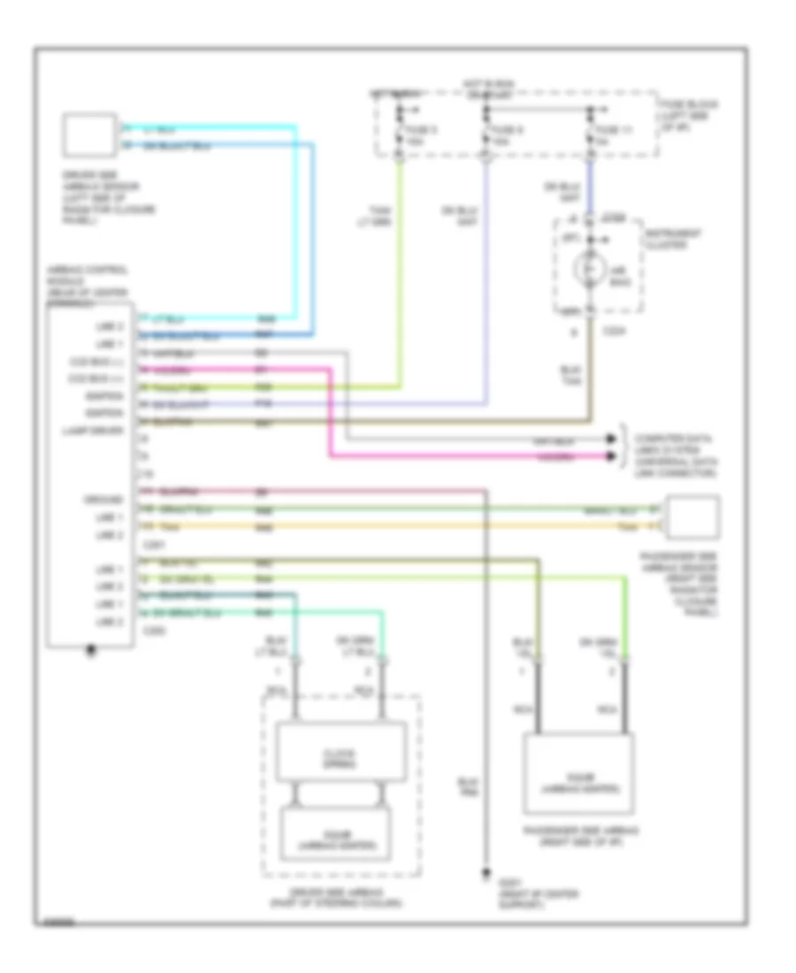
List of elements for Supplemental Restraint Wiring Diagram for Dodge Neon High Line 1995:
- (rt)
- Air bag
- Airbag control module (rear of center console)
- C201
- C202
- C224
- Ccd bus (+)
- Ccd bus (-)
- Clock spring
- Computer data lines system (universal data link connector)
- Driver side airbag (part of steering coulmn)
- Driver side airbag sensor (left side of radiator closure panel)
- F15
- F25
- Fuse 11 5a
- Fuse 5 10a
- Fuse 9 10a
- Fuse block (left side of i/p)
- G201 (right i/p center support)
- Ground
- Hot in run
- Hot in run or start
- Ignition
- Instrument cluster
- Lamp driver
- Line 1
- Line 2
- Nca
- Passenger side airbag (right side of i/p)
- Passenger side airbag sensor (right side radiator closure panel)
- R41
- R42
- R43
- R44
- R45
- R46
- R47
- R48
- R49
- Squib (airbag igniter)
- Tan
 Čeština
 Dansk
Dansk Deutsch
 Ελληνικά
 English
 English
 Suomi
Suomi Français
 Français
 עברית
עברית Hrvatski
 Magyar
 Italiano
 日本語
日本語 한국어
한국어 Nederlands
 Polski
 Português
 Português
 Română
 Русский
 Slovenčina
 Slovenščina
 Svenska
 Türkçe
 中文 (中国)
 Español