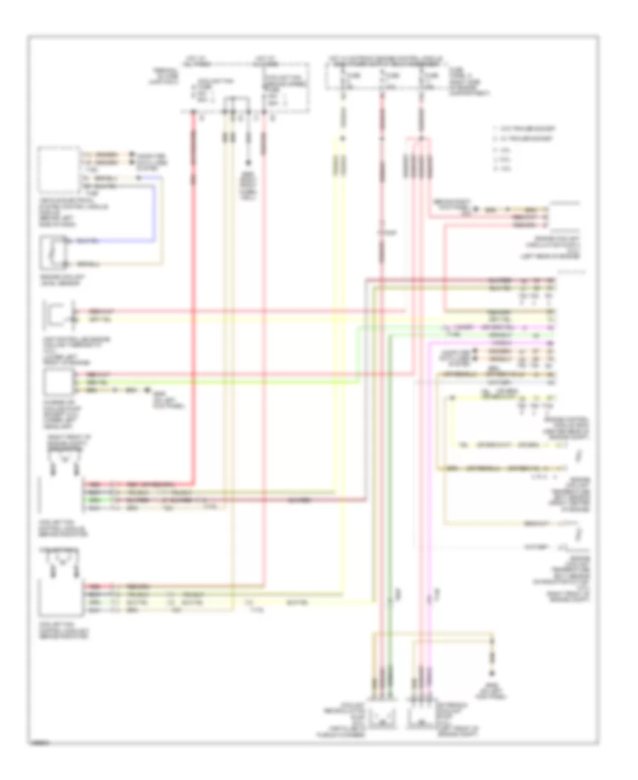
COOLING FAN
Cooling Fan Wiring Diagram for Audi S8 2013
List of elements for Cooling Fan Wiring Diagram for Audi S8 2013:
- (behind right kick panel) g43
- (right front of engine compt) coolant fan
- 11a
- 3.0l
- 4.0l
- 40a
- 6.3l
- 60a
- After-run coolant pump (4.0l) (left front of engine compt)
- Charge air cooling pump (except 6.3l) (under left headlamp)
- Computer data lines system
- Coolant fan 2
- Coolant fan control module (behind radiator)
- Coolant fan control module 2 (behind radiator)
- Coolant fan fuse
- Coolant fan second speed fuse
- Coolant recirculation pump (6.3l) (installed in plenum chamber)
- Engine control module (ecm) (center rear of engine compt)
- Engine coolant circulation pump 2 (4.0l) (left rear of engine)
- Engine coolant level sensor
- Engine coolant temperature (ect) sensor (front center of engine)
- Engine coolant temperature (ect) sensor on radiator outlet (4.0l) (right front of engine compt)
- Fuse 10a
- Fuse 15a
- Fuse 5a
- Fuse panel a (right side of engine compartment)
- G639 (on left kick panel)
- G685 (right front wheel well)
- Hot at all times
- Map controlled engine cooling thermostat (4.0l) (lower left front of engine)
- Nca
- Red
- T105
- T14b
- T16c
- T17g
- T2t
- T2u
- T32b
- T60
- T8ap
- T91
- T94
- Terminal 30 wire junction 2
- Vehicle electrical system control module module (behind left side of dash)
- W/ trailer socket
- W/o trailer socket
 Čeština
 Dansk
Dansk Deutsch
 Ελληνικά
 English
 English
 Suomi
Suomi Français
 Français
 עברית
עברית Hrvatski
 Magyar
 Italiano
 日本語
日本語 한국어
한국어 Nederlands
 Polski
 Português
 Português
 Română
 Русский
 Slovenčina
 Slovenščina
 Svenska
 Türkçe
 中文 (中国)
 Español