POWER DISTRIBUTION
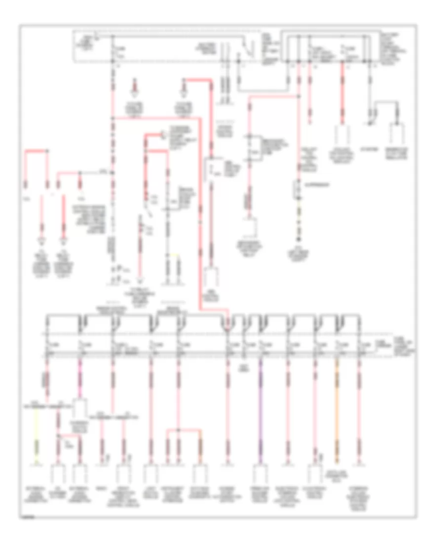
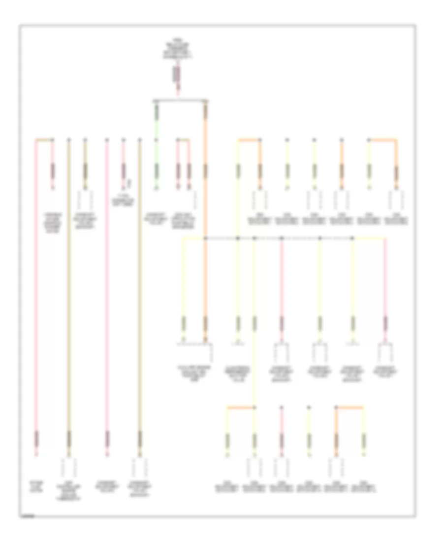
Power Distribution Wiring Diagram (1 of 7) for Audi A5 Quattro 2009
 https://portal-diagnostov.com/license.html
Automotive Electricians Portal FZCO
Automotive Electricians Portal FZCO
https://portal-diagnostov.com/license.html
https://portal-diagnostov.com/license.html
Automotive Electricians Portal FZCO
Automotive Electricians Portal FZCO
List of elements for Power Distribution Wiring Diagram (1 of 7) for Audi A5 Quattro 2009:
- 10a
- 11a
- 12a
- 40a
- A/c pressure/ temperature sensor
- Abs control module
- Active steering control module
- Air quality sensor (w/ comfort)
- All drive control module
- Automatic day/night interior mirror
- Battery
- Battery monitoring control module (at battery)
- Clutch position sensor (m/t)
- Comfort system central control module
- Data bus on board diagnostic interface
- Directional stabilization assistance control module
- Discontinued (phased in modification)
- Electronic damping control module
- Fuse 10a
- Fuse 110a
- Fuse 5a
- Fuse carrier 1
- Fuse panel sc (under left side of dash)
- G624 (near starter battery)
- Garage door opener control head
- Garage door opener control module
- Generator & voltage regulator
- Headlamp range control module
- Headlamp range/ cornering lamp control module
- Left headlamp assembly (w/ cornering lamps)
- Left washer nozzle heater
- Main fuse panel sa (on battery, in luggage compt)
- Nca
- Phased in modification
- Rear window defogger fuse
- Rear window defogger relay
- Red
- Right headlamp assembly
- Right washer nozzle heater
- Selector lever sensor system control module
- Shift lock solenoid
- T32b
- T32d
- T8g
- To fuse 2 (diagram 2 of 7)
- To fuse panel sc (diagram 7 of 7)
- To fuse panel sd (diagram 4 of 7)
- To relay/ fuse carrier e box sb (diagram 5 of 7)
- To relay/ fuse carrier luggage compartment sf (diagram 3 of 7)
- To relay/ fuse carrier luggage compartment sf (diagram 4 of 7)
- To sockets relay (diagram 4 of 7)
- Vehicle electrical system control module
- W/ cornering lamps
- W/ heated spray jet
- W/o cornering lamps
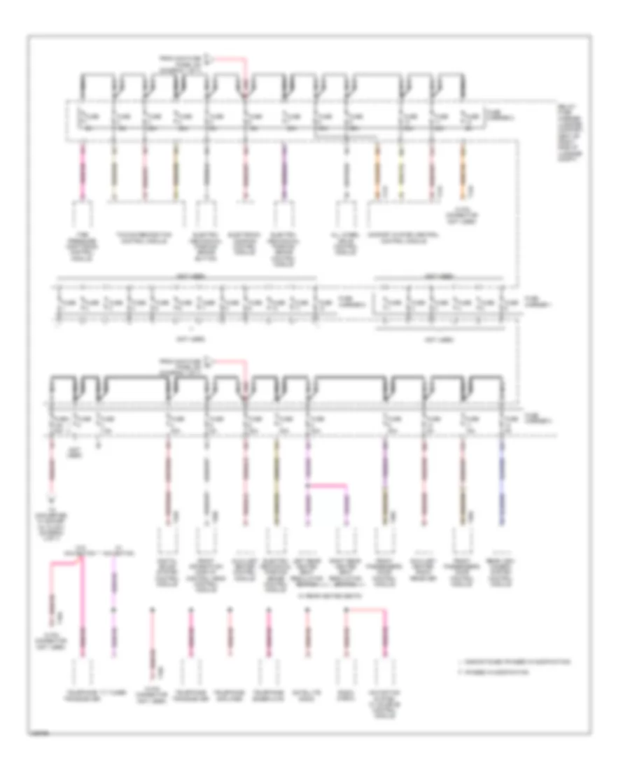
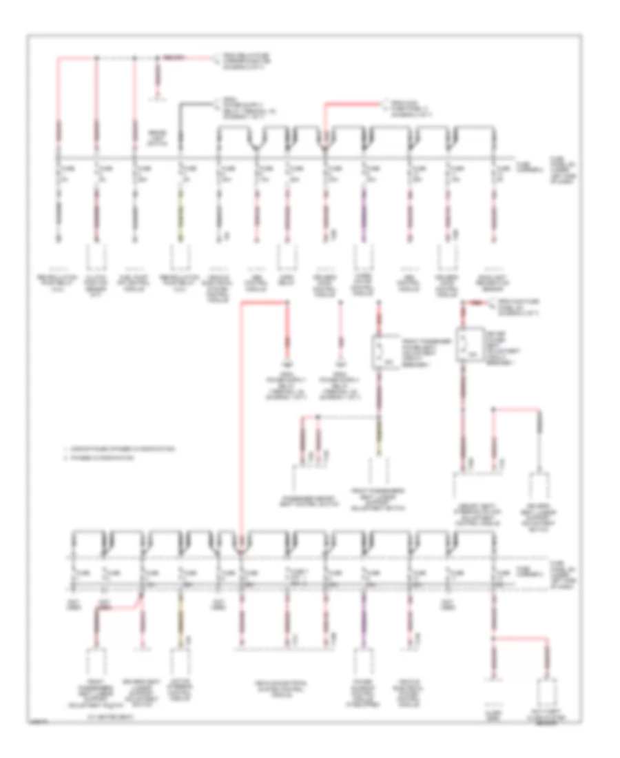
Power Distribution Wiring Diagram (2 of 7) for Audi A5 Quattro 2009
List of elements for Power Distribution Wiring Diagram (2 of 7) for Audi A5 Quattro 2009:
- (400w) (except 400w)
- (not used)
- (w/ mmi) (radio)
- 10a
- 11a
- 12a
- 15a
- 3.2l
- 4.2l
- 40a
- 50a
- Abs control module
- Abs control module fuse 1
- Access/ start authorization switch
- Air bag control module
- Battery interrupt igniter
- Battery jump start terminal (on terminal 30 wire junction block)
- Brake booster relay
- Brake vacuum pump fuse (4.2l)
- Cd changer (w/ high)
- Charisma switch module
- Climatronic control module
- Coolant fan control (fc) control module
- Coolant fan control (fc) control module 2
- Data bus on board diagnostic
- Data link connector (dlc)
- Electronic steering column lock control module
- Engine control module (ecm)
- External audio source connection
- Fresh air blower control module
- From a fuse 1 (diagram 1 of 7)
- Front information display control head control module
- Fuse
- Fuse (1000w) 40a
- Fuse 1 40a 60a
- Fuse 10a
- Fuse 110a
- Fuse 3 10a 20a
- Fuse 40a
- Fuse 5a
- Fuse carrier
- Fuse panel sd (under right side of dash)
- G12 (left rear of engine compt)
- Generator & voltage regulator
- Instrument cluster control interface
- Light switch module
- Main fuse panel sa (on battery, in luggage compt)
- Nca
- Radio
- Red
- Secondary air injection (air) pump fuse
- Secondary air injection (air) pump relay
- Starter
- Steering column electronic systems control module
- Suppressor
- T16j
- T16l
- T20e
- T94
- To fuse panel sc (diagram 7 of 7)
- To relay/ fuse carrier e box sb (diagram 5 of 7)
- To relay/ fuse carrier e e box sb (diagram 5 of 7)
- W/ high
- W/ navigation
- W/o navigation
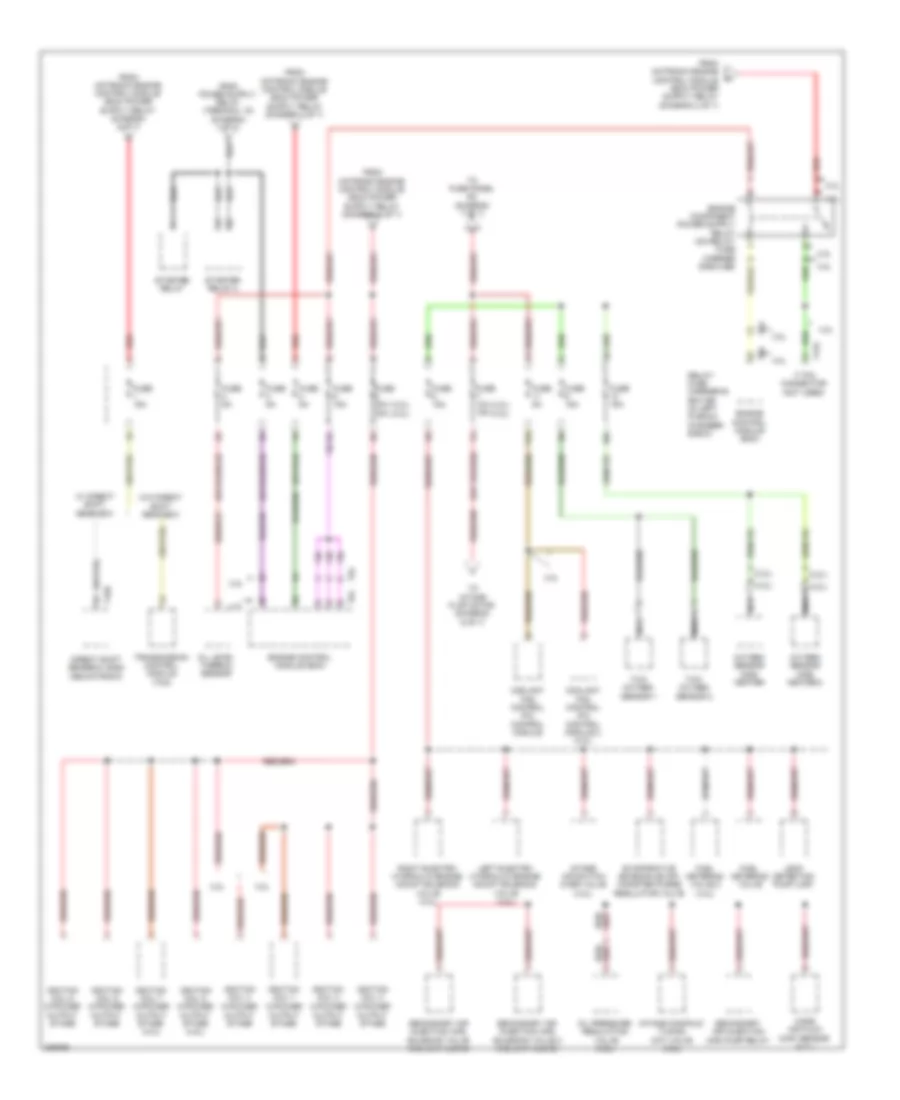
Power Distribution Wiring Diagram (3 of 7) for Audi A5 Quattro 2009
List of elements for Power Distribution Wiring Diagram (3 of 7) for Audi A5 Quattro 2009:
- (not used)
- 10a
- 11a
- 12 pin connector (not used)
- 12a
- 18 pin connector (not used)
- All wheel drive control module
- Auxiliary heater control module
- Auxiliary heater radio receiver
- Comfort system central control module
- Digital sound system control module
- Discontinued (phased in modification)
- Electro- mechanical parking brake button
- Electro- mechanical parking brake control module
- Electronic damping control module
- From main fuse panel sa (diagram 1 of 7)
- Front information display control head control module
- Front passenger's door control module
- Fuse
- Fuse 1 15a 30a
- Fuse 15a
- Fuse 20a
- Fuse 30a
- Fuse 35a
- Fuse 5a
- Fuse 7.5a
- Fuse carrier 1
- Fuse carrier 2
- Fuse carrier 3
- Fuse carrier 5
- Left rear heated seat regulating switch
- Navigation system w/ cd drive control module
- Nca
- Phased in modification
- Radio (k-box)
- Rear view camera system control module
- Red
- Relay/ fuse carrier luggage compart- ment sf (right side of luggage compt)
- Right rear heated seat regulating switch
- Satellite radio
- T12u
- T17o
- T17p
- T18a
- T20b
- T20g
- T32h
- Telephone amplifier
- Telephone baseplate
- Telephone transceiver
- Tire pressure monitoring control module
- To converter w/ socket 12v & 230v (diagram 4 of 7)
- Towing recognition control module
- Tv tuner
- W/ navigation
- W/ rear heated seats
- W/o navigation
Power Distribution Wiring Diagram (4 of 7) for Audi A5 Quattro 2009
List of elements for Power Distribution Wiring Diagram (4 of 7) for Audi A5 Quattro 2009:
- (not used)
- 1, 2 & 3
- 1, 2, 3 & 4
- 10a
- 11a
- 12 v socket (if equipped)
- 12 v socket 2 (if equipped)
- 12 v socket 3 (if equipped)
- 12a
- 18 pin connector (not used)
- Air bag control module
- Asr/esp button
- Cigarette lighter
- Comfort system central control module
- Converter w/ socket, 12v & 230v (if equipped)
- Data bus on board diagnostic interface
- Data link connector (dlc)
- Distance regulation control module
- Electro- mechanical parking brake button
- From converter w/ socket 12v & 230v (diagram 4 of 7)
- From main fuse panel sa (diagram 1 of 7)
- From relay/fuse carrier luggage compartment sf (diagram 3 of 7)
- Front passenger's air bag disabled indicator lamp
- Fuse
- Fuse 15a
- Fuse 5a
- Fuse carrier 1
- Fuse carrier 4
- Fuse panel sd (under right side of dash)
- G51 (right side of luggage compt)
- G663 (on right "c" pillar)
- G688 (right side of center tunnel)
- Interior lights system
- Lane change assistance control module
- Lane change assistance control module 2
- Left rear heated seat regulating switch
- Nca
- Parallel parking assistance control module
- Red
- Relay/ fuse carrier luggage compartment sf (right side of luggage compt)
- Right rear heated seat regulating switch
- Seat occupied recognition control module
- Sockets relay (on relay/fuse carrier - sf, at right side of luggage compt)
- Steering column electronic systems control module
- T16e
- T18a
- T32c
- To relay/fuse carrier luggage compartment sf (diagram 4 of 7)
- W/ converter & socket 12v, 230v
- W/ converter, socket, 12v, 230v &
- W/o 12 v socket in backside of the center console & luggage compartment
- W/o converter & w/ socket 12v & 230v
- W/o converter, w/ socket, 12v, 230v &
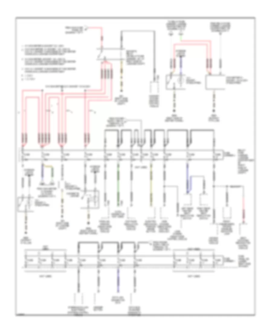
Power Distribution Wiring Diagram (5 of 7) for Audi A5 Quattro 2009
List of elements for Power Distribution Wiring Diagram (5 of 7) for Audi A5 Quattro 2009:
- (3.2l)
- (3.2l) (4.2l)
- (4.2l)
- (4.2l) (3.2l)
- 10a
- 11a
- 17 pin connector (not used)
- 3.2l
- 4.2l
- Coolant fan control (fc) control module
- Coolant fan control (fc) control module 2 (4.2l)
- Direct shift gearbox (dsg) mechatronic
- Engine control module (ecm)
- Evaporative emission (evap) canister purge regulator valve
- Fuel metering valve
- Fuel metering valve 2 (4.2l)
- Fuse 10a 15a
- Fuse 15a
- Fuse 20a 30a
- Fuse 5a
- Ignition coil 1
- Ignition coil 2
- Ignition coil 3
- Ignition coil 4
- Ignition coil 5 w/power output stage
- Ignition coil 6 w/power output stage
- Ignition coil 7 w/power output stage (4.2l)
- Ignition coil 8 w/power output stage (4.2l)
- Intake air switch over valve (4.2l)
- Intake manifold tuning (imt) valve (3.2l)
- Leak detection pump (ldp)
- Left electro hydraulic engine mount solenoid valve (4.2l)
- Mass air flow (maf) sensor (4.2l)
- Nca
- Oil level thermal sensor
- Oil pressure regulation valve (3.2l)
- Oxygen sensor (o2s) heater
- Oxygen sensor (o2s) heater 2
- Red
- Relay/ fuse carrier e- box sb (in left plenum chamber e-box)
- Right electro hydraulic engine mount solenoid valve (4.2l)
- Secondary air injection (air) pump relay
- Secondary air injection (air) solenoid valve (3.2l & w/ ulev2)
- Secondary air injection (air) solenoid valve 2 (3.2l & w/ ulev2)
- Starter relay
- Starter relay 2
- T16r
- T17q
- T94
- To fuse panel sc (diagram 7 of 7)
- To intake flap motor (diagram 6 of 7)
- Transmission control module (tcm)
- Twc oxygen sensor 1
- Twc oxygen sensor 2
- W/ direct shift gear box
- W/o direct shift gear box
- W/power output stage
Power Distribution Wiring Diagram (6 of 7) for Audi A5 Quattro 2009
List of elements for Power Distribution Wiring Diagram (6 of 7) for Audi A5 Quattro 2009:
- 17 pin connector (not used)
- 3.2l
- 4.2l
- Auxiliary engine coolant (ec) pump relay (8z9)
- Cam adjustment actuator 1
- Cam adjustment actuator 10
- Cam adjustment actuator 11
- Cam adjustment actuator 12
- Cam adjustment actuator 2
- Cam adjustment actuator 3
- Cam adjustment actuator 4
- Cam adjustment actuator 5
- Cam adjustment actuator 6
- Cam adjustment actuator 7
- Cam adjustment actuator 8
- Cam adjustment actuator 9
- Camshaft adjustment valve 1
- Camshaft adjustment valve 1 (exhaust)
- Camshaft adjustment valve 2
- Camshaft adjustment valve 2 (exhaust)
- Climatronic refrigerant shut-off valve
- Coolant circulation pump relay (8z4/8z6/8z9)
- From relay/fuse carrier e box sb fuse 7 (diagram 5 of 7)
- Intake flap motor
- Map controlled engine cooling thermostat
- T17q
- Variable intake manifold runner motor
Power Distribution Wiring Diagram (7 of 7) for Audi A5 Quattro 2009
List of elements for Power Distribution Wiring Diagram (7 of 7) for Audi A5 Quattro 2009:
- (not used)
- (w/ heated seat)
- 10a
- 11a
- 12a
- 15a
- Abs control module
- Active steering control module
- Alarm horn
- Anti-theft alarm system sensor
- Brake light switch
- Clutch position sensor (m/t)
- Discontinued (phased in modification)
- Driver power seat adjustment circuit breaker 1
- Driver's door control module
- Driver's seat lumbar support adjustment switch
- From main fuse panel a (diagram 2 of 7)
- From main fuse panel sa (diagram 2 of 7)
- From relay/fuse carrier e box sb (diagram 5 of 7)
- Front passenger power seat adjustment circuit breaker 1
- Front passenger's seat lumbar support adjustment switch
- Fuel pump (fp) control module
- Fuse
- Fuse 10a
- Fuse 15a
- Fuse 20a
- Fuse 25a
- Fuse 30a
- Fuse 35a
- Fuse 5a
- Fuse 7 30a 20a
- Fuse carrier 2
- Fuse carrier 3
- Fuse panel sc (under left side of dash)
- Horn relay
- Memory seat/ steering column adjustment control module
- Nca
- Passenger memory seat control switch
- Phased in modification
- Power sunroof control module (if equipped)
- Rain/light recognition sensor
- Recirculation pump relay (3.2l)
- Red
- T12l
- T12o
- T17l
- T17m
- T17n
- T20f
- T32g
- T32i
- T5d
- T6f
- Vehicle electrical system control module
- Wiper motor control module

 Čeština
 Dansk
Dansk Deutsch
 Ελληνικά
 English
 English
 Suomi
Suomi Français
 Français
 עברית
עברית Hrvatski
 Magyar
 Italiano
 日本語
日本語 한국어
한국어 Nederlands
 Polski
 Português
 Português
 Română
 Русский
 Slovenčina
 Slovenščina
 Svenska
 Türkçe
 中文 (中国)