CRUISE CONTROL
4.4L VIN D
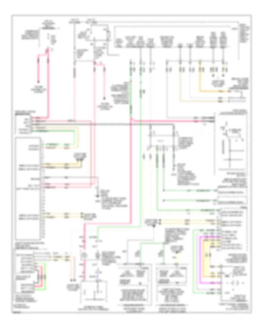
4.4L VIN D, Conventional Cruise Control Wiring Diagram for Cadillac XLR V 2007
 https://portal-diagnostov.com/license.html
Automotive Electricians Portal FZCO
Automotive Electricians Portal FZCO
https://portal-diagnostov.com/license.html
https://portal-diagnostov.com/license.html
Automotive Electricians Portal FZCO
Automotive Electricians Portal FZCO
List of elements for 4.4L VIN D, Conventional Cruise Control Wiring Diagram for Cadillac XLR V 2007:
- (behind lower left side of dash) brake pedal position sensor
- (behind rear compt stowage trim panel) rear object sensor control module
- (not used)
- (not used) c1
- (right side of engine compt, under battery) g104
- 5 volt ref
- 5-volt ref-1
- 5-volt ref-2
- A iss signal
- A15
- Acc gap adjust switch signal
- Acceleration pedal position (app) sensor (top of accelerator pedal assembly)
- App sen 1 sig
- App sen 2 sig
- Automatic transmission
- B batt + vol
- Batt + vol
- Batt5 fuse 30a
- Battery positive voltage
- Body control module (bcm) (behind right right side of dash)
- Brake pedal position switch signal
- C oss signal
- Computer data lines system
- Cruise control switch
- Cruise ctrl set/coast & resume/ accel sw signal
- Cruise speed set xxx
- D12
- Data bus +
- Data bus -
- Engine control module (ecm) (lower right rear of engine compt)
- Ground
- Heads up display (hud) (top left side of dash)
- High speed gmlan serial data bus +
- High speed gmlan serial data bus -
- Hot at all times
- Hud message center
- Inflatable restraint steering wheel module coil (in steering wheel)
- Input/output speed sensors (iss/oss) assembly
- Instrument panel cluster (ipc)
- Iss signal
- Logic
- Low ref
- Low reference
- Message request
- Nca
- Off
- Oss signal
- Pnk
- Radio
- Red
- Resume/ accel +
- S211 (in instrument panel harness, approximately 25 cm from park brake pedal assembly breakout)
- S232
- S276 (in instrument panel harness, approximately 14.5 cm from breakout to automatic transmission shift lever)
- Serial data bus +
- Serial data bus -
- Set/coast
- Stop lamp sw sig
- Stop lamp switch signal
- Switch signal
- Tac motor ctrl-1
- Tac motor ctrl-2
- Tan
- Tehc module assembly
- Throttle actuator control (tac) motor
- Throttle body assembly (top of engine, at intake manifold)
- Throttle position (tp) sensor
- Tp sen 1 sig
- Tp sen 2 sig
- Turn signal/ multifunction switch
- Underhood fuse block (right rear of engine compt)
- Vehicle speed sig
- Vehicle speed signal
- Vehicle speed signal hud class 2 serial data
4.6L VIN A
4.6L VIN A, Adaptive Cruise Control Wiring Diagram for Cadillac XLR V 2007
List of elements for 4.6L VIN A, Adaptive Cruise Control Wiring Diagram for Cadillac XLR V 2007:
- (behind lower left side of dash) brake pedal position sensor
- (behind rear compt stowage trim panel) rear object sensor control module
- (in instrument panel harness, approxi- mately 25 cm from park brake pedal assembly breakout) s211
- 5 volt ref
- 5-volt ref 2
- A iss signal
- Acc gap adjust switch signal
- Acc/ tcm fuse 10a
- Acca/driv dr sw fuse 10a
- Adaptive cruise control module (acm) (center of vehicle)
- Alert distance cruise speed limited follow distance set speed set xx mph tight curve
- Automatic transmission
- B batt + vol
- Batt
- Batt + vol
- Batt positive volt
- Bcm high speed gmlan serial data bus +
- Bcm high speed gmlan serial data bus -
- Body control module (bcm) (behind right side of dash)
- Brake pedal position switch signal
- C oss signal
- C1 a15
- C10
- C5 d
- Can bus +
- Can bus -
- Clean radar cruise cruise disengage cruise not ready cruise set xx mph service radar cruise
- Computer data lines system
- Cruise control switch
- Cruise ctrl set/coast & resume/ accel sw signal
- Data bus +
- Data bus -
- E11
- Engine control module (ecm) (lower right rear of engine compt)
- Forward looking sensor (fls)
- G102
- G302
- Gnd
- Ground
- Heads up display (hud) (top left side of dash)
- Hot at all times
- Hot w/ run/crank relay energized
- Hud class 2 serial data
- Hud message center
- Ign 1
- Ign 1 volt
- Inflatable restraint steering wheel module coil (in steering wheel)
- Input/output speed sensors (iss/oss) assembly
- Instrument panel cluster (ipc)
- Iss signal
- Logic
- Low ref
- Message center
- Message request
- Nca
- Off
- Oss signal
- Pnk
- Power distribution system
- Radio
- Red
- Resume/ accel +
- Run/ crank relay
- Run/ crank rly ctrl
- S240
- S276 (in instrument panel harness, approximately 14.5 cm from breakout to automatic transmission shift lever)
- Serial data bus +
- Serial data bus -
- Set/coast
- Splice pack sp102 (in forward lamp harness, in engine compt, on upper right frame rail, grounded to g102)
- Splice pack sp302 (in instrument panel harness, on right "b" pillar behind trim panel, grounded to g302)
- Steering wheel control switch assembly
- Stop lamp sw sig
- Stop lamp switch signal
- Switch signal
- Tac motor ctrl-1
- Tac motor ctrl-2
- Tan
- Tehc module assembly
- Throttle actuator control (tac) motor
- Throttle body assembly (top of engine, at intake manifold)
- Throttle position (tp) sensor
- Tp sens 1 sig
- Tp sens 2 sig
- Turn signal/ multifunction switch
- Tutd sw/ strg col sw fuse 2a
- Underhood fuse block (right rear of engine compt)
- Vehicle speed sig
- Vehicle speed signal

 Čeština
 Dansk
Dansk Deutsch
 Ελληνικά
 English
 English
 Suomi
Suomi Français
 Français
 עברית
עברית Hrvatski
 Magyar
 Italiano
 日本語
日本語 한국어
한국어 Nederlands
 Polski
 Português
 Português
 Română
 Русский
 Slovenčina
 Slovenščina
 Svenska
 Türkçe
 中文 (中国)