ANTI-THEFT
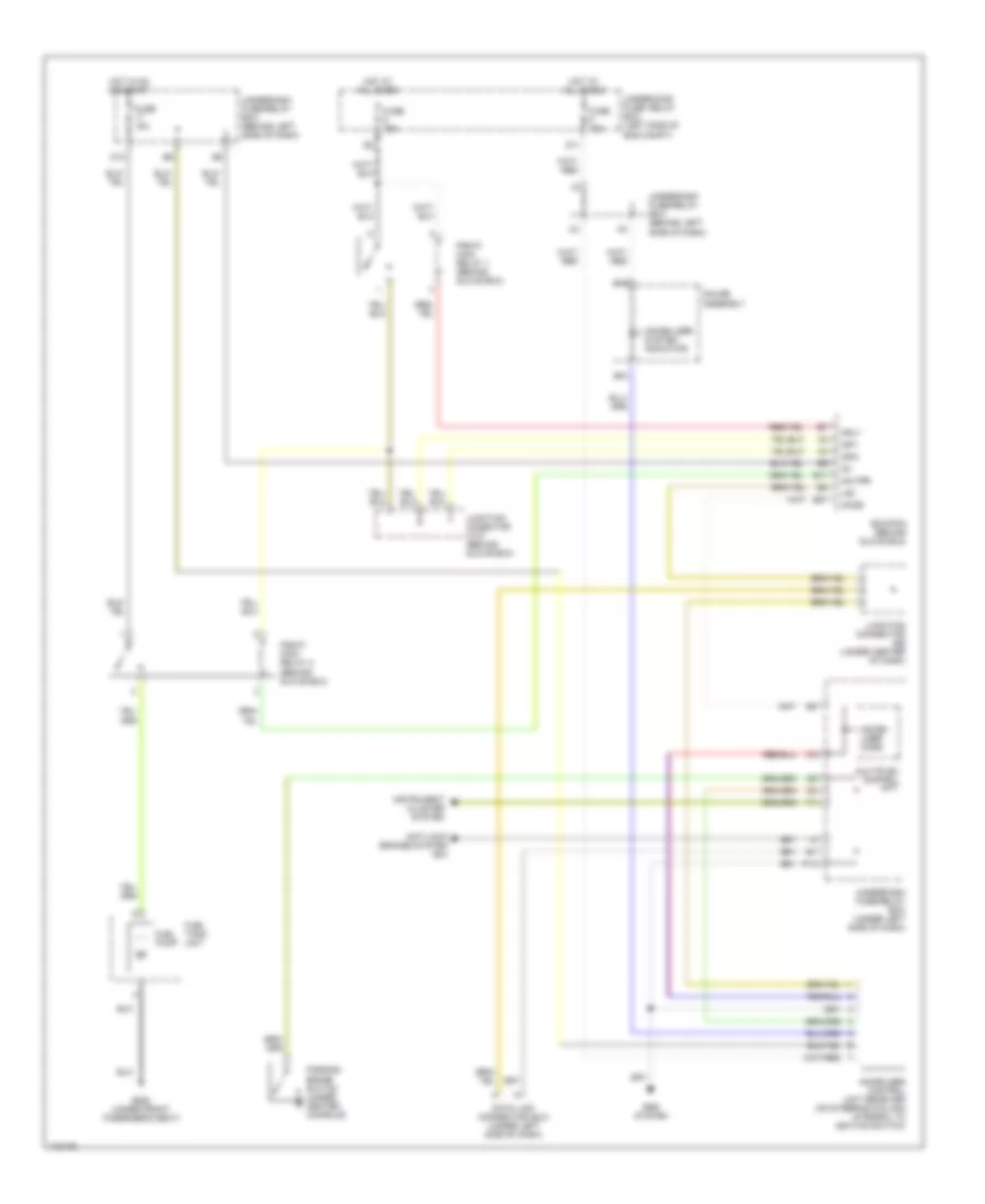
Forced Entry Wiring Diagram for Honda Element LX 2004
 https://portal-diagnostov.com/license.html
Automotive Electricians Portal FZCO
Automotive Electricians Portal FZCO
https://portal-diagnostov.com/license.html
https://portal-diagnostov.com/license.html
Automotive Electricians Portal FZCO
Automotive Electricians Portal FZCO
List of elements for Forced Entry Wiring Diagram for Honda Element LX 2004:
- (not used)
- Back up (b+)
- C11
- Combination switch
- D11
- Driver's door switch
- Drl h/l sw
- Fr door sw
- Front passenger's door switch
- Fuse 10a
- Fuse 15a
- Fuse 7.5a
- G401 (under center of dash)
- G501 (under left side of dash)
- G553 (left "d" pillar)
- Hatch latch switch
- Headlight switch
- Horn
- Horn relay
- Horn sw
- Horns system
- Hot at all times
- Hot in on or start
- Ig1 meter
- Ignition key switch
- Ignition key switch/key light
- Interior lights system
- Junction connector 456 (under center of dash)
- K/l set
- K/l unset
- K13
- Key sw
- Keyless receiver unit (optional) (under center of dash)
- Left tailgate switch
- Lighting rly
- Microphone
- Multiplex control unit
- Nca
- Other door sw
- P18
- Red
- Right tailgate switch
- Security control unit (under left side of dash)
- Security led
- Small lt rly
- Trunk sw
- Underdash fuse/relay box (under left side of dash)
- Underhood fuse/relay box (on left side of engine compartment)
Immobilizer Wiring Diagram for Honda Element LX 2004
List of elements for Immobilizer Wiring Diagram for Honda Element LX 2004:
- Anti-lock brakes system (ex)
- B15
- B16
- D11
- D12
- Data link connector (dlc) (under left side of dash)
- E17
- E27
- Ecm/pcm (behind glove box)
- Fuel pump
- Fuel tank unit
- Fuse 10a
- Fuse 15a
- G552 (under front pasenger's seat)
- Gauge assembly
- Hot at all times
- Hot in on or start
- Ig1
- Igp1
- Igp2
- Immobi- lizer code
- Immobilizer system indicator
- Immoblizer control unit receiver (on steering column integral to ignition switch)
- Imo fpr
- Imocd
- Instrument cluster system
- Junction conector c107 (behind glove box)
- Junction connector (under center of dash)
- Lg3
- Mrly
- Multiplex control unit
- P14
- Parking brake switch (under center console)
- Pgm-fi main relay 1 (behind glove box)
- Pgm-fi main relay 2 (behind glove box)
- Srs system
- Underdash fuse/relay box (behind left side of dash)
- Underdash fuse/relay box (under left side of dash)
- Underhood fuse/ relay box (left side of eng compt)

 Čeština
 Dansk
Dansk Deutsch
 Ελληνικά
 English
 English
 Suomi
Suomi Français
 Français
 עברית
עברית Hrvatski
 Magyar
 Italiano
 日本語
日本語 한국어
한국어 Nederlands
 Polski
 Português
 Português
 Română
 Русский
 Slovenčina
 Slovenščina
 Svenska
 Türkçe
 中文 (中国)