AUTOMOTIVE ELECTRICIANS PORTAL

SUPPLEMENTAL RESTRAINTS – Honda Odyssey Touring 2009 – SYSTEM WIRING DIAGRAMS

SUPPLEMENTAL RESTRAINTS

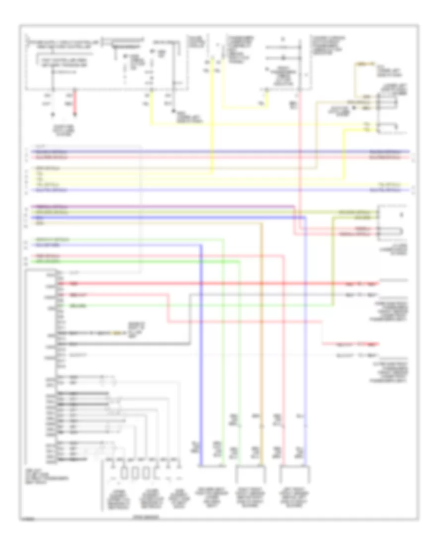
Supplemental Restraints Wiring Diagram (1 of 3) for Honda Odyssey Touring 2009

Supplemental Restraints Wiring Diagram (1 of 3) for Honda Odyssey Touring 2009 https://portal-diagnostov.com/license.html
https://portal-diagnostov.com/license.html Automotive Electricians Portal FZCO Automotive Electricians Portal FZCO
Download PDF file

List of elements for Supplemental Restraints Wiring Diagram (1 of 3) for Honda Odyssey Touring 2009:

  • (base of left "b" pillar) g602
  • (base of right "b" pillar) g651
  • (behind right kick panel)
  • A10
  • A11
  • A12
  • A13
  • A14
  • A15
  • A16
  • A17
  • A18
  • A19
  • A20
  • A21
  • A22
  • A23
  • A24
  • A25
  • A26
  • A27
  • A28
  • B10
  • B11
  • B12
  • B13
  • B14
  • B15
  • B16
  • B17
  • B18
  • B19
  • B20
  • B21
  • B22
  • B23
  • B24
  • B25
  • B26
  • B27
  • B28
  • Buck- led
  • Built-in short contact
  • Cable reel
  • Check in
  • Computer data lines
  • Computer data lines system
  • Connector
  • Driver's airbag first inflator
  • Driver's airbag second inflator
  • Driver's seat belt buckle switch (under driver's seat)
  • Driver's seat belt tensioner (base of driver's "b" pillar)
  • Driver's side airbag inflator (under driver's seat)
  • Driver's under-dash fuse/relay box (behind left kick panel)
  • F-can+
  • F-can-
  • F14
  • Flbc
  • Flbo
  • Frbc
  • Frbo
  • Front passenger's seat belt buckle switch (under front passenger's seat)
  • Front passenger's seat belt tensioner (base of front passenger's "b" pillar)
  • Front passenger's side airbag inflator (under front passenger's seat)
  • Fuse 10a
  • Fuse 7.5a
  • G505
  • G505 (behind right kick panel)
  • Gnda
  • Gndb
  • H14
  • Hot in on or start
  • Ign in
  • K-line
  • La1+
  • La1-
  • La2+
  • La2-
  • Lbsi+
  • Lbsi-
  • Left side impact sensor (1st) (base of left "b" pillar)
  • Lfs+
  • Lfs-
  • Lrp+
  • Lrp-
  • Lsa+
  • Lsa-
  • Mes
  • Mes conn
  • Micu
  • N41
  • Ods
  • Ptt
  • Ra1+
  • Ra1-
  • Ra2+
  • Ra2-
  • Rbsi+
  • Rbsi-
  • Red
  • Rfs+
  • Rfs-
  • Right side impact sensor (1st) (base of right "b" pillar)
  • Rrp+
  • Rrp-
  • Rsa+
  • Rsa-
  • Seat belt sw
  • Srs unit (under middle of dash)
  • Ss+
  • Ss-
  • Steering wheel
  • System
  • Terminal has
  • Un-
  • X34

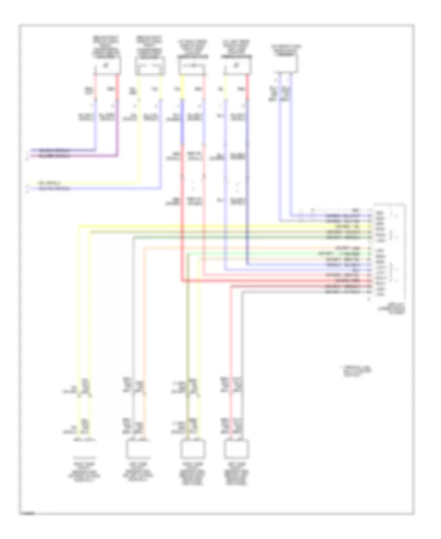
Supplemental Restraints Wiring Diagram (2 of 3) for Honda Odyssey Touring 2009

Supplemental Restraints Wiring Diagram (2 of 3) for Honda Odyssey Touring 2009 https://portal-diagnostov.com/license.html
https://portal-diagnostov.com/license.html Automotive Electricians Portal FZCO Automotive Electricians Portal FZCO
Obtenga acceso a todos los diagramas de cableado del cocheDownload PDF file

List of elements for Supplemental Restraints Wiring Diagram (2 of 3) for Honda Odyssey Touring 2009:

  • (base of right "b" pillar) g651
  • (under front
  • (under left side of dash) j/c c503
  • 0s2s
  • A21
  • A23
  • A24
  • Area network controller
  • Computer data lines
  • Computer data lines system
  • D10
  • D11
  • D12
  • D13
  • D14
  • D15
  • D16
  • D17
  • D18
  • Dlc (under left side of dash
  • Drive circuit
  • Driver's seat position sensor (under driver's seat)
  • Fast controller area
  • Front passenger's airbag cut-off indicator
  • G502 (under left side of dash)
  • Gauge control module
  • Gnd
  • Hazard warning switch/front passenger's airbag cut-off indicator
  • Inner side front passenger's weight sensor
  • J/c c506 (under middle of dash)
  • Left front impact sensor (behind left side of front bumper)
  • Lower element (lower four sensors in seatback)
  • Nca
  • Network transceiver
  • Ods
  • Ods unit (in left side of front passenger's seat back)
  • Opds sensor
  • Os1l
  • Os1s
  • Os2l
  • Os3l
  • Os3s
  • Os4l
  • Os4s
  • Os5l
  • Os5s
  • Os6l
  • Os6s
  • Os7l
  • Os7s
  • Outer side front passenger's weight sensor
  • Passenger's seat)
  • Passenger's under-dash fuse/relay box (behind right kick pannel)
  • Pow
  • Red
  • Right front impact sensor (behind right side of front bumper)
  • Side airbag cut-off ind
  • Side element (right side of seat back)
  • Srs ind
  • System
  • Upper element (upper two sensors in seatback)
  • Wsig
  • Wsip
  • Wsog
  • Wsop

Supplemental Restraints Wiring Diagram (3 of 3) for Honda Odyssey Touring 2009

Supplemental Restraints Wiring Diagram (3 of 3) for Honda Odyssey Touring 2009 https://portal-diagnostov.com/license.html
https://portal-diagnostov.com/license.html Automotive Electricians Portal FZCO Automotive Electricians Portal FZCO
Obtenga acceso a todos los diagramas de cableado del cocheDownload PDF file

List of elements for Supplemental Restraints Wiring Diagram (3 of 3) for Honda Odyssey Touring 2009:

  • (at left rear side of roof) left side curtain airbag inflator
  • (at right rear side of roof) right side curtain airbag inflator
  • (behind right side of dash) front passenger's airbag first inflator
  • (behind right side of dash) front passenger's airbag second inflator
  • (on rear floor) rear safing sensor
  • Built-in short contact
  • Gnd
  • Lca1+
  • Lca1-
  • Lcsi+
  • Lcsi-
  • Ldsi+
  • Ldsi-
  • Left side impact sensor (2nd) (on left sliding door sill)
  • Left side impact sensor (3rd) (behind left rear side trim panel)
  • Rca1+
  • Rca1-
  • Rcsi+
  • Rcsi-
  • Rdsi+
  • Rdsi-
  • Red
  • Right side impact sensor (2nd) (on right sliding door sill)
  • Right side impact sensor (3rd) (behind right rear side trim panel)
  • Srs unit (under middle of dash)
  • Sss+
  • Sss-
  • Terminal has