TRANSMISSION
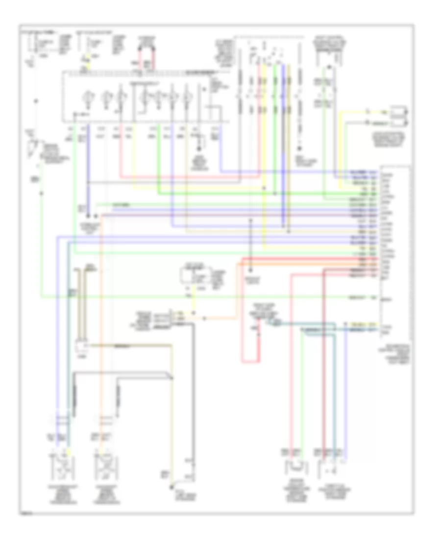
Transmission Wiring Diagram for Honda Odyssey LX 1996
List of elements for Transmission Wiring Diagram for Honda Odyssey LX 1996:
- (on trans-
- (right side
- (right side of dash) service check connector
- A/t gear position ind
- A/t gear position switch (below left side of shift lever)
- A12
- Atp1
- Atp2
- Atpd3
- Atpd4
- Atpnp
- Atpr
- Backup lights
- Bksw
- Brake switch (top of brake pedal support)
- C10
- C11
- C14
- C15
- C16
- C262
- C402
- C469
- C601
- Counter-shaft speed sensor (rear of transmission)
- D10
- D11
- D4ind
- Dimming circuit
- Ect
- Engine coolant temperature sensor (right side of engine)
- Fuse 1 10a
- Fuse 30 20a
- G114 (left rear of engine)
- G201
- G206 (behind front console)
- Gauge assembly
- Ground
- Hot at all times
- Hot in on or start
- Ignition
- Ilu
- Interior lights system
- Interlock control unit
- Lca
- Lcb
- Lock-up control solenoid valves (right front of engine compt)
- Main-shaft speed sensor (front of transmission)
- Mission)
- Ncsg
- Nmsg
- Of dash)
- Powertrain control module (front passengers foot rest)
- Red
- Scs
- Sg2
- Sha
- Shb
- Shift control solenoid valves (right front of engine compt)
- Throttle position sensor (right side of engine)
- Tps
- Under- dash fuse/ relay box
- Under- hood fuse/ relay box
- Vcc2
- Vehicle speed sensor
- Vss
- Vss out
- Wire braid
 Čeština
 Dansk
Dansk Deutsch
 Ελληνικά
 English
 English
 Suomi
Suomi Français
 Français
 עברית
עברית Hrvatski
 Magyar
 Italiano
 日本語
日本語 한국어
한국어 Nederlands
 Polski
 Português
 Português
 Română
 Русский
 Slovenčina
 Slovenščina
 Svenska
 Türkçe
 中文 (中国)
 Español