AIR CONDITIONING
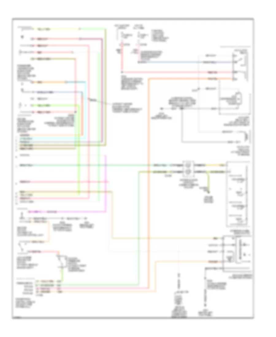
Automatic A/C Wiring Diagram (1 of 2) for Ford Expedition 2006
 https://portal-diagnostov.com/license.html
Automotive Electricians Portal FZCO
Automotive Electricians Portal FZCO
https://portal-diagnostov.com/license.html
https://portal-diagnostov.com/license.html
Automotive Electricians Portal FZCO
Automotive Electricians Portal FZCO
List of elements for Automatic A/C Wiring Diagram (1 of 2) for Ford Expedition 2006:
- (behind left kick panel) g301
- (behind right
- (behind right kick panel) g200
- (behind right side of dash) heater blower control module
- (in left side of dash) in-vehicle temperature/ humidity sensor
- (in main harness, near breakout to center of dash) s293
- (in main harness, near breakout to glove box lamp) s203
- (in main harness, near breakout to top of dash) s208
- (or 235)
- +/-
- Ambient air temperature sensor (behind right side of radiator grille)
- Auxiliary heater a/c circuit
- C228a
- C228b
- C270e
- C270g
- Central junction box (cjb) (behind right kick panel)
- Computer data lines system
- Defogger system
- Electronic automatic temperature control (eatc) module (in center of dash)
- Expedition
- Front blower motor relay
- Fuse 116 fuse 116 40a 40a
- Fuse 13 10a
- Fuse 5 7.5a
- G200 (behind right kick panel)
- Gnd
- Hot at all times
- Hot in start or run
- Hum sn
- Illum
- In temp
- In-vehicle temperature sensor (in left side of dash)
- Int temp
- Interior lights system
- Ms can+
- Ms can-
- Mtr ctrl
- Navigator
- Pos sig
- Pwr
- Remote solenoid assembly (under center of dash)
- Return
- Rr defr ind
- Rr defr req
- S203 (in main harness, near breakout to glove box lamp)
- S241 (main harness, near breakout to right side of dash)
- S277 (in main harness, near breakout to brake pedal position switch)
- Side of dash) heater blower motor
- Sig rtn
- Sn pwr
- Vbatt
- Vbc fb
- Vbc hbr
- Vbc pwm
- Vpwr
- Vref
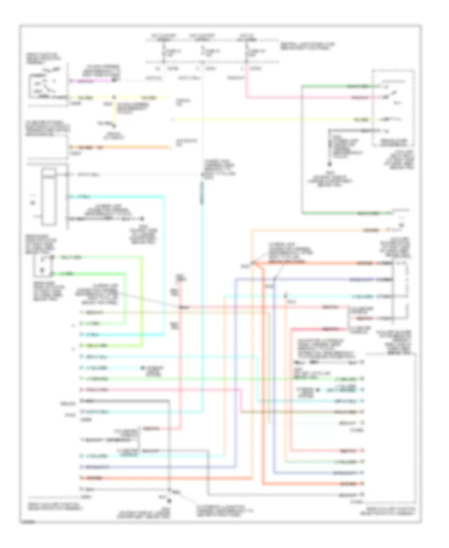
Automatic A/C Wiring Diagram (2 of 2) for Ford Expedition 2006
List of elements for Automatic A/C Wiring Diagram (2 of 2) for Ford Expedition 2006:
- (in engine control sensor harness, near
- (in engine control sensor harness, near breakout to g102) s113
- (in front heater blower motor harness, near breakout to right side of dash)
- A/c clutch field coil (at right front of engine)
- A/c clutch relay
- A/c compressor clutch diode
- A/c high pressure switch (at right front of engine compartment)
- Air bag sliding contact (under steering column)
- Auto lamps sens sig
- Auxiliary relay box 1 (at left front of engine compartment)
- Breakout to left side of engine compt) s104
- C175b
- C2113b
- C218b
- C270a
- C270b
- Central junction box (cjb) (behind right kick panel)
- Cruise control system
- De-icing switch (on front of climate control unit)
- Driver temperature blend door actuator (behind center of dash)
- Fan speed (+)
- Fan speed (-)
- Fuse 11 10a
- Fuse 32 15a
- G100 (near left side of radiator)
- G301 (behind left kick panel)
- Hot at all times
- Hot in start or run
- Low charge protection switch (at right rear of engine compt)
- Microprocessor
- Nca
- Passenger temperature blend door actuator (behind center of dash)
- Pats ind
- Powertrain control module (on right side of firewall)
- Pressure sw
- Red
- Rtn sig
- S103
- S105 (in engine control sensor harness, near breakout to left side of engine compt)
- S2025 (in front heater blower motor harness, near breakout to right side of dash)
- S2026
- S208 (in main harness, near breakout to top of dash)
- Steering wheel radio switch
- Sunload sensor (to center of dash)
- Tan
- Temp (+)
- Temp (-)
- Vehicle security module (vsm) (under right side of dash)
Auxiliary Heater-A/C Wiring Diagram for Ford Expedition 2006
List of elements for Auxiliary Heater-A/C Wiring Diagram for Ford Expedition 2006:
- (in body main harness, near breakout to right "c" pillar) s319
- (in center of dash) electronic automatic temperature control (eatc) module
- (in interior illumination harness, near breakout to center of roof panel)
- (in main harness, near breakout to right side of dash) s241
- (in rear lamp connector harness, near breakout after right "c" pillar, behind trim panel)
- (in rear lamp connector harness, near breakout to c410) s424
- (navigator: in console panel harness, near breakout to c315) (expedition: near breakout to storage bin power point)
- (not used)
- (or red/pnk)
- +/-
- Automatic a/c
- Auxiliary blower motor (at right side of cargo area, behind trim)
- Auxiliary blower motor resistor assembly (right side of cargo area, behind trim)
- Auxiliary relay box 2 (at right side of cargo area, behind trim)
- C228a
- C270e
- C270j
- C270n
- C294b
- C3198a
- C3198b
- C989a
- C989b
- Central junction box (cjb) (behind right kick panel)
- Def
- Floor
- Front auxiliary function selector switch assembly
- Front function selector switch assembly
- Fuse 107 30a
- Fuse 13 10a
- Fuse 18 10a
- G300 (on left ``b" pillar, behind trim)
- G404 (on right side of luggage compartment, behind trim)
- Ground
- Hot at all times
- Hot in start or run
- Interior lights system
- Manual a/c
- Manual a/c circuit
- Max
- Mix
- Nca
- Near breakout to c410)
- Norm
- Off
- Rear auxiliary function selector switch assembly
- Rear blend door actuator (at right side of cargo area, behind trim)
- Rear blower motor relay
- Rear mode door actuator (at right side of cargo area, behind trim)
- Red/ pnk
- Red/pnk
- S205
- S230 (in main harness, near breakout to c210)
- S412
- S423
- S431
- S432
- S904
- Vent
- Vpwr
- W/ center console
- W/o center console
Manual A/C Wiring Diagram for Ford Expedition 2006
List of elements for Manual A/C Wiring Diagram for Ford Expedition 2006:
- (behind right kick panel) g200
- (in engine control sensor harness, near breakout to g102) s113
- (in front heater blower motor harness, in breakout to c237)
- (in front heater blower motor harness, in breakout to heater blower motor) s291
- (in main harness, near breakout to glove box lamp) s203
- (in main harness, near breakout to top of dash)
- (near left side of radiator) g100
- A/c clutch field coil (at right front of engine)
- A/c clutch relay
- A/c compressor clutch diode
- A/c high pressure switch (at right front of engine compartment)
- Auxiliary relay box 1 (at left front of engine compt)
- Auxiliary relay box 2 (at right side of cargo area, behind trim) rear blower motor relay
- Blower motor resistor (behind center of dash)
- C175b
- C270a
- C270b
- C270e
- C270g
- C294a
- C294b
- C294c
- Central junction box (cjb) (behind right kick panel)
- De-icing switch (front of climate control unit)
- Defogger system
- Defrost
- Exterior lights system
- Floor
- Front blower motor relay
- Front function selector switch assembly
- Fuse 10a
- Fuse 11 10a
- Fuse 13 10a
- Fuse 32 15a
- Fuse 40a
- Fuse 7.5a
- G200 (behind right kick panel)
- G301 (behind left kick panel)
- Heater blower motor (behind right side of dash)
- Hot at all times
- Hot in start or run
- Illumination
- Interior lights system
- Low charge protection switch (at right rear of engine compt)
- Max
- Mix
- Near breakout to left side of engine compt) s104
- Norm
- Off
- Pnk
- Powertrain control module (pcm) (on right side of firewall)
- S105 (in engine control sensor harness, near breakout to left side of engine compt)
- S200
- S200 (in front heater blower motor harness, in breakout to c237)
- S202 (in main harness, near breakout to center of dash)
- S208
- S208 (in main harness, near breakout to top of dash)
- S230 (in main harness, near breakout to c210)
- S241 (in main harness, near breakout to right side of dash)
- S262 (in main harness, near breakout to front function selector switch assembly)
- S277 (in main harness, near breakout to brake pedal position switch)
- Solid state
- Temperature blend door actuator (behind center of dash)
- Vbatt
- Vent

 Čeština
 Dansk
Dansk Deutsch
 Ελληνικά
 English
 English
 Suomi
Suomi Français
 Français
 עברית
עברית Hrvatski
 Magyar
 Italiano
 日本語
日本語 한국어
한국어 Nederlands
 Polski
 Português
 Português
 Română
 Русский
 Slovenčina
 Slovenščina
 Svenska
 Türkçe
 中文 (中国)