ANTI-LOCK BRAKES
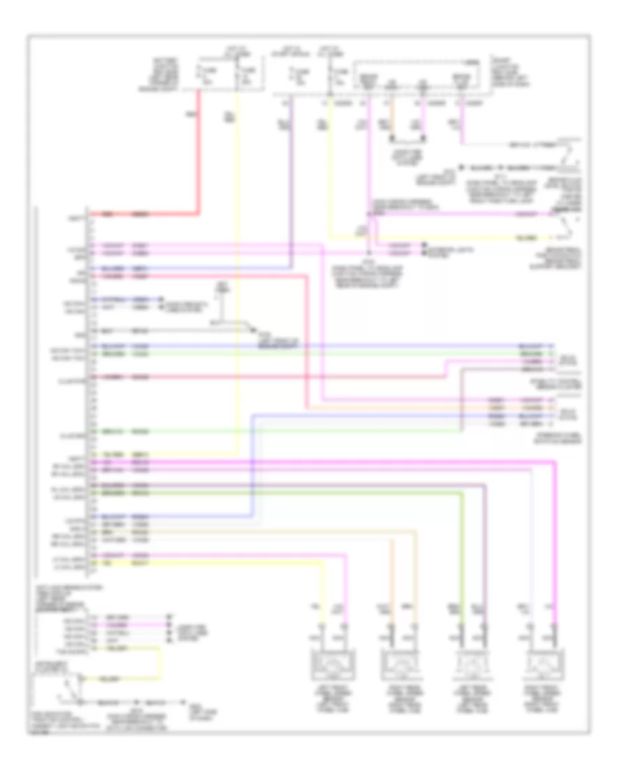
Anti-lock Brakes Wiring Diagram for Ford Focus SE 2010
List of elements for Anti-lock Brakes Wiring Diagram for Ford Focus SE 2010:
- (main wiring harness, near breakout to g203) s223
- (not used)
- Anti-lock brake system (abs) module (left rear corner of engine compartment)
- Battery junction box (bjb) (left rear corner of engine compt)
- Bpp
- Brake fluid level switch (top of master
- Brake fluid sw
- Brake pedal position switch (brake pedal support bracket)
- Brake pedal sw
- C2280b
- C2280d
- C2280f
- Cbp31
- Cca09
- Ccb08
- Ccs01
- Clus gnd
- Clus pwr
- Computer data lines system
- Cylinder reservoir)
- Data link connector)
- Exterior lights system
- Fuse 15a
- Fuse 20a
- Fuse 40a
- G101 (left front of engine compt)
- G102 (left front of engine compt)
- G203 (left side of dash)
- Gd122
- Gnd
- Hot at all times
- Hot in start or run
- Hs can yaw+
- Hs can yaw-
- Hs can+
- Hs can-
- Ign
- Instrument cluster (ic)
- Ivd rtn
- Ivd sig
- Left front wheel speed sensor (left front wheel hub)
- Left rear wheel speed sensor (left rear wheel hub)
- Lf whl spd+
- Lf whl spd-
- Logic
- Lr whl spd-
- Ms can+
- Ms can-
- Nca
- Near breakout to left front park/turn lamp)
- Near breakout to left rear of engine compt)
- Pad indicator/ traction control/ ambient lighting switch
- Rca09
- Rca17
- Rca18
- Rca19
- Rca20
- Rcs02
- Red
- Rf whl spd+
- Rf whl spd-
- Right front wheel speed sensor (right front wheel hub)
- Right rear wheel speed sensor (right rear wheel hub)
- Rl whl spd+
- Rr whl spd+
- Rr whl spd-
- S104 (dash panel to headlamp junction wiring harness,
- S111 (dash panel to headlamp junction wiring harness,
- S215 (main wiring harness, near breakout to
- Sas a
- Sas b
- Sbb09
- Sbb18
- Smart junction box (sjb) (behind left side of dash)
- Solid state
- Stability control sensor cluster
- Steering wheel rotation sensor
- Tcs on/off
- Vbatt
- Vca03
- Vca04
- Vca05
- Vca06
- Vca23
- Vca24
- Vcs06
- Vcs07
- Vdb04
- Vdb05
 Čeština
 Dansk
Dansk Deutsch
 Ελληνικά
 English
 English
 Suomi
Suomi Français
 Français
 עברית
עברית Hrvatski
 Magyar
 Italiano
 日本語
日本語 한국어
한국어 Nederlands
 Polski
 Português
 Português
 Română
 Русский
 Slovenčina
 Slovenščina
 Svenska
 Türkçe
 中文 (中国)
 Español