ANTI-LOCK BRAKES
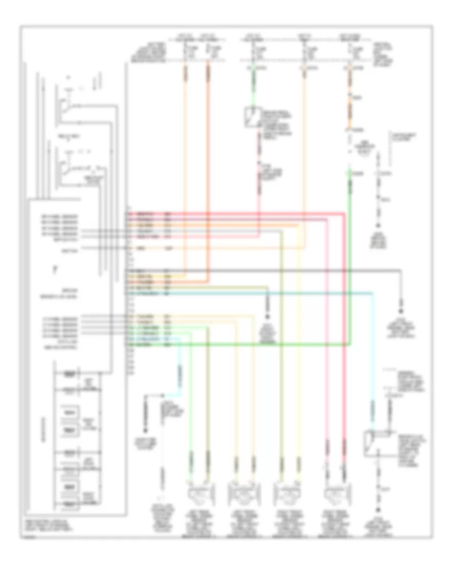
Anti-lock Brake Wiring Diagrams, with Traction Control for Ford Taurus SVG 2000
 https://portal-diagnostov.com/license.html
Automotive Electricians Portal FZCO
Automotive Electricians Portal FZCO
https://portal-diagnostov.com/license.html
https://portal-diagnostov.com/license.html
Automotive Electricians Portal FZCO
Automotive Electricians Portal FZCO
List of elements for Anti-lock Brake Wiring Diagrams, with Traction Control for Ford Taurus SVG 2000:
- Abs control module (left front of engine compt, below battery)
- Abs ind control
- Abs indicator
- Abs pump motor
- Battery junction box (front center of engine compt, behind radiator)
- Bpp switch
- Brake fluid level
- Brake fluid level switch (left rear of engine compt, to right of master cylinder)
- Brake pedal position (bpp) switch (under dash, upper front side of brake pedal)
- C201a
- C220a
- C220b
- C270a
- Central junction box (under left side of dash)
- Compt)
- Computer data lines system
- Data link
- Data link connector (mounted on dash, below steering column)
- Front
- Fuse 10a
- Fuse 15a
- Fuse 20a
- Fuse 40a
- G100 (left front fender, near battery junction box)
- G101 (front of right front fender)
- G206 (behind center of dash)
- Generic electronic module (gem) (under left side of dash)
- Ground
- Hot at all times
- Hot in run
- Hot in run or start
- Ignition
- Illum- ination
- Indicator tcs
- Instrument cluster
- Interior lights system
- Left dump valves
- Left front wheel speed sensor (in left front wheelwell, mounted on brake assembly)
- Left iso valves
- Left rear wheel speed sensor (in left rear wheelwell, mounted on brake assembly)
- Lf wheel sensor
- Lr wheel sensor
- Nca
- On/ off
- Rear
- Red/pnk
- Relay box
- Rf wheel sensor
- Right dump valves
- Right front wheel speed sensor (in right front wheelwell, mounted on brake assembly)
- Right iso valves
- Right rear wheel speed sensor (in right rear wheelwell, mounted on brake assembly)
- Rr wheel sensor
- S137
- S207
- S209
- S212
- S213 (under left side of dash)
- S217 (behind dash, near hvac unit)
- S218 (behind dash, near hvac unit)
- Solid state
- Tan/red
- Traction control off
- Traction control sw
- Traction control switch
- Traction ind control
Anti-lock Brake Wiring Diagrams, without Traction Control for Ford Taurus SVG 2000
List of elements for Anti-lock Brake Wiring Diagrams, without Traction Control for Ford Taurus SVG 2000:
- Abs control module (left front of engine compt, below battery)
- Abs ind control
- Abs indicator
- Abs pump motor
- Battery junction box (front center of engine compt, behind radiator)
- Bpp switch
- Brake fluid level
- Brake fluid level switch (left rear of engine compt, to right of master cylinder)
- Brake pedal position (bpp) switch (under dash, upper front side of brake pedal)
- C201a
- C220b
- C270a
- Central junction box (under left side of dash)
- Compt)
- Computer data lines system
- Data link
- Data link connector (mounted on dash, below steering column)
- Front
- Fuse 10a
- Fuse 15a
- Fuse 20a
- Fuse 40a
- G100 (left front fender, near battery junction box)
- G101 (front of right front fender)
- G206 (behind center of dash)
- Generic electronic module (gem) (under left side of dash)
- Ground
- Hot at all times
- Hot in run
- Hot in run or start
- Ignition
- Instrument cluster
- Left dump valves
- Left front wheel speed sensor (in left front wheelwell, mounted on brake assembly)
- Left iso valves
- Left rear wheel speed sensor (in left rear wheelwell, mounted on brake assembly)
- Lf wheel sensor
- Lr wheel sensor
- Nca
- Rear
- Red/pnk
- Relay box
- Rf wheel sensor
- Right dump valves
- Right front wheel speed sensor (in right front wheelwell, mounted on brake assembly)
- Right iso valves
- Right rear wheel speed sensor (in right rear wheelwell, mounted on brake assembly)
- Rr wheel sensor
- S137
- S209
- S212
- S213 (under left side of dash)
- Solid state
- Tan/red

 Čeština
 Dansk
Dansk Deutsch
 Ελληνικά
 English
 English
 Suomi
Suomi Français
 Français
 עברית
עברית Hrvatski
 Magyar
 Italiano
 日本語
日本語 한국어
한국어 Nederlands
 Polski
 Português
 Português
 Română
 Русский
 Slovenčina
 Slovenščina
 Svenska
 Türkçe
 中文 (中国)