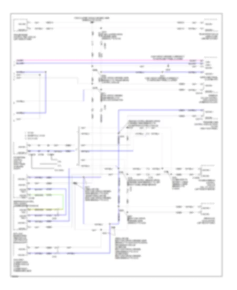
COMPUTER DATA LINES
Computer Data Lines Wiring Diagram (1 of 2) for Ford F-150 XLT 2013
 https://portal-diagnostov.com/license.html
Automotive Electricians Portal FZCO
Automotive Electricians Portal FZCO
https://portal-diagnostov.com/license.html
https://portal-diagnostov.com/license.html
Automotive Electricians Portal FZCO
Automotive Electricians Portal FZCO
List of elements for Computer Data Lines Wiring Diagram (1 of 2) for Ford F-150 XLT 2013:
- (body main wiring harness, near breakout to c311)
- (body main wiring harness, near breakout to g201)
- (engine control sensor wiring harness, near breakout to c214) (w/sync) s246
- (except super cab: body main wiring harness, near breakout to c312) (super cab: body main wiring harness, near breakout to c313)
- (main wiring harness) s261
- (main wiring harness) s262
- (main wiring harness, in breakout to hazard/pad/ traction switch) s235
- (main wiring harness, near breakout to c213) s219
- (main wiring harness, near breakout to mode select switch)
- (main wiring harness, near breakout to mode select switch) s232
- (main wiring harness, near breakout to passenger air bag module) s239
- (or vdb13)
- (or vdb14)
- (super cab: body main wiring harness, near breakout to c313) vdb14
- (w/ adjustable pedals) s212
- (w/ sony radio)
- Accessory protocol interface module (apim) (w/ sync) (center of dash)
- Audio control module (acm) (center of dash)
- Audio digital signal processing (dsp) module (w/ sony radio) (under center console)
- Automatic a/c
- Body control module (bcm) (right kick panel)
- C214
- C2280a
- C2280b
- C2280f
- C228a
- C2395
- C240a
- C248
- C290b
- C294a
- C300
- C312
- C3154a
- C3265c
- C3313b
- C341d
- Data link connector (dlc) (left side of dash)
- Datc hvac module
- Driver seat module (dsm) (w/ memory seats) (under driver's seat)
- Dual climate controlled seat module (dcsm) (w/ climate controlled seats) (under front passenger's seat)
- Emtc hvac module
- Except hmi
- Front controls interface module (fcim) (except hmi)
- Front controls interface module (fcim) (hmi)
- Front display interface module (fdim) (w/o navigation)
- Fuse 15a
- G202 (left side of dash)
- Gd133
- Global positioning system module (gpsm) (w/o navigation) (center of dash)
- Head up display (hud) module (w/ 4 inch display)
- Hot at all times
- Hs can +
- Hs can -
- I can +
- I can -
- Manual a/c
- Ms can +
- Ms can -
- Power running board (prb) module (w/ power running boards) (right rear of cab)
- S213
- S214 (main wiring harness, near breakout to g203)
- S218 (main wiring harness, near breakout to c213)
- S225
- S230 (main wiring harness, in breakout to instrument panel cluster)
- S231
- S233
- S245 (w/sync)
- S249
- S250 (main wiring harness, in breakout to autolamp/sunload sensor)
- S318
- S326
- S328
- S335
- Sbp24
- Tire pressure monitor module (right end of dash)
- Vdb04
- Vdb05
- Vdb06
- Vdb07
- Vdb13
- Vdb14
- W/ 8 inch display
- W/ touch screen 4 inch display
- W/ touch screen 8 inch display
- W/o touch screen & w/ touch screen 8 inch display
Computer Data Lines Wiring Diagram (2 of 2) for Ford F-150 XLT 2013
List of elements for Computer Data Lines Wiring Diagram (2 of 2) for Ford F-150 XLT 2013:
- (engine control sensor wiring harness, near breakout to powertrain control module) s102
- (main wiring harness, in breakout to instrument panel cluster)
- (regular cab: body main wiring harness, near breakout to audio digital signal processing module) (super cab: body main wiring harness, near breakout to c313) (super crew: body main wiring harness, near breakout to c312)
- (t-box jumper wiring harness, near breakout to c2108) s271
- 3.5l
- 3.7l
- 5.0l & 6.2l
- 6.2l w/ 4x2
- Anti-lock brake system (abs) module (left front of engine compt)
- Breakout to trailer brake control module)
- C1381b
- C139
- C1463b
- C1551b
- C175b
- C2108
- C212
- C215
- C2371a
- C2414a
- C248
- C310b
- C312
- Except 6.2l w/ 4x2
- Hs can +
- Hs can -
- Hs can yaw +
- Hs can yaw -
- Hsc1-a
- Hsc1-c
- Hsc2-a
- Hsc2-c
- I can +
- I can -
- Instrument panel cluster (ipc)
- Occupant classification system module (ocsm) (under front passenger's seat)
- Parking aid module (pam) (left end of dash)
- Power steering control module (3.5l, 3.7l & 5.0l) (left side of engine)
- Powertrain control module (right rear of engine compt)
- Restraints control module (rcm) (under center console)
- S100
- S130 (engine control sensor wiring harness, near breakout to left front wheel speed sensor)
- S131
- S152
- S153 (alternator to battery + cable assembly, near breakout to c1463a)
- S204
- S210
- S211 (main wiring harness, near breakout to data link connector)
- S216
- S217 (main wiring harness, in breakout to instrument panel cluster)
- S263
- S317 (regular cab: body main wiring harness, near breakout to g300) (except regular cab: body main wiring harness, near breakout to c313)
- S320
- S323
- S340
- Steering column control module (sccm) (steering column)
- Telematics module (crew chief) (center of dash)
- Trailer brake control (tbc) module (left side of dash)
- Transfer case control module (tccm) (w/ 4x4) (right kick panel)
- Vca23
- Vca24
- Vdb04
- Vdb05
- W/ 4x4

 Čeština
 Dansk
Dansk Deutsch
 Ελληνικά
 English
 English
 Suomi
Suomi Français
 Français
 עברית
עברית Hrvatski
 Magyar
 Italiano
 日本語
日本語 한국어
한국어 Nederlands
 Polski
 Português
 Português
 Română
 Русский
 Slovenčina
 Slovenščina
 Svenska
 Türkçe
 中文 (中国)