POWER DISTRIBUTION
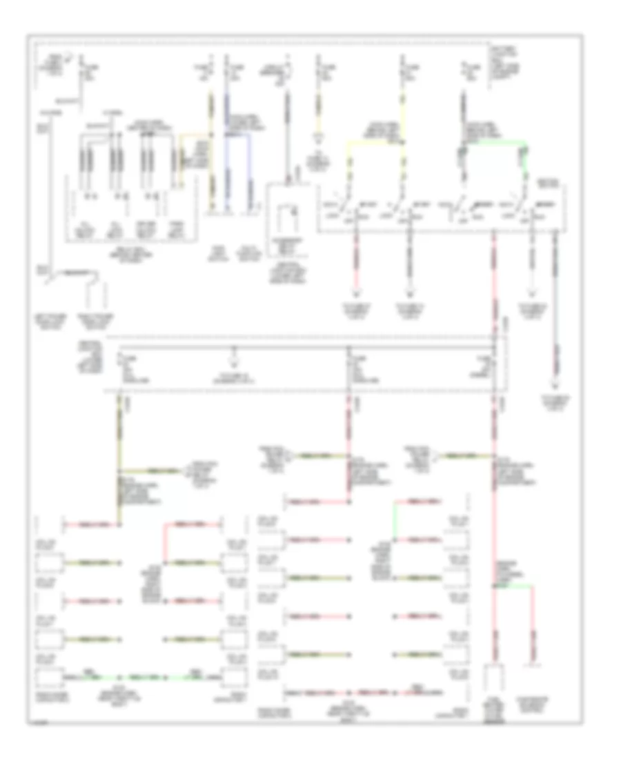
Power Distribution Wiring Diagram (1 of 4) for Ford Cab & Chassis F350 Super Duty 2001
 https://portal-diagnostov.com/license.html
Automotive Electricians Portal FZCO
Automotive Electricians Portal FZCO
https://portal-diagnostov.com/license.html
https://portal-diagnostov.com/license.html
Automotive Electricians Portal FZCO
Automotive Electricians Portal FZCO
List of elements for Power Distribution Wiring Diagram (1 of 4) for Ford Cab & Chassis F350 Super Duty 2001:
- (center of dash) g206
- (diesel only)
- (diesel w/o dual gen)
- (engine harn, left front of engine compt) s120
- (engne harn, near breakout to starter motor relay) s146
- (in back-up lamp harn, left rear of engine compt) s251
- (left rear of engine compt) bi-fuel relay module
- (left side of engine compt) battery junction box
- (main harn, lower center of dash) s223
- (main harn, near inst cluster breakout) s298
- A/c clutch relay
- Adjustable pedal switch
- Anti-lock brake system module
- Battery junction box (left side of engine compt)
- Bi-fuel
- Bi-fuel power relay
- Blower motor relay
- C104b
- C152
- C154
- C257a
- California
- Cold start heater relay
- Compuvalve module
- Daytime running lamps resistor
- Diesel
- Driver heated seat module
- Driver's seat regulator control switch
- Drl relay block (behind right side of dash)
- Except california
- Fog lamp relay
- From a fuse 23 (diagram 1 of 4)
- Fuel pump relay
- Fuse 10a
- Fuse 15a
- Fuse 20a
- Fuse 30a
- Fuse 3a
- Fuse 40a
- Fuse 5a (diesel w/ dual gen)
- Fuse 60a
- Gasoline
- Generator/ voltage regulator (diesel)
- Generator/ voltage regulator (gasoline)
- Generator/ voltage regulator (secondary: diesel w/ dual gen)
- Glow plug control module
- Glow plug relay
- High to low relay
- I/p relay block (behind left side of dash)
- Idm power relay (diesel)
- Left battery (diesel only)
- Low to high relay
- Manifold intake air heater relay
- Nca
- Passenger heated seat module
- Pcm diode
- Pcm power relay
- Power point
- Radio
- Red
- Right battery
- S147 (near starter motor relay)
- S148 (near starter motor relay)
- S149 (near starter motor relay)
- S290
- Starter motor
- Starter motor relay
- To fuse 17 (diagram 1 of 4)
- To fuse 26 (diagram 2 of 4)
- To fuse 30 (diagram 2 of 4)
- Trailer battery charge relay
- Trailer brakes feed (taped in harness)
- Trailer reversing lamps relay
- Trailer running lamps relay
- Trailer tow relay block (left side of engine compt)
- Transfer case shift relay
- Washer pump relay
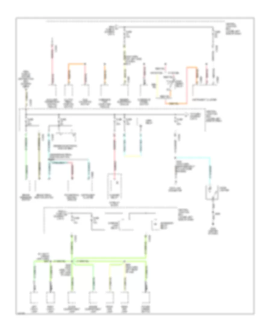
Power Distribution Wiring Diagram (2 of 4) for Ford Cab & Chassis F350 Super Duty 2001
List of elements for Power Distribution Wiring Diagram (2 of 4) for Ford Cab & Chassis F350 Super Duty 2001:
- (engine harn, pia diesel harn) s154
- (main harn, behind left side of dash) s210
- (main harn, behind left side of dash) s212
- (main harn, center of dash) s230
- (main harn, lower left side of dash) s214
- Acc
- Accessory delay relay
- All lock relay
- All unlock relay
- Battery junction box (left side of engine compt)
- C242a
- C242b
- Central junction box (lower left side of dash)
- Circuit breaker 30a
- Coil on plug 1
- Coil on plug 10
- Coil on plug 2
- Coil on plug 3
- Coil on plug 4
- Coil on plug 5
- Coil on plug 6
- Coil on plug 7
- Coil on plug 8
- Coil on plug 9
- Driver unlock relay
- From b fuse 4 (diagram 1 of 4)
- From pcm power relay (diagram 1 of 4)
- Fuel heater/ water in fuel sensor
- Fuse 15a
- Fuse 20a
- Fuse 30a
- Fuse 30a (5.4l gasoline)
- Fuse 30a (6.8l gasoline)
- Fuse 30a (diesel)
- Fuse 50a
- Ignition switch
- Left power door lock switch
- Lock
- Main light switch
- Multi- function switch
- Nca
- Off
- Park lamp relay
- Radio capacitor 1
- Radio noise capacitor 2
- Relay box (behind center of dash)
- Right power door lock switch
- Run
- S130 (engine harn, near throttle body)
- S135 (engine harn, right side of engine block)
- S179 (engine harn, left side of engine compartment)
- S272 (main harn, left side of dash)
- Start
- To fuse 10 (diagram 4 of 4)
- To fuse 13 (diagram 3 of 4)
- To fuse 19 (diagram 3 of 4)
- To fuse 20 (diagram 4 of 4)
- To fuse 22 (diagram 4 of 4)
- To fuse 27 (diagram 4 of 4)
- W/ rke
- W/o rke
- Wastegate solenoid control
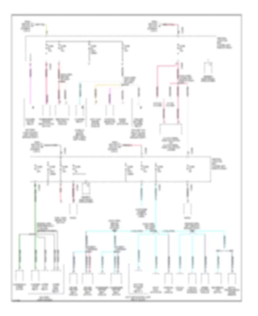
Power Distribution Wiring Diagram (3 of 4) for Ford Cab & Chassis F350 Super Duty 2001
List of elements for Power Distribution Wiring Diagram (3 of 4) for Ford Cab & Chassis F350 Super Duty 2001:
- (in vanity mirror lamp harn) s937
- (main harn, top left side of dash) s213
- (near brake pedal position switch) s221
- 87a
- Accessory delay relay
- Auxiliary powertrain control module
- Brake pedal position switch
- Brake pressure switch
- C240a
- C242a
- C242b
- C250a
- C250b
- Central junction box (lower left side of dash)
- Cigar lighter
- Clutch pedal position switch
- Dash reset relay
- Data link connector
- Engine compartment lamp
- Flasher relay
- From fuse 22 (power distribution box) (diagram 2 of 4)
- From fuse 3 k (diagram 3 of 4)
- From h fuse 30 (diagram 2 of 4)
- Front map lamp
- Fuse 10a
- Fuse 15a
- Fuse 20a
- Fuse 5a
- G206 (center of dash)
- Generic electronic module
- Generic electronic module (gem)
- Glove compartment lamp
- Horn relay
- I/p relay block
- Idle validation switch
- Instrument cluster
- Interior lamp relay
- Left vanity lamp
- Nca
- Overdrive cancel switch
- Overhead trip computer module
- Power mirror switch
- Powertrain control module
- Rear map lamp
- Right vanity lamp
- S229 (main harn, top left side of dash)
- S242 (main harn, near breakout to customer access)
- S290
- S906 (main harn, left rear of cab)
- To fuse 4 (diagram 3 of 4)
- W/ bi-fuel
- W/o bi-fuel
Power Distribution Wiring Diagram (4 of 4) for Ford Cab & Chassis F350 Super Duty 2001
List of elements for Power Distribution Wiring Diagram (4 of 4) for Ford Cab & Chassis F350 Super Duty 2001:
- (engine harn, left rear of engine compt) s124
- (engine harn, near breakout to power distribution box)
- (main harn, behind center of dash) s238
- (main harn, center of dash) s200
- (main harn, left side of dash) s206
- (main harn, left side of dash) s235
- (main harn, lower left side of dash) s275
- A/t
- Anti-lock brake system module
- Battery junction box
- Battery junction box (left side of engine compt)
- Blend door actuator
- Blower motor relay
- C242a
- C242b
- Central junction box (lower left side of dash)
- Clutch pedal position switch or clutch pedal position switch jumper
- Customer access (taped in harn)
- Daytime running lamp relay 2
- Daytime running lamp relay block
- Digital transmission range sensor
- Driver heated seat module
- Driver heated seat switch
- Flasher relay
- From ignition switch (diagram 2 of 4)
- Fuel tank selector switch
- Function selector switch
- Fuse (not used)
- Fuse 10a
- Fuse 15a
- Fuse 30a
- Fuse 5a
- Generic electronic module (gem)
- I/p relay block (behind dash, near inst panel)
- M/t
- Parking aid module
- Passenger heated seat module
- Passenger heated seat switch
- Passenger's air bag deactivation switch
- Radio
- Red
- Restraints control module
- Reversing lamp switch
- S119
- S334
- S335
- Shift lock actuator
- Speed control module
- Tan/red
- Trailer battery charge relay
- Trailer tow relay block (left side of engine compt)
- Vacuum hublock solenoid
- Vacuum pump
- W/ c/d player
- W/o c/d player
- Washer pump relay
- Windshield wiper motor
- Wiper hi/lo relay
- Wiper run/ park relay

 Čeština
 Dansk
Dansk Deutsch
 Ελληνικά
 English
 English
 Suomi
Suomi Français
 Français
 עברית
עברית Hrvatski
 Magyar
 Italiano
 日本語
日本語 한국어
한국어 Nederlands
 Polski
 Português
 Português
 Română
 Русский
 Slovenčina
 Slovenščina
 Svenska
 Türkçe
 中文 (中国)