POWER DISTRIBUTION
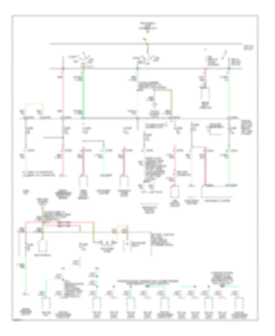
Power Distribution Wiring Diagram (1 of 4) for Ford Explorer 2005
 https://portal-diagnostov.com/license.html
Automotive Electricians Portal FZCO
Automotive Electricians Portal FZCO
https://portal-diagnostov.com/license.html
https://portal-diagnostov.com/license.html
Automotive Electricians Portal FZCO
Automotive Electricians Portal FZCO
List of elements for Power Distribution Wiring Diagram (1 of 4) for Ford Explorer 2005:
- (diagram 3 of 4)
- (in dash panel to engine harness, near breakout to right side of engine compt)
- (in window regulator jumper assembly, near breakout to c3134) s313
- (left side of engine compt, at fender apron) battery junction box (bjb)
- Abs control module
- Adjustable pedal switch
- Auxiliary a/c relay
- Auxiliary junction box (ajb)
- Battery
- Battery junction box (bjb) (left side of engine compartment, at fender apron)
- Battery junction box (bjb) (left side of engine compt, at fender apron)
- Blower motor relay
- C1035a
- C1035b
- C175b
- C205a
- C270c
- C3203e
- Central junction box (cjb) (behind left side of dash)
- Circuit breaker 30a
- Console 1 power point (in center console)
- Console 2 power point (in center console)
- Daytime running lamps (drl) module
- Engine compartment relay box (at right side of engine compartment)
- From b fuse 6 (bjb) (diagram 1 of 4)
- From fuse 8 (bjb) (diagram 1 of 4)
- Fuel pump relay
- Fuse 10a
- Fuse 15a
- Fuse 20a
- Fuse 30a
- Fuse 40a
- Fuse 50a
- Fuse 5a
- Fuse 60a
- G200 (at right ``a'' pillar)
- Generator
- Harness, near breakout to joint connector 1) s170
- Horn relay
- Ignition relay
- Left turn trailer tow relay
- Main light switch
- Nca
- Parking lamp trailer tow relay
- Pcm power relay
- Powertrain control module (pcm)
- Rear auxiliary junction box (ajb) (at right ``d" pillar)
- Rear window defrost relay
- Rear wiper motor assembly
- Red
- Regulator jumper assembly, near breakout to g401) s412
- Reversing lamp trailer tow relay
- Right power seat switch
- Right turn trailer tow relay
- S116
- S119
- S143 (at battery cable assembly, near breakout to battery junction box)
- S216
- Starter motor
- Starter relay
- Tan/ (in main harness, near breakout to central junction box) s259
- To accessory delay relay (cjb) (diagram 3 of 4)
- To fuse 10 (cjb)
- To fuse 11 (bjb) (diagram 1 of 4)
- To fuse 15 (bjb) (diagram 3 of 4)
- To fuse 16 (cjb) (diagram 4 of 4)
- To fuse 26 (bjb) (diagram 1 of 4)
- To fuse 5 (cjb) (diagram 3 of 4)
- To ignition switch (diagram 2 of 4)
- Trailer electronic brake control module
- Trailer tow battery charge relay
- Transfer case high to low relay
- Transfer case low to high relay
- Vehicle security module (vsm)
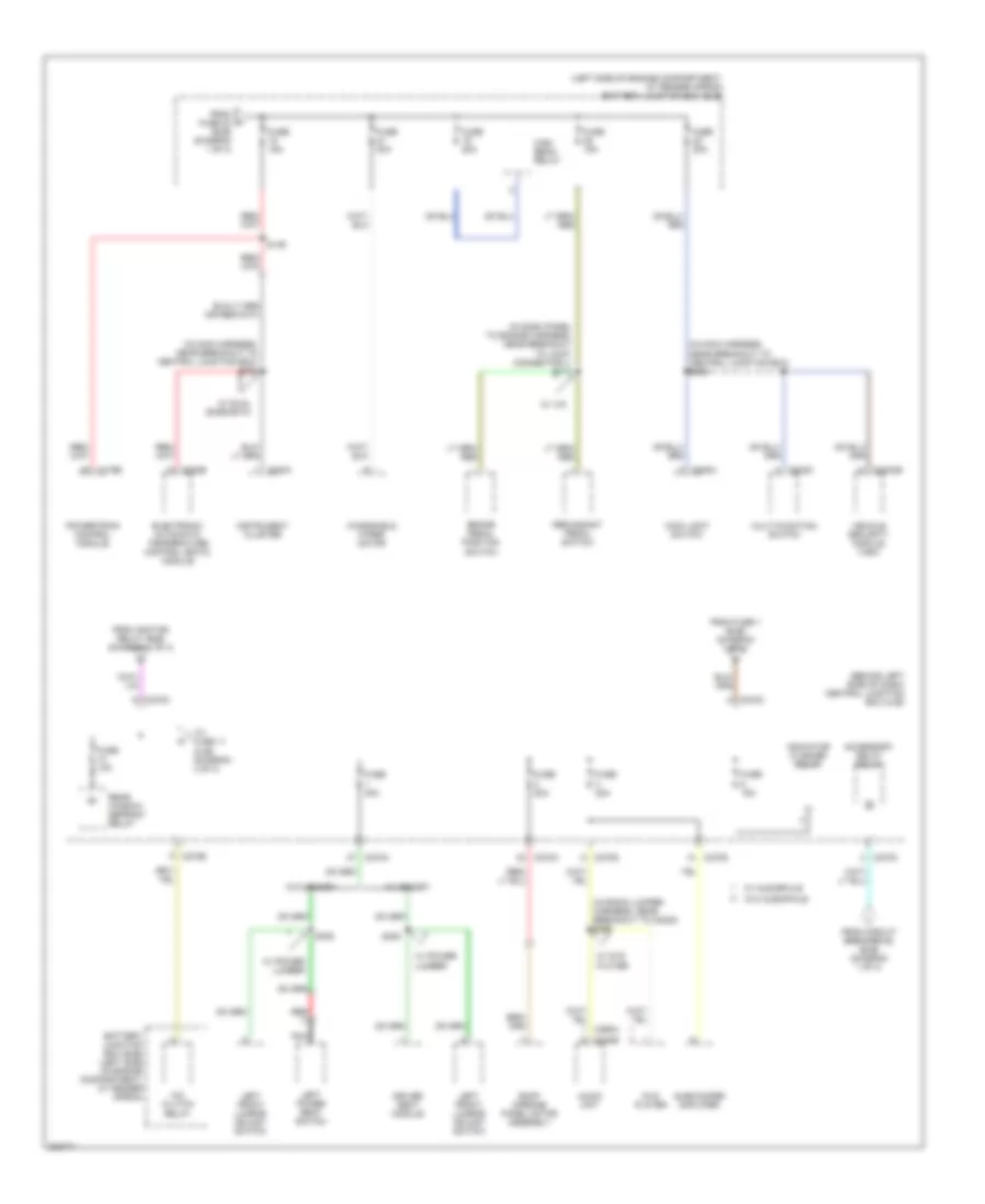
Power Distribution Wiring Diagram (2 of 4) for Ford Explorer 2005
List of elements for Power Distribution Wiring Diagram (2 of 4) for Ford Explorer 2005:
- (diagram 4 of 4)
- (in engine control sensor & fuel charge harness, near breakout to fuel injector 4) s107
- (in engine control sensor & fuel charge harness, near breakout to fuel injector 7) s109
- (in main harness, near breakout to central junction box) s207
- (w/ audiophile)
- (w/o audiophile)
- 4.0l
- 4.6l
- Abs control module
- Abs test connector
- Acc
- Audio unit
- Battery junction box (bjb) (left side of engine compt, at fender apron)
- Brake pressure switch
- Brake shift interlock
- Breakout to ignition coil)
- C220a
- C220b
- C240b
- C270a
- C270b
- C270d
- C270e
- C270f
- C270g
- C270h
- C290a
- C310a
- Central junction box (cjb) (behind left side of dash)
- Coil on plug (cop) 1
- Coil on plug (cop) 2
- Coil on plug (cop) 3
- Coil on plug (cop) 4
- Coil on plug (cop) 5
- Coil on plug (cop) 6
- Coil on plug (cop) 7
- Coil on plug (cop) 8
- Connector 1) s113
- Digital digital transmission transmission range (dtr) sensor
- Electronic compass
- From fuse 23 (bjb) (diagram 1 of 4)
- From s207 (diagram 2 of 4)
- Fuse 10a
- Fuse 15a
- Fuse 2a
- Fuse 5a
- Ignition coil
- Ignition relay
- Ignition switch
- Ignition transformer capacitor
- Ignition transformer capacitor 1
- Ignition transformer capacitor 2
- Indicator flasher relay
- Instrument cluster
- Key in ignition switch
- Key removal inhibit solenoid
- Lock
- Nca
- Off
- Pcm power diode
- Pcm power relay
- Rear wiper motor assembly
- Red
- Restraints control module
- Run
- Start
- To fuse 25 (cjb) j
- To s113 (diagram 2 of 4)
- Windshield wiper motor
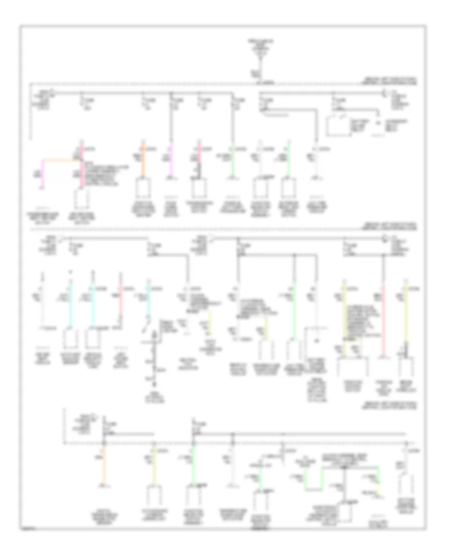
Power Distribution Wiring Diagram (3 of 4) for Ford Explorer 2005
List of elements for Power Distribution Wiring Diagram (3 of 4) for Ford Explorer 2005:
- (behind left side of dash) central junction box (cjb)
- (in dash panel to engine harness, near breakout to joint connector 1) s171
- (in main harness, near breakout to central junction box) s205
- (in main harness, near breakout to central junction box) s232
- (in radio jumper harness, near breakout to c2238) s266
- (left side of engine compartment, at fender apron) battery junction box (bjb)
- A/c clutch relay
- Accessory delay relay
- Audio unit
- Battery junction box (bjb) (left side of engine compartment, at fender apron)
- Brake pedal position switch
- C175b
- C202c
- C205a
- C220a
- C228b
- C240b
- C270a
- C270b
- C270c
- C270d
- C270g
- C3203e
- Driver seat module
- Dvd player
- Electronic automatic temperature control (eatc) module
- From circuit breaker 62 (bjb) (diagram 1 of 4)
- From fuse 1 (bjb) (diagram 1 of 4)
- From fuse 23 (bjb) (diagram 1 of 4)
- From ignition relay (bjb) (diagram 1 of 4)
- Fuse 10a
- Fuse 15a
- Fuse 20a
- Fuse 30a
- High beam relay
- Indicator flasher relay
- Instrument cluster
- Left front lumbar adjust switch
- Left power seat switch
- Main light switch
- Multi-function switch
- Nca
- Powertrain control module
- Rear window defrost relay
- Red
- Redundant pedal switch
- Roof opening panel motor assembly
- S149
- S305
- Subwoofer amplifier
- To fuse 11 (cjb) (diagram 4 of 4)
- Vehicle security module (vsm)
- W/ audiophile
- W/ dual zone eatc
- W/ dvd player
- W/ ivd
- W/ memory
- W/ power lumber
- W/o audiophile
- W/o memory
- Windshield wiper motor
Power Distribution Wiring Diagram (4 of 4) for Ford Explorer 2005
List of elements for Power Distribution Wiring Diagram (4 of 4) for Ford Explorer 2005:
- (behind left side of dash) central junction box (cjb)
- (in main harness, near breakout to central junction box) s247
- (in rear axle shifter motor control switch extension harness, in breakout to traction control switch) s264
- Accessory delay relay
- Auto-dimming interior mirror unit
- Autolamp/ sunload sensor
- Auxiliary a/c relay
- Battery charge trailer tow relay
- Battery saver relay
- Brake shift interlock
- C228b
- C270a
- C270b
- C270c
- C270d
- C270e
- C270f
- C270g
- C270h
- C294a
- C294b
- C3203e
- C341g
- C938a
- Data link connector (dlc)
- Daytime running lamps (drl) module
- Digital transmission range (dtr) sensor
- Driver seat module
- Driver side seat heater switch
- Electronic automatic temperature control (eatc) module
- Exterior rear view mirror switch
- Four- wheel drive switch
- From fuse 10 (cjb) (diagram 3 of 4)
- From fuse 17 (cjb) (diagram 4 of 4)
- From fuse 22 (cjb) (diagram 2 of 4)
- From fuse 26 (cjb) (diagram 4 of 4)
- From fuse 29 (bjb) (diagram 1 of 4)
- Front cigar lighter
- Function selector switch assembly
- Fuse 15a
- Fuse 20a
- Fuse 5a
- Fuse 7.5a
- G200 (at right ``a" pillar)
- Harness, near breakout to c2126) s263
- Left power seat switch
- Low tire pressure module
- Nca
- Neutral tow indicator
- Parking aid module (pam)
- Passenger side seat heater switch
- Passive anti-theft transceiver
- Positive crankcase ventilation heater
- Rear a/c control module
- Rear auxiliary junction box (ajb) (at right ``d" pillar)
- Red
- S216
- Temperature blend door actuator
- To fuse 20 (cjb) (diagram 4 of 4)
- To fuse 27 (cjb) (diagram 4 of 4)
- Traction control switch
- Transmission control switch
- Vehicle security module (vsm)
- W/ dual zone eatc
- W/ manual a/c

 Čeština
 Dansk
Dansk Deutsch
 Ελληνικά
 English
 English
 Suomi
Suomi Français
 Français
 עברית
עברית Hrvatski
 Magyar
 Italiano
 日本語
日本語 한국어
한국어 Nederlands
 Polski
 Português
 Português
 Română
 Русский
 Slovenčina
 Slovenščina
 Svenska
 Türkçe
 中文 (中国)