SUPPLEMENTAL RESTRAINTS
Supplemental Restraints Wiring Diagram for Ford Cutaway E250 2008
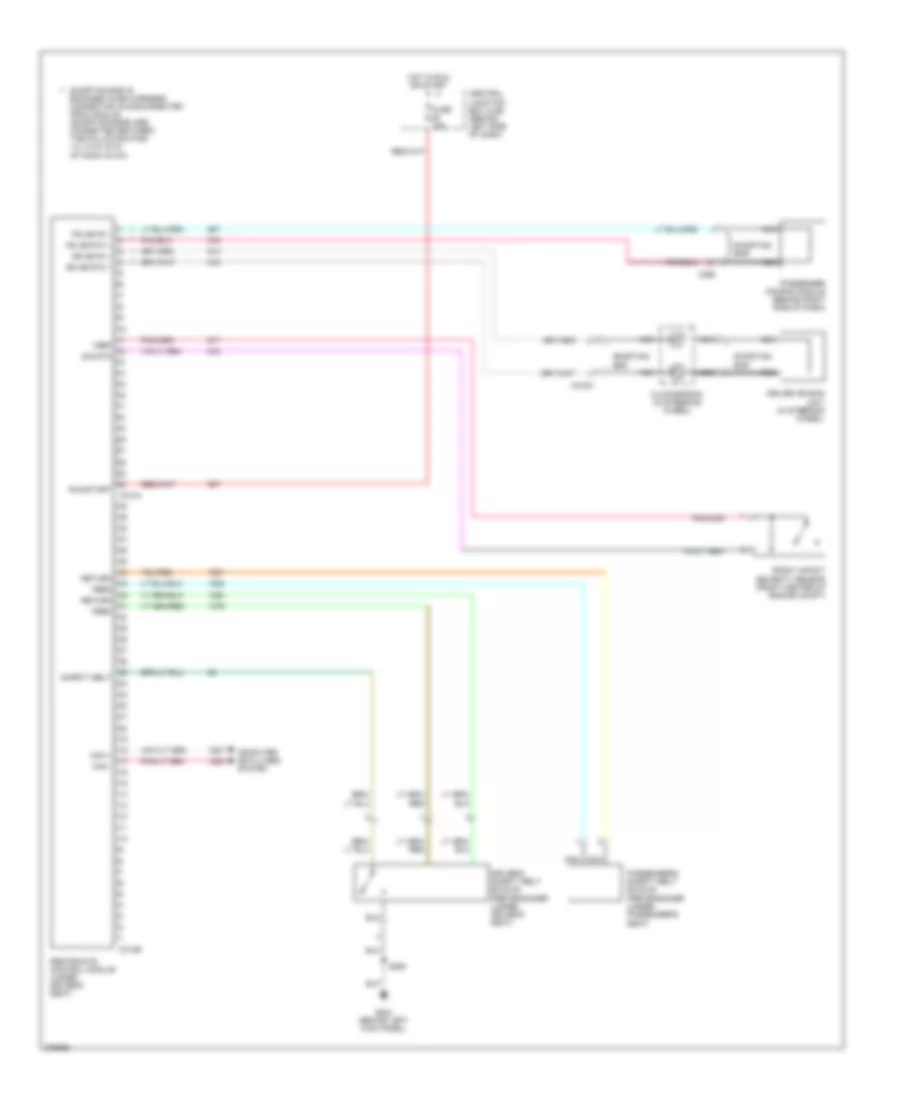
List of elements for Supplemental Restraints Wiring Diagram for Ford Cutaway E250 2008:
- C218a
- C256
- C310a
- C310b
- Can +
- Can -
- Central junction box (cjb) (behind left side of dash)
- Clockspring (in steering wheel)
- Computer data lines system
- Dr ab fd 1
- Dr ab rtn 1
- Driver air bag unit (in steering wheel)
- Driver's safety belt buckle pretensioner (under driver's seat)
- Feed
- Front impact severity sensor (front center of engine compt)
- Fuse 10a
- G204 (behind left kick panel)
- Hot in run or start
- Nca
- Passenger air bag module (behind right side of dash)
- Passenger's safety belt buckle pretensioner (under passenger's seat)
- Ps ab fd 1
- Ps ab rtn 1
- Restraints control module (under driver's seat)
- Return
- Run/start
- S250
- Safety belt
- Shorting bar
- Shorting bar is engaged when harness connector is disconnected from module (shorting bars are connected between the following pins: 1-2, 3-4 & 15-16 of conn c310a)
- Vref sig rtn
 Čeština
 Dansk
Dansk Deutsch
 Ελληνικά
 English
 English
 Suomi
Suomi Français
 Français
 עברית
עברית Hrvatski
 Magyar
 Italiano
 日本語
日本語 한국어
한국어 Nederlands
 Polski
 Português
 Português
 Română
 Русский
 Slovenčina
 Slovenščina
 Svenska
 Türkçe
 中文 (中国)
 Español