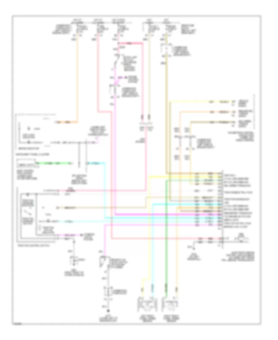
ANTI-LOCK BRAKES
Anti-lock Brake Wiring Diagrams for GMC Envoy XL 2002
List of elements for Anti-lock Brake Wiring Diagrams for GMC Envoy XL 2002:
- (under left side of dash) data link connector (dlc)
- Abs fuse 33 60a
- Abs pump
- Anti-lock indicator
- Auto a/c
- B10
- B7 b6
- Body control module (bcm) (under dash, on heater case)
- Brake fluid level switch (on master cylinder)
- Brake fluid lvl sig
- Brake fuse 51 10a
- Brake indicator
- C11
- Cruise control system
- Delivered torque sig
- Delivered torque signal
- Electronic brake control module (ebcm) (on inner left frame rail, beside transmission)
- G107 (lower left of engine block)
- G201 (right front of lower console)
- G304 (on left frame rail)
- Hot at all times
- Hot in run
- Hot in run or start
- Hvac 1 fuse 39 10a
- Ign e fuse 22 10a
- Ignition 3
- Instrument panel cluster
- Interior lights system
- Ipc/dci fuse 24 10a
- Left front wheel speed sensor
- Lf whl spd sens ref
- Lf whl spd sens sig
- Man a/c
- Pnk
- Powertrain control module (pcm) (upper left side of engine)
- Rear fuse block (below left rear seat)
- Red
- Requested torque sig
- Requested torque signal
- Rf whl spd sens ref
- Rf whl spd sens sig
- Right front wheel speed sensor
- S239
- Serial data
- Sp201
- Splice pack sp205 (behind left side of dash)
- Stop lamp switch (on brake pedal support bracket)
- Tan
- Tcc brake switch sig
- Trac active telltale
- Trac disable telltale
- Traction active indicator
- Traction control switch
- Traction disable sw
- Traction disabled indicator
- Traction disabled switch
- Underhood fuse block
- Underhood fuse block (left side of engine compt)
- Vehicle speed signal
- Vss
 Čeština
 Dansk
Dansk Deutsch
 Ελληνικά
 English
 English
 Suomi
Suomi Français
 Français
 עברית
עברית Hrvatski
 Magyar
 Italiano
 日本語
日本語 한국어
한국어 Nederlands
 Polski
 Português
 Português
 Română
 Русский
 Slovenčina
 Slovenščina
 Svenska
 Türkçe
 中文 (中国)
 Español