POWER DISTRIBUTION
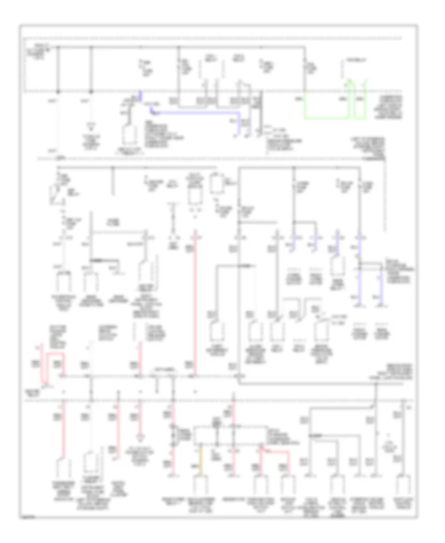
Power Distribution Wiring Diagram (1 of 4) for Pontiac Vibe GT 2006
 https://portal-diagnostov.com/license.html
Automotive Electricians Portal FZCO
Automotive Electricians Portal FZCO
https://portal-diagnostov.com/license.html
https://portal-diagnostov.com/license.html
Automotive Electricians Portal FZCO
Automotive Electricians Portal FZCO
List of elements for Power Distribution Wiring Diagram (1 of 4) for Pontiac Vibe GT 2006:
- (not used)
- Air pump fuse 50a
- Air pump relay (1.8l (vin l))
- Alt fuse 100a
- Alt s fuse 5a
- Am 2 fuse 15a
- Amp fuse 30a
- Battery
- C13
- Cd changer
- Digital radio receiver
- Dome fuse 15a
- Efi fuse 15a
- Efi relay
- Etc s fuse 10a
- Flasher relay
- From head main a
- Front dome lamp
- Fuse (diagram 1 of 4)
- Generator
- Hazard fuse 10a
- Head main fuse 30a
- Head relay
- Horn fuse 10a
- Horn relay
- Instrument panel cluster
- Instrument panel fuse block (left of steering column, behind storage compt)
- Keyless entry module
- Left instrument panel junction block (behind left side of dash)
- Main fuse 30a
- Map lamp
- Mayday onstar fuse 10a
- Module (vcim)
- Nca
- Powertrain control module (pcm)
- Powertrain control module (pcm) (1.8l (vin 8), fwd)
- Radio
- Radio amplifier
- Rear dome lamp
- Red
- S234
- S300
- St relay
- Starter
- Sunroof switch
- To abs 2 fuse (diagram 2 of 4)
- To horn fuse (diagram 1 of 4)
- To ignition switch (diagram 4 of 4)
- Underhood fuse block (left side of engine compt, mounted to inner fender)
- Vehicle communication interface
- Vehicle interface unit (viu)
- W/ sunroof
- W/o sunroof
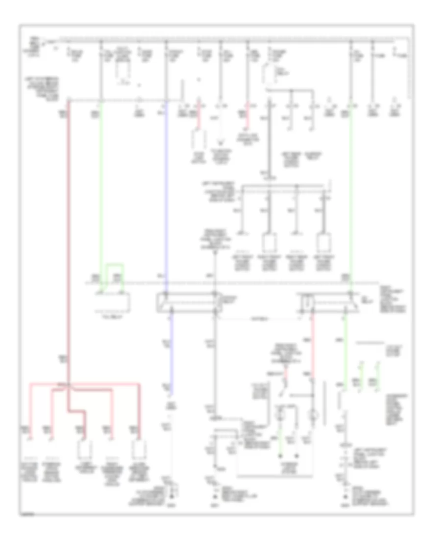
Power Distribution Wiring Diagram (2 of 4) for Pontiac Vibe GT 2006
List of elements for Power Distribution Wiring Diagram (2 of 4) for Pontiac Vibe GT 2006:
- (1.8l (vin l) & awd)
- (behind right side of dash) right instrument panel junction block
- (diagram 1 of 4)
- (left of steering column, behind storage compt) instrument panel fuse block
- (not used)
- Abs 1 fuse 30a
- Abs cut off relay
- Abs fuse 40a
- Abs underhood fuse block (attached to lf strut tower, near underhood fuse block)
- Ac/fresh/ recir- culation switch
- Backup lamp switch (m/t)
- Brake pressure modulator valve (bpmv)
- C12
- C13
- Cruise control module
- Cruise control release switch
- Daytime running lamps (drl) control module
- Def fuse 30a
- Def i/up fuse 10a
- Def relay
- Ecu-ig fuse 10a
- Fan 1 relay
- Fan 2 relay
- Flasher relay
- Fog fuse 15a
- Fog relay
- From alt fuse b
- Front washer motor
- Front wiper motor
- Gauge fuse 10a
- Generator
- Glass breakage sensor (w/ theft deterent)
- Heater fuse 40a
- Heater relay
- Ig 1 relay
- Instru- ment panel cluster
- Instrument panel fuse block (left of steering column, behind storage compt)
- Multi- function alarm module
- Noise filter
- P/w relay
- Park/neutral position (pnp) switch (a/t)
- Passenger seat belt/ airbag on/off indicator
- Powertrain control module (pcm)
- Rdi fan fuse 40a
- Rear defogger
- Rear defogger noise filter
- Rear washer motor
- Rear wiper diode
- Rear wiper relay 1
- Right instrument panel junction block (behind right side of dash)
- Rr wip fuse 15a
- S122
- S230
- S302
- Shiftlock control module
- Sp107 (in engine accessory harn, near pcm)
- Sp109 (in engine main harness, inside underhood fuse block)
- Steering angle sensor (w/ vsc)
- Theft deterrent module
- To 115 volt power outlet switch (diagram 3 of 4)
- To ecu b fuse (diagram 3 of 4)
- Underhood fuse block (left side of engine compt, mounted to inner fender)
- Vehicle speed sensor (vss) (1.8l (vin 8), 2wd, w/ vsc)
- Vehicle stability control (vsc) buzzer
- W/ vsc
- W/o vsc
- Wash fuse 15a
- Wiper fuse 25a
- Wiper/ washer switch
- Yaw & lateral acceleration sensor (w/ vsc)
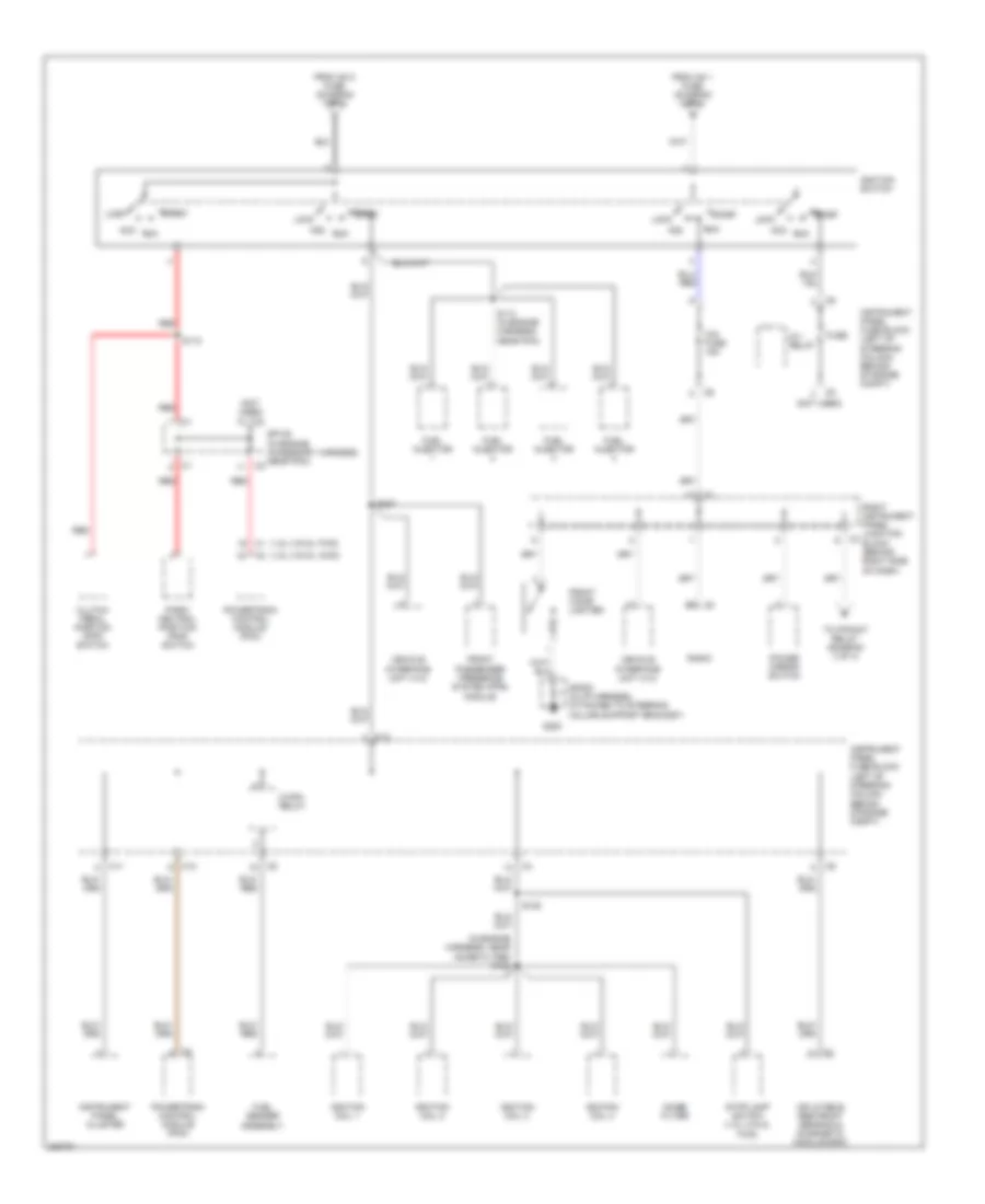
Power Distribution Wiring Diagram (3 of 4) for Pontiac Vibe GT 2006
List of elements for Power Distribution Wiring Diagram (3 of 4) for Pontiac Vibe GT 2006:
- (left of steering column, behind storage compt) instrument panel fuse block
- (not used)
- 115 volt power outlet
- 115 volt power outlet switch
- Accessory ac/dc power control module (under driver's seat)
- Am 1 fuse 25a
- C10
- Data link connector (dlc)
- Daytime running lamps control module
- Door fuse 25a
- Ecu-b fuse 10a
- From abs 2 d fuse (diagram 2 of 4)
- From right instrument panel junction block (diagram 2 of 4)
- From right instrument panel junction block (diagram 4 of 4)
- Front passenger presence system (pps) module
- Fuse
- G200
- G201
- Glass breakage sensor (w/ theft deterent)
- Illum lamp
- Interior lights system
- Inv fuse 15a
- Inv relay
- Left front power window switch
- Left instrument panel junction block (behind left side of dash)
- Left rear power window switch
- Multi- function alarm module
- Obd fuse 7.5a
- P/point fuse 15a
- P/point relay
- P/w relay
- Power fuse 30a
- Red
- Right front power window switch
- Right instrument panel junction block (behind right side of dash)
- Right rear power window switch
- S121
- S222
- Sp200 (in i/p harness, attached to steering column support bracket)
- Sp201 (behind right body hinge pillar trim panel)
- Steering angle sensor (actice handling)
- Stop fuse 15a
- Stop lamp switch
- Sunroof relay
- Tail fuse 15a
- Tail relay
- Theft deterrent module
- To ignition switch (diagram 4 of 4)
Power Distribution Wiring Diagram (4 of 4) for Pontiac Vibe GT 2006
List of elements for Power Distribution Wiring Diagram (4 of 4) for Pontiac Vibe GT 2006:
- (1.8l (vin 8), awd) c2
- (1.8l (vin 8), fwd) c1
- (in engine harness, near noise filter) s106
- (not used)
- Acc
- C/opn relay
- C1 b2
- C11
- C12
- Cig fuse 15a
- Clutch pedal position (cpp) switch
- From am 1 fuse (diagram 3 of 4)
- From am 2 fuse (diagram 1 of 4)
- Front cigar lighter
- Front passenger presence system (pps) module
- Fuel injector
- Fuel sender assembly
- Fuse
- G200
- Ig 1 relay
- Ignition coil 1
- Ignition coil 2
- Ignition coil 3
- Ignition coil 4
- Ignition switch
- Inflatable restraint sensing & diagnostic module (sdm)
- Instrument panel cluster
- Instrument panel fuse block (left of steering column, behind storage compt)
- Lock
- Noise filter
- Park/ neutral position (pnp) switch
- Power mirror switch
- Powertrain control module (pcm)
- Radio
- Red
- Right instrument panel junction block (behind right side of dash)
- Run
- S110
- S114 (in engine harness, near pcm)
- S125
- S237
- Sp108 (in engine accessory harness, near pcm)
- Sp200 (in i/p harness, attached to steering column support bracket)
- Start
- Stop lamp switch (1.8l (vin 8), fwd)
- To p/point relay (diagram 3 of 4)
- Vehicle interface unit (viu)

 Čeština
 Dansk
Dansk Deutsch
 Ελληνικά
 English
 English
 Suomi
Suomi Français
 Français
 עברית
עברית Hrvatski
 Magyar
 Italiano
 日本語
日本語 한국어
한국어 Nederlands
 Polski
 Português
 Português
 Română
 Русский
 Slovenčina
 Slovenščina
 Svenska
 Türkçe
 中文 (中国)