TRANSMISSION
5.7L
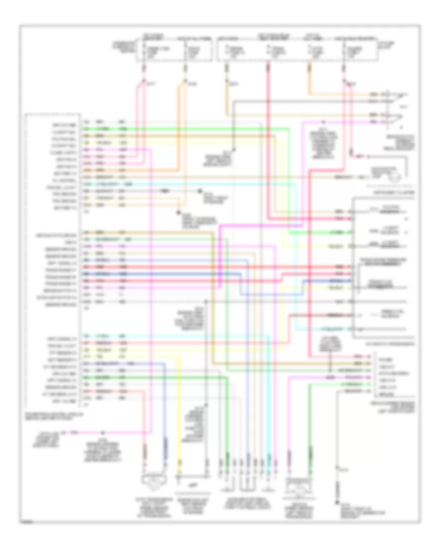
5.7L (VIN R), Transmission Wiring Diagram, 4L80-E for GMC Vandura G3500 1996
 https://portal-diagnostov.com/license.html
Automotive Electricians Portal FZCO
Automotive Electricians Portal FZCO
https://portal-diagnostov.com/license.html
https://portal-diagnostov.com/license.html
Automotive Electricians Portal FZCO
Automotive Electricians Portal FZCO
List of elements for 5.7L (VIN R), Transmission Wiring Diagram, 4L80-E for GMC Vandura G3500 1996:
- 1-2 shift
- 1-2 shift sol
- 2-3 shift sol
- 2-3 shift solenoid
- 5v reference
- A/t iss hi in
- A/t iss lo in
- Auto transmission input shaft speed sensor (inside front of transmission)
- Automatic transmission
- B17
- Battery in
- Brake fuse 18 10a
- Brake switch assembly (on brake pedal bracket)
- Brake switch input
- Data class ii
- Data link connector (under left side of dash)
- Ecm 1 fuse 20a
- Ecm b fuse 20a
- Ect sens input
- Eng 1 fuse 20a
- Engine coolant temp sensor (left side or top front of engine)
- G119 (right front of engine, on generator bracket)
- Gauges fuse 4 10a
- Hot at all times
- Hot in run
- Hot in run or start
- Hot in run, start or off
- I/p fuse block
- Ignition in
- Instrument cluster
- Malfunction indicator lamp
- Mil control
- Pcm ground
- Pcs sol hi out
- Pcs sol lo out
- Pnk
- Press ctrl
- Range signal "a"
- Range signal "b"
- Range signal "c"
- Red
- S102
- S113 (engine harn, left rear of engine compt)
- S120
- S124 or 136 (5.0l/5.7l: engine harness, 11 cm from maf sensor break-out; 7.4l: 7 cm from knock sensor break-out)
- S130
- S132
- S139 (5.0l/5.7l: engine harness, 4 cm from ect sensor break-out; 7.4l: eng harness, 21 cm from maf sensor break-out)
- S207 (i/p harness, 4 cm from tcc/brake lamp switch break-out)
- S210
- S216
- Sensor ground
- Sensor return
- Solenoid
- Tcc pwm
- Tcc pwm sol
- Throttle position sensor (mounted to side of throttle body)
- Tp sens input
- Trans fluid temp sensor
- Trans fuse 20 10a
- Trans range pressure switch assembly
- Trans temp sig in
- Underhood fuse/relay center
- Vehicle control module (vcm) (engine compt, left front fender apron)
- Vehicle speed sensor (left rear of transmission)
- Vss hi
- Vss lo
6.5L
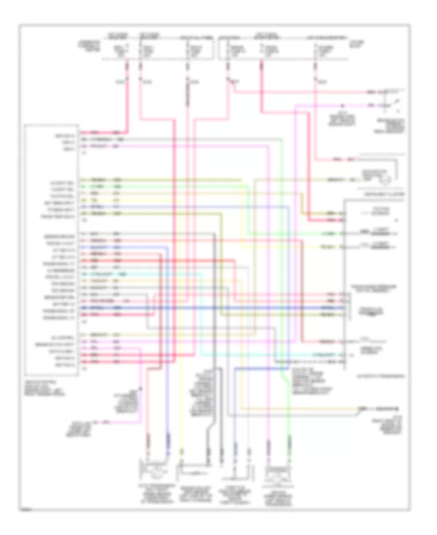
6.5L (VIN F), Transmission Wiring Diagram for GMC Vandura G3500 1996
List of elements for 6.5L (VIN F), Transmission Wiring Diagram for GMC Vandura G3500 1996:
- (i/p harn, 10 cm from radio harn break-out)
- 1-2 shift
- 1-2 shift sol
- 2-3 shift sol
- 2-3 shift solenoid
- 4k pulse signal
- A/t iss sens hi in
- A/t iss sens lo in
- A12
- Accelerator pedal position (app) module (throttle pedal mount)
- App 1 5v ref
- App 1 signal in
- App 2 5v ref
- App 2 signal in
- App 3 5v ref
- App 3 signal in
- Auto transmission input shaft speed sensor (inside front of transmission)
- Automatic transmission
- B10
- B12
- B17
- Battery in
- Brake fuse 18 10a
- Brake switch assembly (on brake pedal bracket)
- Brake switch in
- C11
- C12
- C13
- C14
- C15
- Class ii data
- D11
- D12
- D13
- Data link connector (under left side of dash)
- Diesel fuel fuse 20a
- Ecm b fuse 20a
- Ect sensor in
- Engine coolant temp sensor (top front of engine)
- G119 (right front of engine)
- G119 (right front of engine, on generator bracket)
- G125 (front of engine, near thermostat housing)
- Gauges fuse 4 10a
- Ground
- Hot at all times
- Hot in run
- Hot in run or start
- Hot in run, bulb test or start
- I/p fuse block
- Ignition in
- Instrument cluster
- Malfunction indicator lamp
- Mil control
- Pcm ground
- Pcs sol hi out
- Pcs sol lo out
- Pnk
- Power
- Powertrain control module (behind center of dash)
- Press ctrl
- Red
- S102
- S111 (engine harn, 4 cm from main harness to underhood fuse/relay center break-out)
- S112
- S114 (engine harn, left rear of engine compt)
- S115 (engine harness, 6 cm from fuel injection pump encoder break-out)
- S117
- S120
- S124 (engine harn, 29 cm from fuel injection pump encoder break-out)
- S150 (engine harness, 27 cm from main harness to under- hood fuse/relay center break-out)
- S210
- S216
- S239
- Sensor ground
- Solenoid
- Stop fuse 1 25a
- Stoplamp switch in
- Tcc pwm
- Tcc pwm sol
- Tft sensor in
- Trans fluid temp sensor
- Trans fuse 20 10a
- Trans range "a"
- Trans range "b"
- Trans range "c"
- Trans range pressure switch assembly
- Underhood fuse/relay center
- Vehicle 4k pulse sig
- Vehicle speed sensor (left rear of transmission)
- Vehicle speed sensor (vss) buffer (left side of dash)
- Vss hi in
- Vss in
- Vss lo in
- Vss out
7.4L
7.4L (VIN J), Transmission Wiring Diagram, 4L80-E for GMC Vandura G3500 1996
List of elements for 7.4L (VIN J), Transmission Wiring Diagram, 4L80-E for GMC Vandura G3500 1996:
- 1-2 shift
- 1-2 shift sol
- 2-3 shift sol
- 2-3 shift solenoid
- 5v reference
- A/t iss hi in
- A/t iss lo in
- Auto transmission input shaft speed sensor (inside front of transmission)
- Automatic transmission
- B17
- Battery in
- Brake fuse 18 10a
- Brake switch assembly (on brake pedal bracket)
- Brake switch input
- Data class ii
- Data link connector (under left side of dash)
- Ecm 1 fuse 20a
- Ecm b fuse 20a
- Ect sens input
- Eng 1 fuse 20a
- Engine coolant temp sensor (left side or top front of engine)
- G119 (right front of engine, on generator bracket)
- Gauges fuse 4 10a
- Hot at all times
- Hot in run
- Hot in run or start
- Hot in run, start or off
- I/p fuse block
- Ignition in
- Instrument cluster
- Malfunction indicator lamp
- Mil control
- Pcm ground
- Pcs sol hi out
- Pcs sol lo out
- Pnk
- Press ctrl
- Range signal "a"
- Range signal "b"
- Range signal "c"
- Red
- S102
- S113 (engine harn, left rear of engine compt)
- S120
- S124 or 136 (5.0l/5.7l: engine harness, 11 cm from maf sensor break-out; 7.4l: 7 cm from knock sensor break-out)
- S130
- S132
- S139 (5.0l/5.7l: engine harness, 4 cm from ect sensor break-out; 7.4l: eng harness, 21 cm from maf sensor break-out)
- S207 (i/p harness, 4 cm from tcc/brake lamp switch break-out)
- S210
- S216
- Sensor ground
- Sensor return
- Solenoid
- Tcc pwm
- Tcc pwm sol
- Throttle position sensor (mounted to side of throttle body)
- Tp sens input
- Trans fluid temp sensor
- Trans fuse 20 10a
- Trans range pressure switch assembly
- Trans temp sig in
- Underhood fuse/relay center
- Vehicle control module (vcm) (engine compt, left front fender apron)
- Vehicle speed sensor (left rear of transmission)
- Vss hi
- Vss lo

 Čeština
 Dansk
Dansk Deutsch
 Ελληνικά
 English
 English
 Suomi
Suomi Français
 Français
 עברית
עברית Hrvatski
 Magyar
 Italiano
 日本語
日本語 한국어
한국어 Nederlands
 Polski
 Português
 Português
 Română
 Русский
 Slovenčina
 Slovenščina
 Svenska
 Türkçe
 中文 (中国)