ANTI-THEFT
Forced Entry Wiring Diagram for BMW 540i 1998
 https://portal-diagnostov.com/license.html
Automotive Electricians Portal FZCO
Automotive Electricians Portal FZCO
https://portal-diagnostov.com/license.html
https://portal-diagnostov.com/license.html
Automotive Electricians Portal FZCO
Automotive Electricians Portal FZCO
List of elements for Forced Entry Wiring Diagram for BMW 540i 1998:
- (driver door sill)
- Anti-theft horn (dwa)
- Computer data lines system
- Driver's door jamb switch
- Fuse f11 7.5a
- Fuse f38 5a
- Fuse f48 5a
- Fuse f53 5a
- Fuse panel 1
- Fuse panel 2
- General module (behind glove compartment)
- Hot at all times
- Hot in acc, run or start
- Interior protection control module
- Left rear door jamb switch
- Liftgate lock switch
- Passenger's door jamb switch
- Right rear door jamb switch
- Tilt sensor
- Underhood light switch
- X10012 (right front footwell)
- X173
- X173 (driver door sill)
- X253
- X254
- X332
- X492 (driver door sill)
- X494 (bottom of right c-pillar)
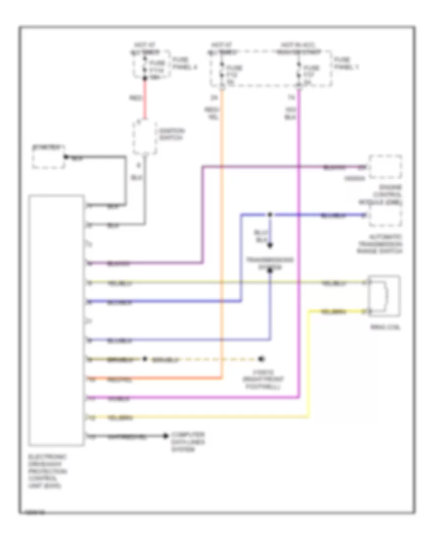
Immobilizer Wiring Diagram for BMW 540i 1998
List of elements for Immobilizer Wiring Diagram for BMW 540i 1998:
- Automatic transmission range switch
- Computer data lines system
- Electronic driveaway protection control unit (ews)
- Engine control module (dme)
- Fuse f114 50a
- Fuse f12 5a
- Fuse f37 5a
- Fuse panel 1
- Fuse panel 4
- Hot at all times
- Hot in acc, run or start
- Ignition switch
- Red
- Ring coil
- Starter
- Transmissions system
- X10012 (right front footwell)
- X60004
 Čeština
 Dansk
Dansk Deutsch
 Ελληνικά
 English
 English
 Suomi
Suomi Français
 Français
 עברית
עברית Hrvatski
 Magyar
 Italiano
 日本語
日本語 한국어
한국어 Nederlands
 Polski
 Português
 Português
 Română
 Русский
 Slovenčina
 Slovenščina
 Svenska
 Türkçe
 中文 (中国)
 Español