ANTI-LOCK BRAKES
Anti-lock Brake Wiring Diagrams for Nissan Pathfinder SE 2001
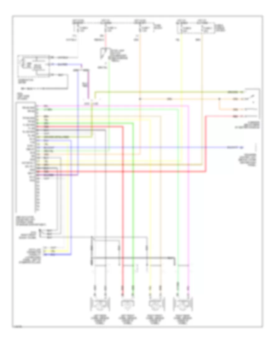
List of elements for Anti-lock Brake Wiring Diagrams for Nissan Pathfinder SE 2001:
- 17u
- 2wd
- 39u
- 4wd
- Abs actuator & electric unit (on right side of engine compartment)
- Abs ind
- Abs st
- Bls
- Combination meter
- Data link connector (consult) (lower dash panel, left of steering column)
- Diag l
- Fl ss
- Fl ss gnd
- Fr ss
- Fr ss gnd
- Fuse & fusible link box
- Fuse 14 10a
- Fuse 7 7.5a
- Fuse 8 10a
- Fuse block
- Fuse c 40a
- Fuse d 40a
- G sensor (below rear of center console)
- G103 (right front shock tower)
- G202 (left side of dash)
- Gnd
- Gswt
- Hot at all times
- Hot in on or start
- Ign
- Left front wheel sensor (inside of wheel)
- Left rear wheel sensor (inside of wheel)
- Motor rly
- Red
- Right front wheel sensor (inside of wheel)
- Right rear wheel sensor (inside of wheel)
- Rl ss
- Rl ss gnd
- Rr ss
- Rr ss gnd
- Rxd
- Sila
- Sol rly
- Solid state
- Stop lamp switch (on bracket, above brake pedal)
- Transfer control unit (behind lower center dash panel)
- Txd
 Čeština
 Dansk
Dansk Deutsch
 Ελληνικά
 English
 English
 Suomi
Suomi Français
 Français
 עברית
עברית Hrvatski
 Magyar
 Italiano
 日本語
日本語 한국어
한국어 Nederlands
 Polski
 Português
 Português
 Română
 Русский
 Slovenčina
 Slovenščina
 Svenska
 Türkçe
 中文 (中国)
 Español