ANTI-THEFT
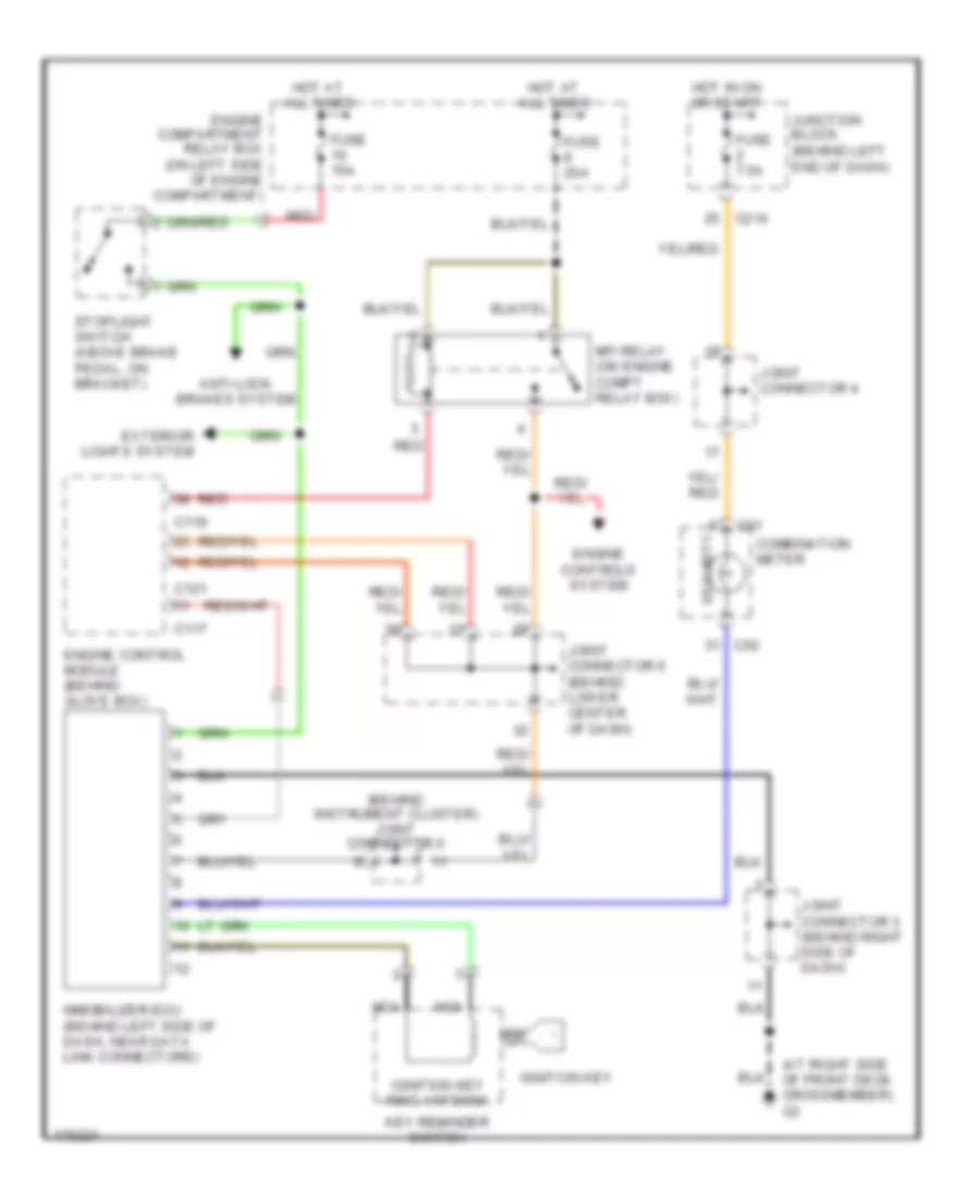
Immobilizer Wiring Diagram, Evolution for Mitsubishi Lancer ES 2003
List of elements for Immobilizer Wiring Diagram, Evolution for Mitsubishi Lancer ES 2003:
- (at right side of front deck crossmember) g3
- (behind instrument cluster) joint connector 5
- All times
- Anti-lock brakes system
- C01
- C02
- C117
- C119
- C121
- C214
- Combination meter
- Engine compartment relay box (on left side of engine compartment)
- Engine control module (behind glove box)
- Engine controls system
- Exterior lights system
- Fuse 15a
- Fuse 20a
- Fuse 7.5a
- Hot at
- Hot in on or start
- Ignition key
- Ignition key ring antenna
- Immobilizer-ecu (behind left side of dash, near data link connectors)
- Joint connector 3 (behind right side of dash)
- Joint connector 4
- Joint connector 6 (behind lower center of dash)
- Junction block (behind left end of dash)
- Key reminder switch
- Mfi relay (on engine compt relay box)
- Nca
- Red
- Security
- Stoplight switch (above brake pedal, on bracket)
 Čeština
 Dansk
Dansk Deutsch
 Ελληνικά
 English
 English
 Suomi
Suomi Français
 Français
 עברית
עברית Hrvatski
 Magyar
 Italiano
 日本語
日本語 한국어
한국어 Nederlands
 Polski
 Português
 Português
 Română
 Русский
 Slovenčina
 Slovenščina
 Svenska
 Türkçe
 中文 (中国)
 Español