ANTI-THEFT
Forced Entry Wiring Diagram for Suzuki Grand Vitara Limited 2011
 https://portal-diagnostov.com/license.html
Automotive Electricians Portal FZCO
Automotive Electricians Portal FZCO
https://portal-diagnostov.com/license.html
https://portal-diagnostov.com/license.html
Automotive Electricians Portal FZCO
Automotive Electricians Portal FZCO
List of elements for Forced Entry Wiring Diagram for Suzuki Grand Vitara Limited 2011:
- (behind left end of dash) junction connector g82
- (on steering column assembly) g17
- Body control module (bcm) (behind left side of dash)
- Can
- Combination meter
- Computer data lines system
- Cpu
- Diode 3 (behind right kick panel)
- Dome fuse 10a
- Door ind
- Door lock fuse 20a
- Driver side power door lock main switch
- Exterior lights system
- G03
- G07
- G08
- G18
- G30
- G31
- G32
- G72
- High
- Horns system
- Hot at all times
- Hot in on or start
- Interior lights system
- J01
- J09
- J16
- J21
- Joint connector g76 (behind left side of dash)
- Junction block (j/b) (behind left side of dash)
- Junction connector l22 (in right "d" pillar)
- Keyless entry receiver (if equipped) (behind lower center of dash)
- L07
- L08
- L09
- L13
- L27
- L31
- L37
- L42
- Left front door switch (on left "b" pillar)
- Left front power door lock actuator
- Left rear door lock motor (in left rear door)
- Left rear door switch (on left "c" pillar)
- Lock
- Low
- Main switch (key switch)
- Meter fuse 10a
- O01
- Off
- Passenger side door lock sub switch
- Pnk
- Rear end door lock motor (at lower left side of rear door)
- Rear end door switch (base of left "d" pillar)
- Red
- Right front door switch (on right "b" pillar)
- Right front power door lock actuator
- Right rear door lock motor (in right rear door)
- Right rear door switch (on right "c" pillar)
- Security option
- Un- lock
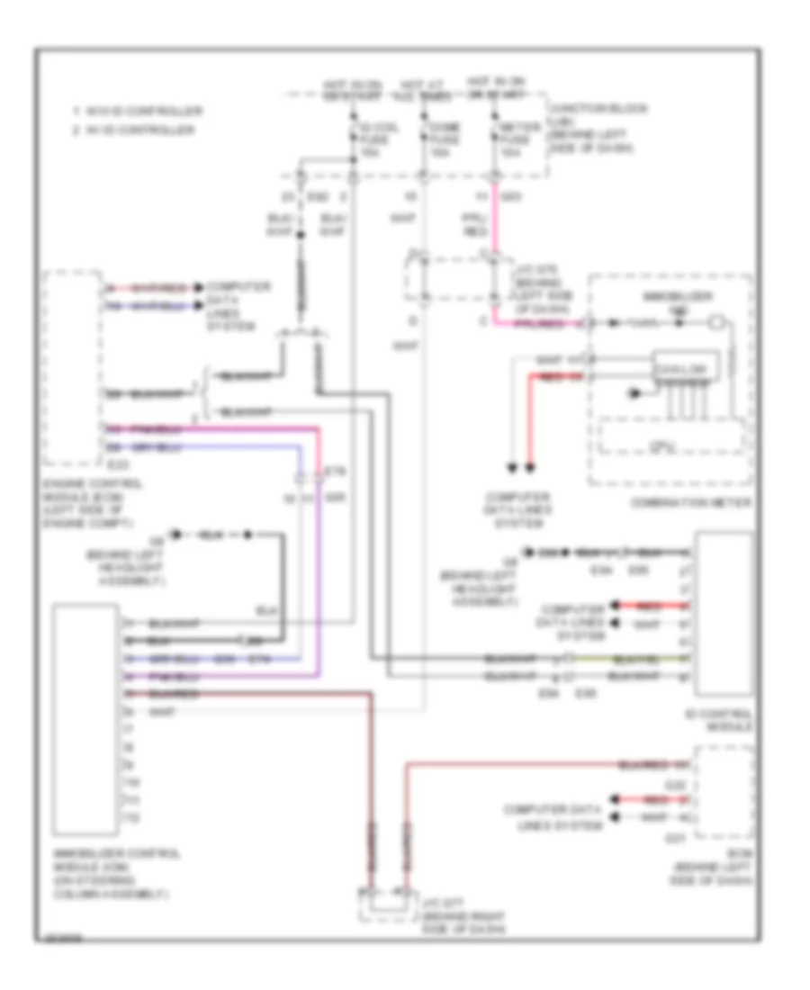
Immobilizer Wiring Diagram for Suzuki Grand Vitara Limited 2011
List of elements for Immobilizer Wiring Diagram for Suzuki Grand Vitara Limited 2011:
- Bcm (behind left side of dash)
- Can low can high
- Combination meter
- Computer data
- Computer data lines system
- Cpu
- Dome fuse 10a
- E23
- E74
- E78
- E82
- E94
- E95
- Engine control module (ecm) (left side of engine compt)
- G03
- G05
- G31
- G32
- G36
- G8 (behind left headlight assembly)
- Hot at all times
- Hot in on or start
- Id control module
- Ig coil fuse 15a
- Immobilizer control module (icm) (on steering column assembly)
- Immobilizer ind
- J/c g76 (behind left side of dash)
- J/c g77 (behind right side of dash)
- Junction block (j/b) (behind left side of dash)
- Lines system
- Meter fuse 10a
- Red
- W/ id controller
- W/o id controller

 Čeština
 Dansk
Dansk Deutsch
 Ελληνικά
 English
 English
 Suomi
Suomi Français
 Français
 עברית
עברית Hrvatski
 Magyar
 Italiano
 日本語
日本語 한국어
한국어 Nederlands
 Polski
 Português
 Português
 Română
 Русский
 Slovenčina
 Slovenščina
 Svenska
 Türkçe
 中文 (中国)