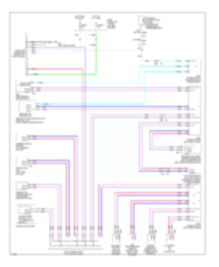
COMPUTER DATA LINES
Computer Data Lines Wiring Diagram for Nissan NV200 Taxi 2014
List of elements for Computer Data Lines Wiring Diagram for Nissan NV200 Taxi 2014:
- (forward of fuse & fusible link box)
- 11a
- 12a
- 17b
- 18b
- 25a
- Abs actuator & electric unit (control unit) (right rear of engine compt)
- Abs/tcs/vdc control unit
- Air bag diagnosis sensor unit (under center console)
- Av control unit (w/ navigation)
- B11
- Bcm (body control module) (left end of dash)
- Can-h
- Can-l
- Combination meter
- Cpu
- Data link connector
- Data link connector (under left end of dash)
- Dia k
- E16
- E46
- Ecm (left rear of engine compt)
- Eps control unit (left side of dash)
- Fuse 10 10a
- Fuse 3 10a
- Fuse block (j/b) (lower left end of dash)
- Hot at all times
- Hot in on or start
- Ipdm e/r (intelligent power distribution module engine room) (left rear of engine compt)
- Joint connector e01 (center rear of engine compt)
- Joint connector e02 (left end of dash)
- Joint connector m01 (left side of dash)
- Joint connector m02 (left side of dash)
- K-line
- Low tire pressure warning control unit (right side of dash)
- M12
- M18
- M35
- M53
- M61 (left end of dash)
- M69
- M70
- Occupant classification system control unit (under front passenger seat)
- Pnk
- Steering angle sensor (on steering column)
- Tcm (transmission control module)
- Telematics control module (if equipped) (center of dash)
- Unified meter control unit (w/ information display)
 Čeština
 Dansk
Dansk Deutsch
 Ελληνικά
 English
 English
 Suomi
Suomi Français
 Français
 עברית
עברית Hrvatski
 Magyar
 Italiano
 日本語
日本語 한국어
한국어 Nederlands
 Polski
 Português
 Português
 Română
 Русский
 Slovenčina
 Slovenščina
 Svenska
 Türkçe
 中文 (中国)
 Español