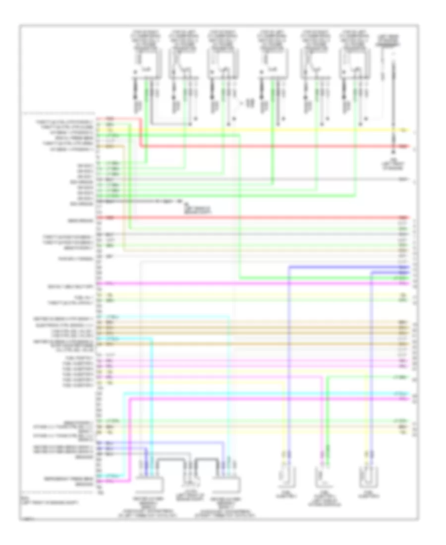
ENGINE PERFORMANCE
2.5L
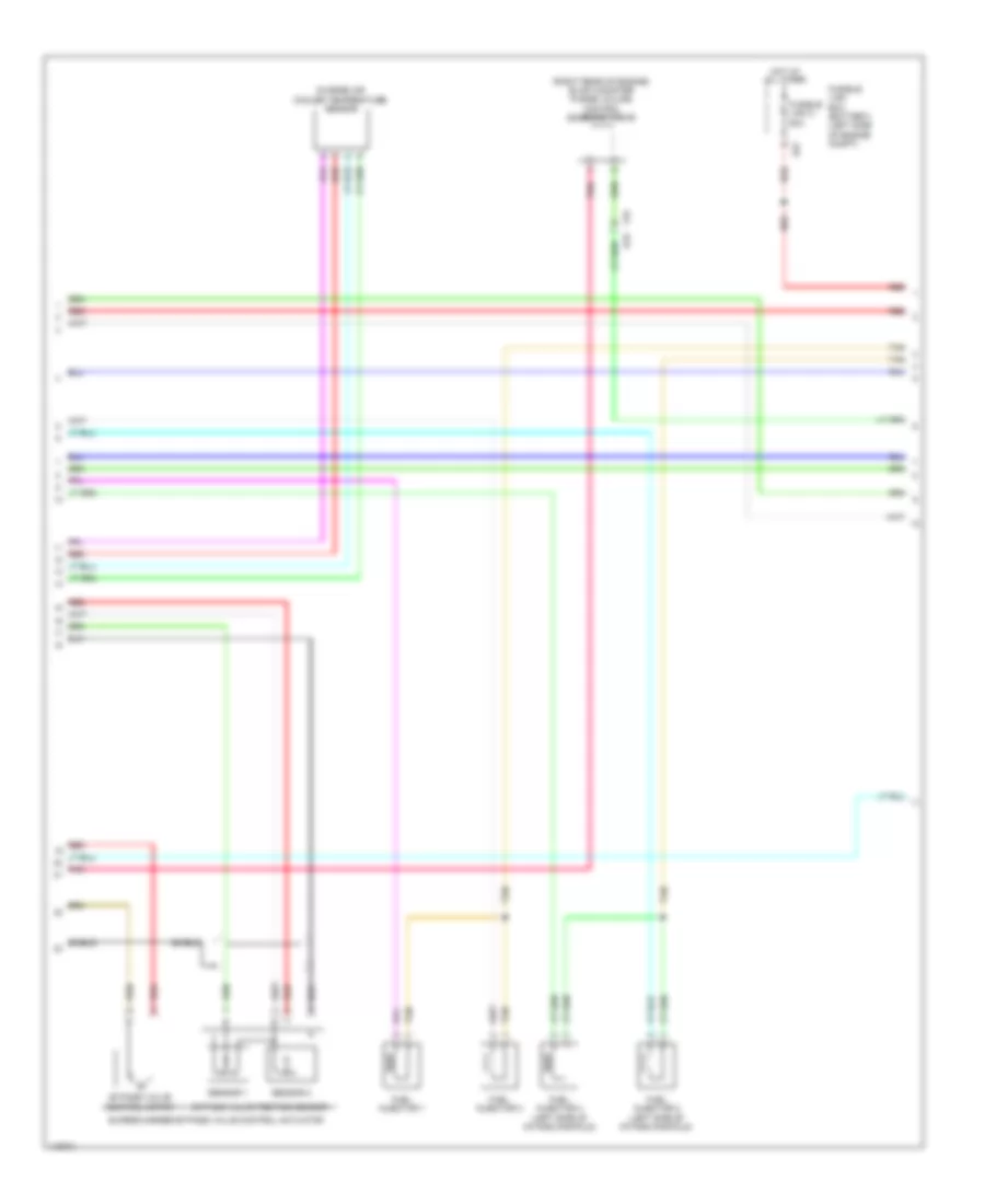
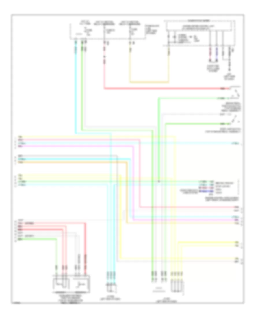
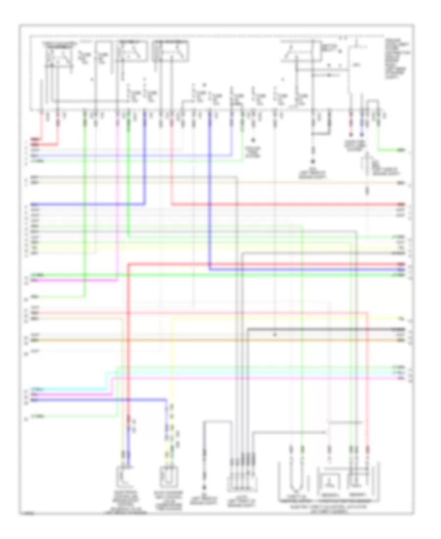
2.5L, Engine Controls Wiring Diagram (1 of 6) for Nissan Pathfinder S 2014
 https://portal-diagnostov.com/license.html
Automotive Electricians Portal FZCO
Automotive Electricians Portal FZCO
https://portal-diagnostov.com/license.html
https://portal-diagnostov.com/license.html
Automotive Electricians Portal FZCO
Automotive Electricians Portal FZCO
List of elements for 2.5L, Engine Controls Wiring Diagram (1 of 6) for Nissan Pathfinder S 2014:
- (left rear of engine compt) e9
- Canister ctrl solenoid valve
- Crankshaft position sensor (pos) (lower left rear of engine)
- E119
- E19 f33
- E58
- Ecm (left front of engine compt)
- Ecm rly (self shut-off)
- Eng oil press sens
- Engine oil pressure sensor (lower front of engine)
- F51
- Fuel inj 1
- Fuel inj 2
- Fuel inj 3
- Fuel inj 4
- Fuel pmp rly
- Fuel rail pressure sensor
- Fuel rly press sens
- Gnd
- Intake air air temp sens
- Intake air temperature sensor
- Intake manifold runner control valve
- Ipdm e/r (intelligent power distribution e218 module engine room) (left rear of engine compt)
- Knock sens
- Knock sensor
- Mass air flow sens
- Mass airflow sensor (on air cleaner box)
- Pnk
- Position sens
- Press sens
- Red
- Refrigerant pressure sensor (front left side of radiator)
- Sens gnd
- Sens pwr sply
- Sens sply
- Shield
- Supercharger bypass valve control motor relay (in fuse, fusible link & relay box 1)
- Temp sens
- Thr pos sens 1
- Thr pos sens 2
- Throttle ctrl mtr (close)
- Throttle ctrl mtr (open)
- Throttle ctrl mtr pwr sply
- Throttle ctrl mtr rly
- Valve (close)
- Valve (open)
- Valve ctrl mtr
- Valve ctrl mtr pwr sply
- Valve ctrl mtr rly
- Valve position sens 1
- Valve position sens 2
- Valve pwr sply
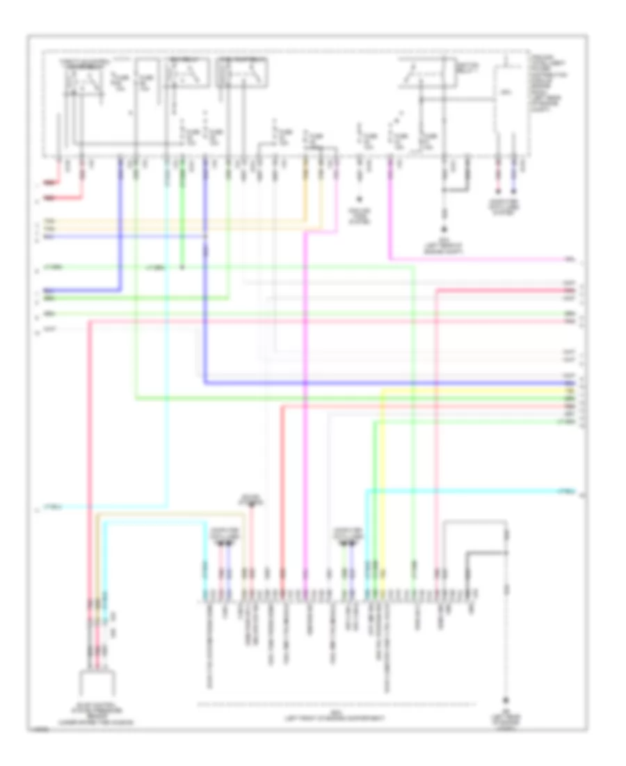
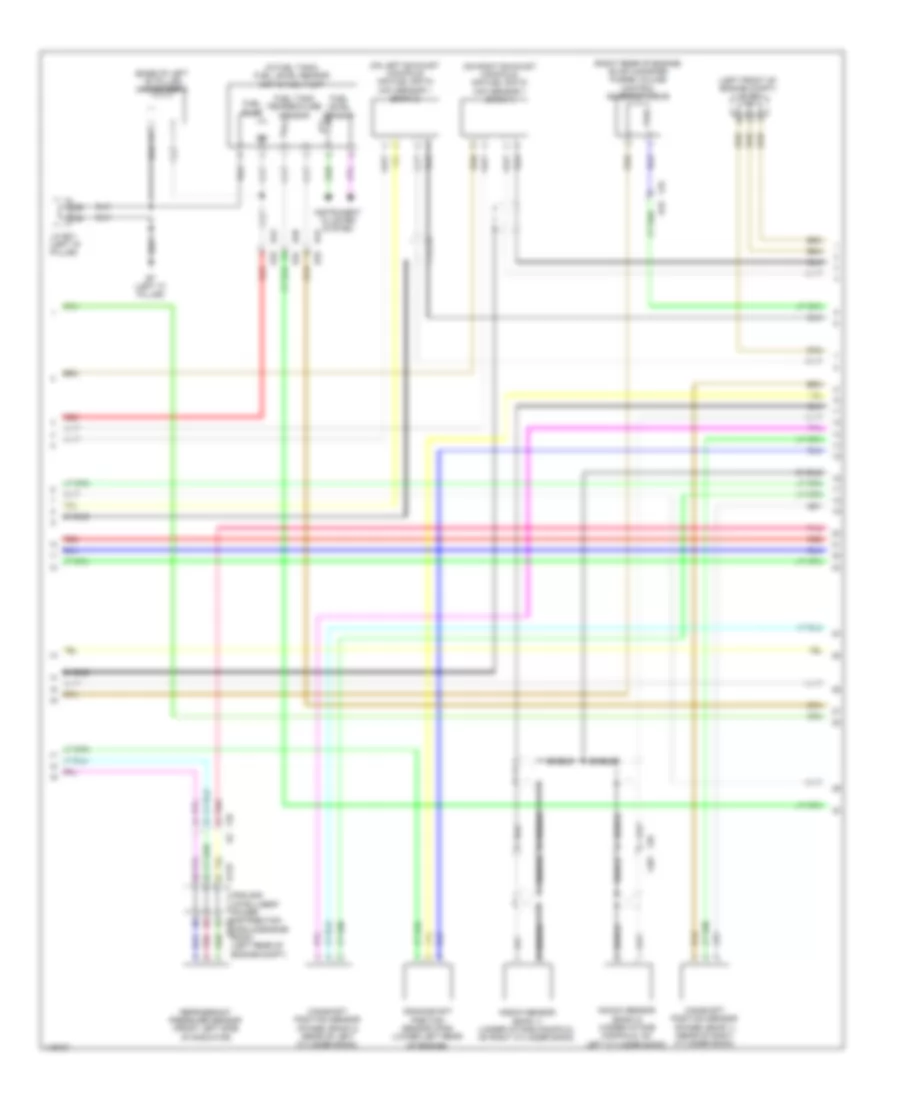
2.5L, Engine Controls Wiring Diagram (2 of 6) for Nissan Pathfinder S 2014
List of elements for 2.5L, Engine Controls Wiring Diagram (2 of 6) for Nissan Pathfinder S 2014:
- (right rear of engine) evap canister purge volume control solenoid valve
- Bypass valve control motor
- Bypass valve position sensor
- Charge air cooler temperature sensor
- E27
- F33 e19
- Fuel injector 1
- Fuel injector 2 (left side of intake manifold)
- Fuel injector 3
- Fuel injector 4 (left side of intake manifold)
- Fusible link box (battery) (left side of engine compt)
- Fusible link c 80a
- Hot at all times
- Pnk
- Red
- Sensor 1
- Sensor 2
- Shield
- Supercharger bypass valve control actuator
- Tan
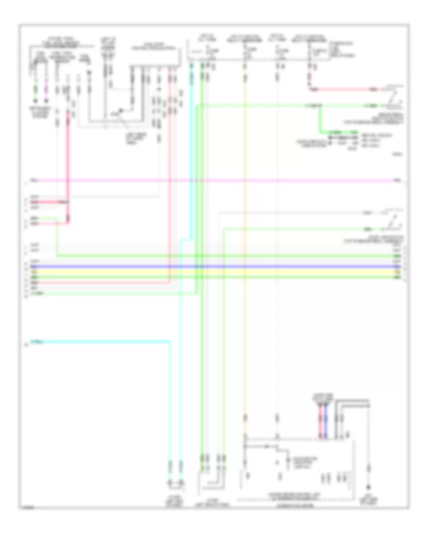
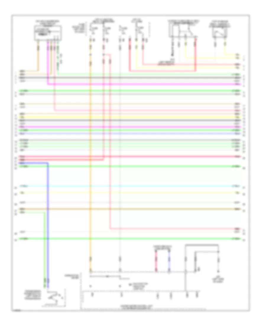
2.5L, Engine Controls Wiring Diagram (3 of 6) for Nissan Pathfinder S 2014
List of elements for 2.5L, Engine Controls Wiring Diagram (3 of 6) for Nissan Pathfinder S 2014:
- B40
- Brk pdl position sw
- Can-h
- Can-l
- Computer data lines system
- Cooling fans system
- Cpu
- E118
- E119
- E121
- E15 (left rear of engine compt)
- E16
- E34
- E9 (left rear of engine compt)
- Ecm (left front of engine compartment)
- Ecm relay
- Eng spd o/p sig
- Evap canister vent ctrl valve
- Evap control system pressure sensor (under spare tire housing)
- Evap ctrl system press sens
- F19
- F24
- Fuel pmp ctrl module
- Fuel pump relay
- Fuel tank press sens
- Fuse 10a
- Fuse 15a
- Gnd
- Hev can-h
- Hev can-l
- Ignition relay 1
- Ignition sw
- Ipdm e/r (intelligent power distribution module engine room) (left rear of engine compt)
- Pnk
- Pwr sply
- Red
- Sens gnd
- Sens pwr sply
- Sound systems
- Stp lmp sw
- Tan
- Throttle control motor relay
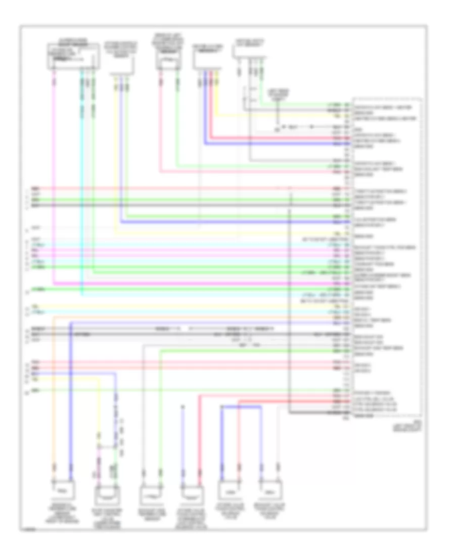
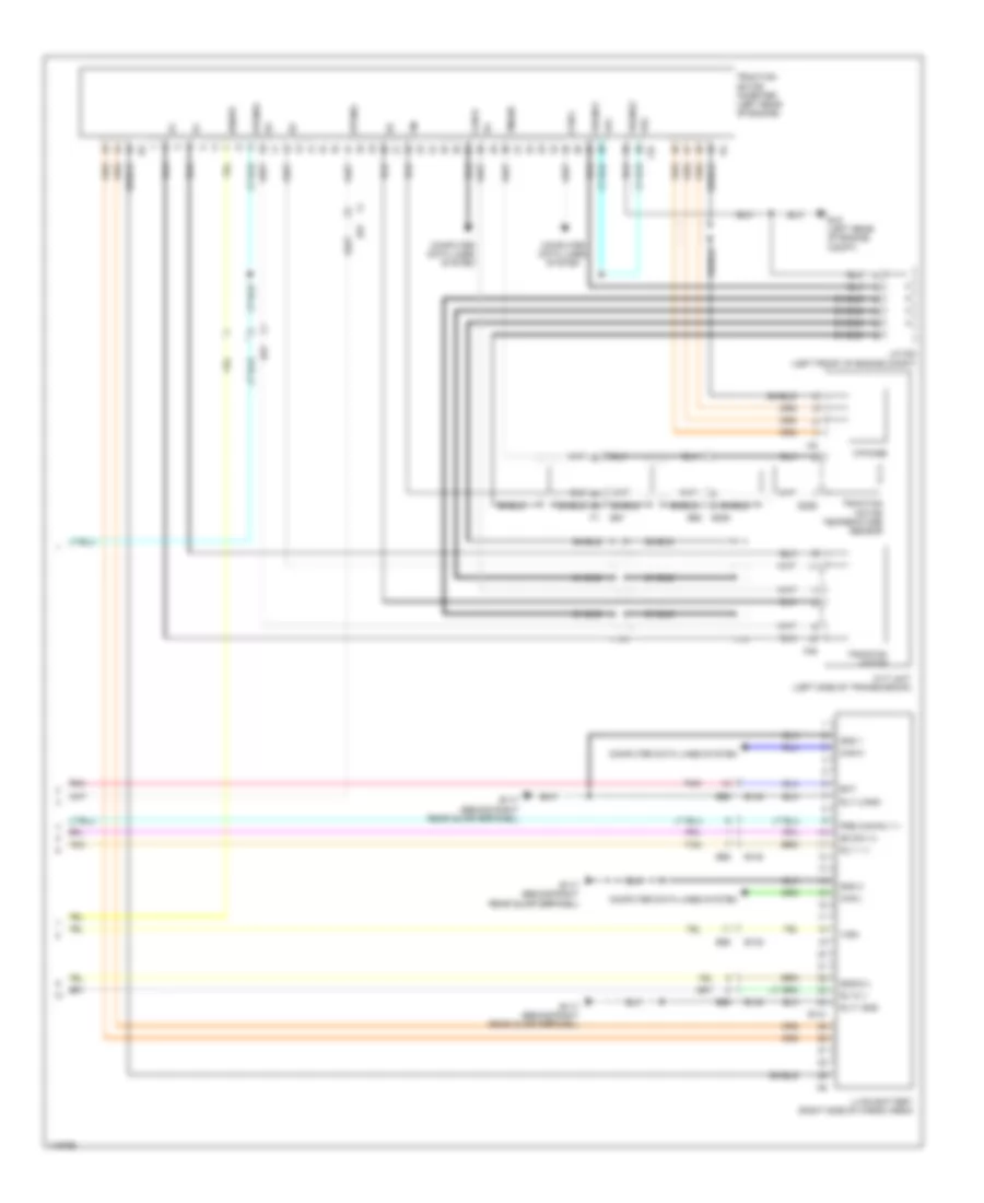
2.5L, Engine Controls Wiring Diagram (4 of 6) for Nissan Pathfinder S 2014
List of elements for 2.5L, Engine Controls Wiring Diagram (4 of 6) for Nissan Pathfinder S 2014:
- (in fuel tank) fuel level sensor unit & fuel pump
- (left "d" pillar) j/c b16
- (left rear of cargo area)
- 13p
- B19
- B40 e34
- B43 e33
- Bat
- Brake pedal position switch (top of brake pedal assembly)
- Brk pdl pos sw
- Can-h
- Can-l
- Combination meter
- Computer data lines system
- E130
- E28
- Fuel level sensor
- Fuel pump
- Fuel pump control module (fpcm)
- Fuel tank temperature sensor
- Fuse 10a
- Fuse 30 10a
- Fuse 5a
- Fuse block (j/b) (left end of dash)
- Gnd 1
- Gnd 2
- Hev can-h
- Hev can-l
- Hot at all times
- Hot w/ ignition relay 2 energized
- Hpcm
- Ign
- Instrument cluster system
- J/c e01 (left end of dash)
- J/c e22 (left end of dash)
- M24
- M57 (left side of dash)
- Malfunction indicator lamp (mil)
- Pnk
- Red
- Shield
- Stop lamp switch (top of brake pedal assembly)
- Tan
- Unified meter control unit (w/ information display)
2.5L, Engine Controls Wiring Diagram (5 of 6) for Nissan Pathfinder S 2014
List of elements for 2.5L, Engine Controls Wiring Diagram (5 of 6) for Nissan Pathfinder S 2014:
- (left rear of engine compt) e15
- (left rear of engine) condenser-1
- (on throttle body) electric throttle control actuator
- (or red)
- (top of left cylinder head) ignition coil 2 (w/ power transistor)
- (top of left cylinder head) ignition coil 4 (w/ power transistor)
- (top of right cylinder head) ignition coil 1 (w/ power transistor)
- (top of right cylinder head) ignition coil 3 (w/ power transistor)
- Camshaft position sensor
- E87
- Eng mount drive sig
- Eng mount ground
- Eng mount pwr sply 1
- Eng mount pwr sply 2
- Eng mount sig
- Engine mount control module
- Exhaust valve timing control position sensor
- F40
- F60 (left front of engine)
- Front electronic controlled engine mount
- Fuse & fusible link box (left side of engine compt)
- Fuse 5a
- Ground
- Hot at all times
- J/c e06 (left side of dash)
- Nca
- Plug spark
- Pnk
- Rear electronic controlled engine mount
- Red
- Sensor 1
- Sensor 2
- Shield
- Spark plug
- Throttle control motor
- Throttle position sensor
- Wire loop
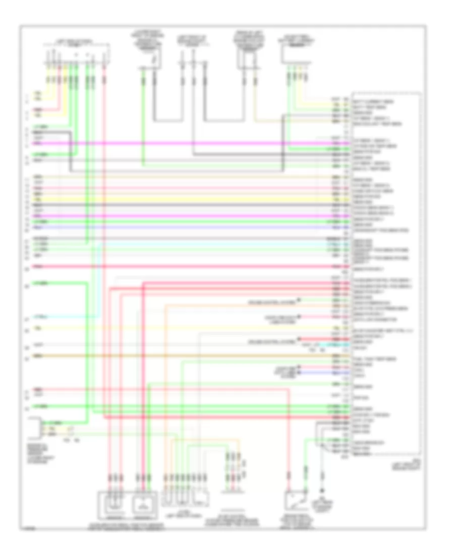
2.5L, Engine Controls Wiring Diagram (6 of 6) for Nissan Pathfinder S 2014
List of elements for 2.5L, Engine Controls Wiring Diagram (6 of 6) for Nissan Pathfinder S 2014:
- (80 to 85 not used pins)
- (96 to 100 not used pins)
- (left rear of engine compt)
- (or red)
- (rear of left cylinder bank) engine coolant temperature sensor
- Air fuel ratio (a/f) sensor 1
- Air ratio (a/f) sens 1
- Air ratio (a/f) sens 1 heater
- Camshaft pos sens
- Ctrl solenoid valve
- E34 b40
- E87
- Ecm (left front of engine compt)
- Eng coolant temp sens
- Eng mount sig
- Eng oil temp sens
- Engine oil temperature sensor (lower right front of engine)
- Evap canister vent control valve (under spare tire housing)
- Exhaust gas temp sens
- Exhaust gas temperature sensor
- Exhaust timing ctrl pos sens
- Exhaust valve timing control solenoid valve
- F2 e58
- F40
- F52
- Gnd
- Heated oxygen sens 2
- Heated oxygen sens 2 heater
- Heated oxygen sensor 2
- Ign sig 1
- Ign sig 2
- Ign sig 3
- Ign sig 4
- Intake air temp sens 2
- Intake air temperature sensor 2
- Intake manifold runner control valve position sensor
- Intake valve timing control intermediate lock control solenoid valve
- Intake valve timing control solenoid valve
- Lck ctrl sol valve
- Pnk
- Pwr sply for ecm
- Red
- Sens gnd
- Sens pwr sply
- Shield
- Super charger boost sens
- Supercharge boost sensor
- Throttle position sens 1
- Throttle position sens 2
- Valve position sens
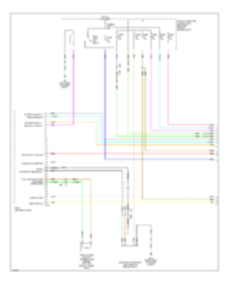
2.5L, Hybrid System Wiring Diagram (1 of 5) for Nissan Pathfinder S 2014
List of elements for 2.5L, Hybrid System Wiring Diagram (1 of 5) for Nissan Pathfinder S 2014:
- B148
- E131
- E207
- E214 (right front of engine compt)
- E57
- E68
- E9 (left rear of engine compt)
- Electric water pmp
- Electric water pump (left front of engine compt)
- Fuse 10a
- Fusible link v 50a
- Hi vol cooling water
- High voltage coolant temperature sensor (top left near cylinder bank)
- High voltage fuse, fusible link & relay box (rear of engine compt)
- Hot at all times
- Hpcm (center of dash)
- Inter lck sw
- Nca
- Pnk
- Pre-charge sig
- Red
- Self shut off relay
- Self shut off rly
- Sensor gnd
- Service plug
- Shield
- Str mtr rly ctrl sig
- System main rly 1
- System main rly 2
- Tan
- Temp sens
- Water pmp (feed back)
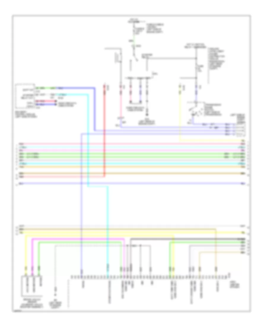
2.5L, Hybrid System Wiring Diagram (2 of 5) for Nissan Pathfinder S 2014
List of elements for 2.5L, Hybrid System Wiring Diagram (2 of 5) for Nissan Pathfinder S 2014:
- (left side of engine compt) j/c e21
- 44g
- 78g
- Avcc-mvpres
- Batt current sens
- Batt temp sens
- Bcm (body control module) (left side of dash)
- Brake vacuum sensor (on brake vacuum booster assembly)
- Brk vacuum sw
- Can-h
- Can-l
- Computer data lines system
- Cpu
- E119
- E120
- E132
- E15 (left rear of engine compt)
- E152
- E57
- E57 f1
- E9 (left rear of engine compt)
- F24
- Fuse & fusible link box (left side of engine compt)
- Fuse 10a
- Fusible link k 40a
- Gnd
- Gnda-mvpres
- Hot at all times
- Hot w/ ignition relay 1 energized
- Hpcm (center of dash)
- Ipdm e/r (intelligent power distribution module engine room) (left rear of engine compt)
- M18
- M19
- M31
- Mvpres
- P/n sig
- Pnk
- Pwr sply
- Red
- Sens gnd
- Sens pwr sply
- Shield
- Shift n/p
- Starter relay
- Starter relay out
- Str mtr status sig
- Tan
- Transmission range switch (left side of transmission)
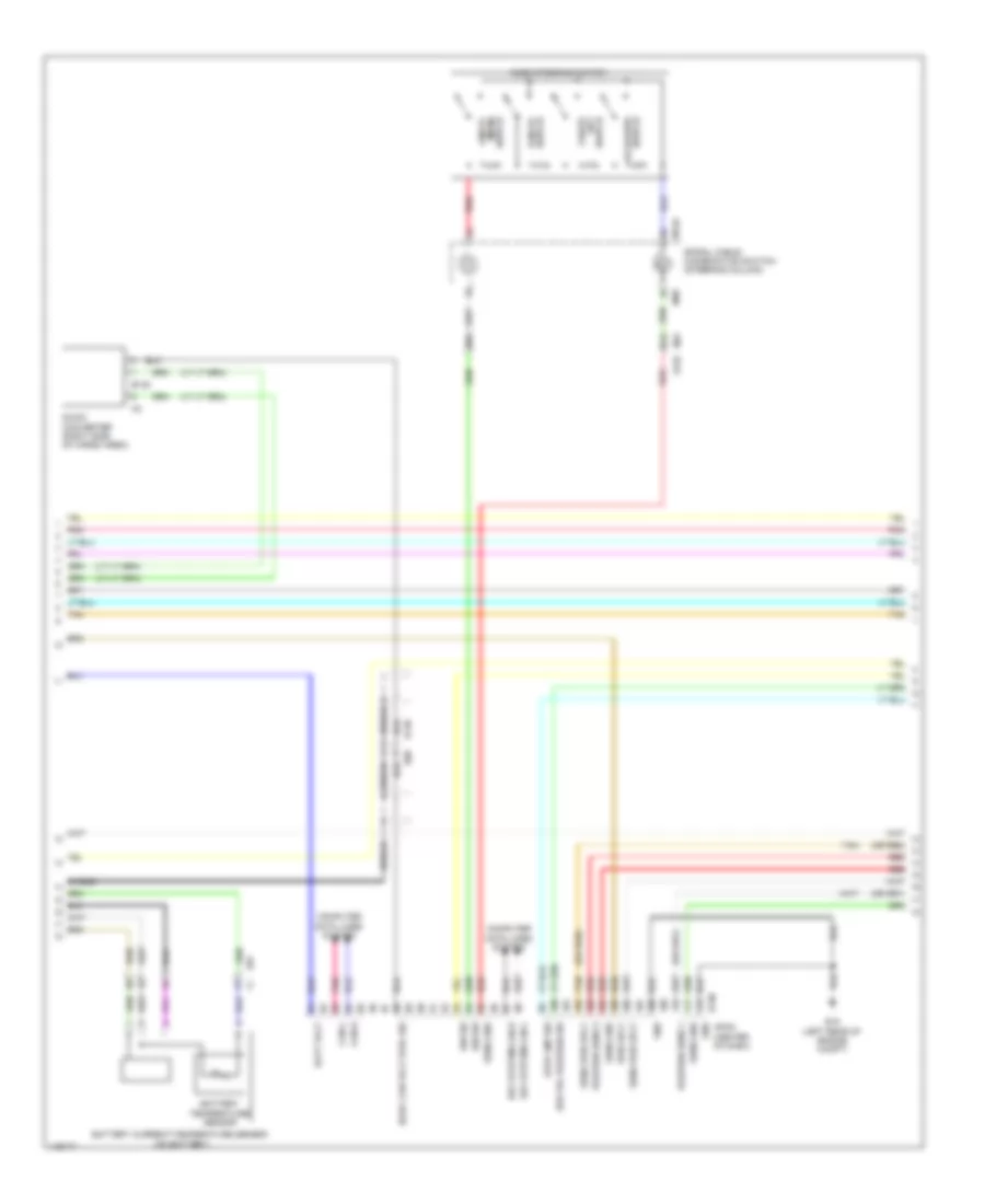
2.5L, Hybrid System Wiring Diagram (3 of 5) for Nissan Pathfinder S 2014
List of elements for 2.5L, Hybrid System Wiring Diagram (3 of 5) for Nissan Pathfinder S 2014:
- (or red)
- 80g
- 81g
- Ascd steering switch
- B135
- B148
- Batt volt
- Battery current/temperature sensor (on battery)
- Battery temperature sensor
- Brk pdl position sw
- Can-h
- Can-l
- Cancel switch
- Coast/ set switch
- Computer data lines system
- Dc/dc con volt stbl sig
- Dc/dc converter (right side of cargo area)
- E130
- E15 (left rear of engine compt)
- E57
- E68
- Gnd
- Hev system can-h
- Hev system can-l
- Hpcm (center of dash)
- Ign sig
- Ign sw
- M149
- M30
- M31 e152
- Pnk
- Position sens 1
- Position sens 2
- Pwr sply
- Red
- Sens gnd
- Sens pwr sply
- Shield
- Spiral cable (combination switch) (steering column)
- Stop lmp sw
- Switch (main) on/off
- Switch accel/res
- Tan
2.5L, Hybrid System Wiring Diagram (4 of 5) for Nissan Pathfinder S 2014
List of elements for 2.5L, Hybrid System Wiring Diagram (4 of 5) for Nissan Pathfinder S 2014:
- (or red)
- (w/ information display)
- Accelerator pedal position sensor (top of accelerator pedal assembly)
- Brake pedal position switch (top of brake pedal assembly)
- Brk pdl pos sw
- Can-h
- Can-l
- Combination meter
- Computer data lines system
- E16
- E28
- Engine control module (ecm) (left front of engine compt)
- Ev ind lamp
- Fuse 10a
- Fuse 30 10a
- Fuse 5a
- Fuse block (j/b) (left end of dash)
- Hot at all times
- Hot w/ ignition relay 2 energized
- Hybrid system warning lamp
- J/c e01 (left end of dash)
- J/c e22 (left end of dash)
- M24
- M57 (left side of dash)
- Pnk
- Red
- Sensor 1
- Sensor 2
- Stop lamp switch (top of brake pedal assembly)
- Stop lmp sw
- Tan
- Unified meter control unit
2.5L, Hybrid System Wiring Diagram (5 of 5) for Nissan Pathfinder S 2014
List of elements for 2.5L, Hybrid System Wiring Diagram (5 of 5) for Nissan Pathfinder S 2014:
- 3-phase
- B117 (behind right rear quarterpanel)
- B131
- B148
- Bat
- Can-h
- Can-l
- Computer data lines system
- Cvt unit (left side of transmission)
- E15 (left rear of engine compt)
- E350
- E356
- E57
- E60
- E68
- F37
- F46
- Gnd 1
- Gnd 2
- Ignsw
- J/c f02 (left front of engine compt)
- Li-ion battery (right side of cargo area)
- Opsns+
- Opsns-
- Pnk
- Pre chg rly v
- Rly 1 v
- Rly 2 gnd
- Rly1 gnd
- Rly2 v
- Sd sw (+)
- Sdsw(-)
- Shield
- Tan
- Tmgnd
- Traction motor
- Traction motor inverter (left rear of engine)
- Traction motor temperature sensor
- Vb1
- Vb2
- Vbgnd1
- Vbgnd2
- Vign
3.5L
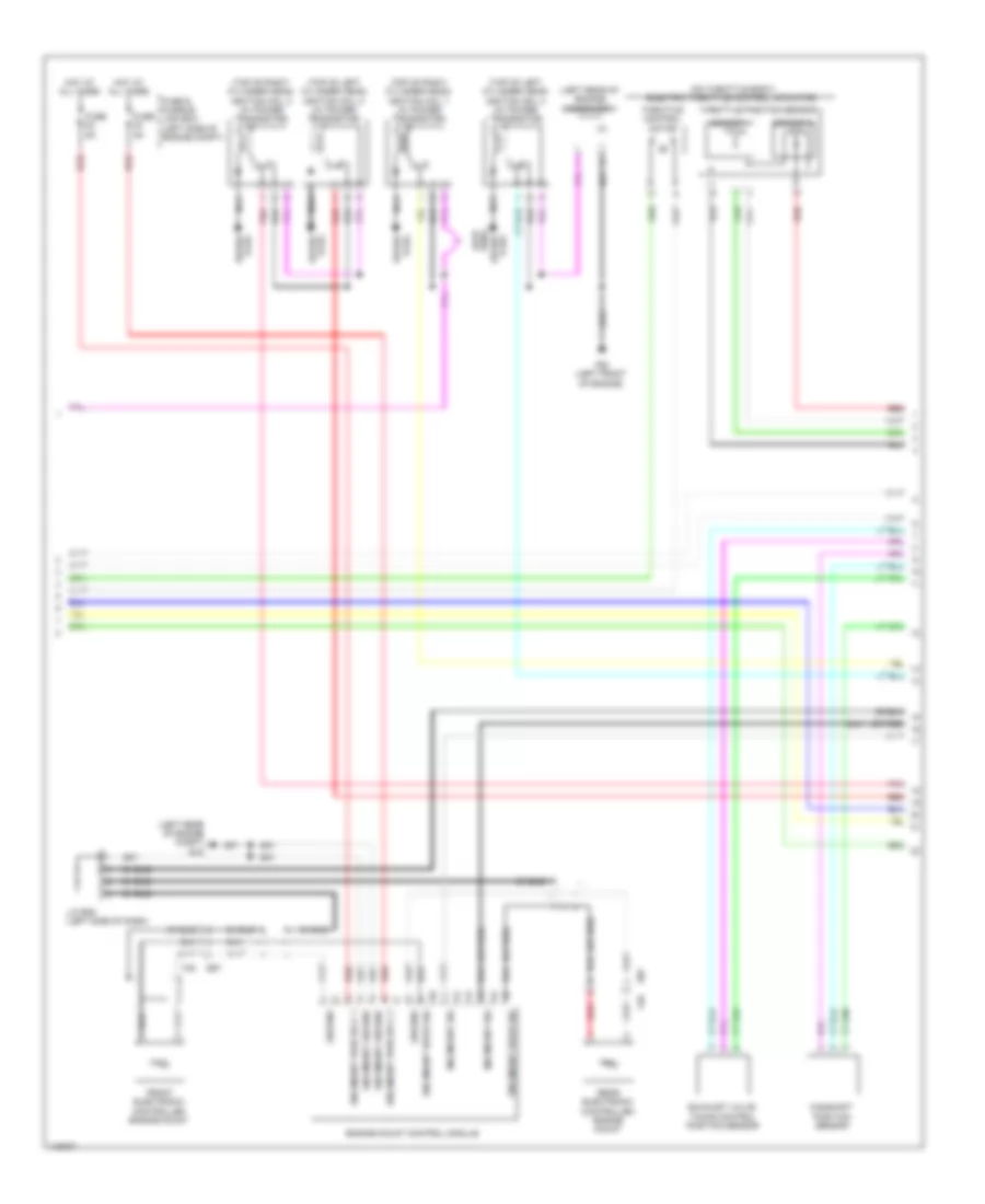
3.5L, Engine Performance Wiring Diagram (1 of 6) for Nissan Pathfinder S 2014
List of elements for 3.5L, Engine Performance Wiring Diagram (1 of 6) for Nissan Pathfinder S 2014:
- (left rear of engine) condenser 1
- (top of left cylinder bank) ignition coil 2 (w/ power transistor)
- (top of left cylinder bank) ignition coil 4 (w/ power transistor)
- (top of left cylinder bank) ignition coil 6 (w/ power transistor)
- (top of right cylinder bank) ignition coil 1 (w/ power transistor)
- (top of right cylinder bank) ignition coil 3 (w/ power transistor)
- (top of right cylinder bank) ignition coil 5 (w/ power transistor)
- A/f sens 1 htr (bank 1)
- A/f sens 1 htr (bank 2)
- E9 (left rear of engine compt)
- Ecm (left front of engine compt)
- Ecm ground
- Ecm rly (self shut-off)
- Electronic ctrl eng sol vlv
- Eng oil press sens
- F51
- F52
- F59 (left front of engine)
- Fuel inj 1
- Fuel injector 2
- Fuel injector 3
- Fuel injector 4
- Fuel injector 4 (left side of intake manifold)
- Fuel injector 5
- Fuel injector 6
- Fuel pump rly
- Heated o2 sens 2 htr 1(bank 1)
- Heated o2 sens 2 htr 2(bank 2) evap canister purge vol ctrl sol valve
- Heated oxygen sens 2 (bank 1)
- Heated oxygen sens 2 (bank 2)
- Heated oxygen sensor 2 (bank 1) (in exhaust, downstream of right three way catalyst)
- Heated oxygen sensor 2 (bank 2) (in exhaust, downstream of left three way catalyst)
- Ign sig 1
- Ign sig 2
- Ign sig 3
- Ign sig 4
- Ign sig 5
- Ign sig 6
- Intake vlv timing ctrl sol vlv (bank 2)
- J/c f04 (left front of engine compt)
- Nca
- Plug spark
- Pwr sply for ecm
- Red
- Refrigerant press sens
- Sens gnd
- Sens ground
- Sens pwr sply
- Sens pwr sply intake vlv timing ctrl sol vlv (bank 1)
- Spark plug
- Throttle ctrl mtr (close)
- Throttle ctrl mtr (open)
- Throttle ctrl mtr pwr sply
- Throttle ctrl mtr rly
- Throttle position sens 1
- Throttle position sens 2
- Vias ctrl sol valve 1
- Vias ctrl sol valve 2
- Wire loop
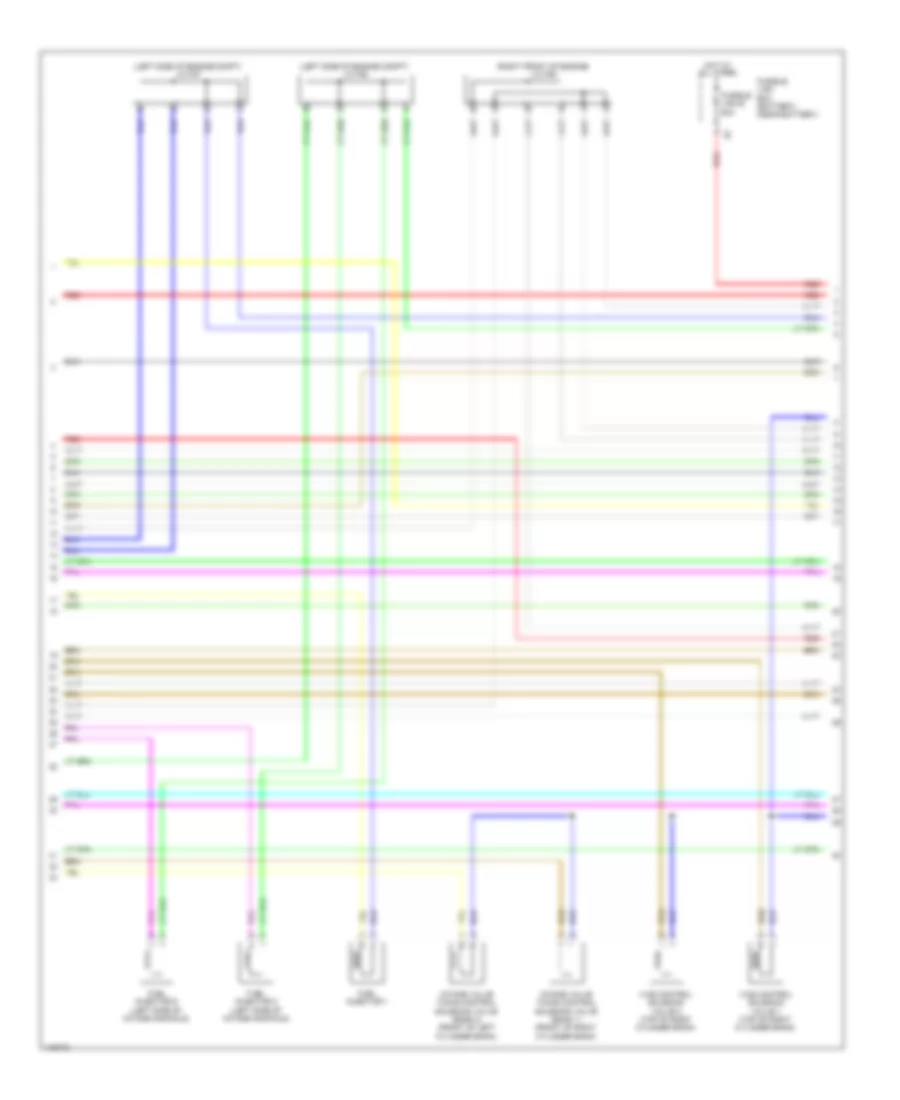
3.5L, Engine Performance Wiring Diagram (2 of 6) for Nissan Pathfinder S 2014
List of elements for 3.5L, Engine Performance Wiring Diagram (2 of 6) for Nissan Pathfinder S 2014:
- (left side of engine compt) j/c f07
- (left side of engine compt) j/c f08
- (right front of engine) j/c f09
- Fuel injector 1
- Fuel injector 2 (left side of intake manifold)
- Fuel injector 6 (left side of intake manifold)
- Fusible link box (battery) (near battery)
- Fusible link e 80a
- Hot at all times
- Intake valve timing control solenoid valve (bank 1) (front of right cylinder bank)
- Intake valve timing control solenoid valve (bank 2) (front of left cylinder bank)
- Red
- Vias control solenoid valve 1 (top of right cylinder bank)
- Vias control solenoid valve 2 (top of right cylinder bank)
3.5L, Engine Performance Wiring Diagram (3 of 6) for Nissan Pathfinder S 2014
List of elements for 3.5L, Engine Performance Wiring Diagram (3 of 6) for Nissan Pathfinder S 2014:
- Computer data lines system
- Cooling fans system
- Cpu
- E118
- E119
- E121
- E15 (left rear of engine compt)
- E2 f32
- E34 b40
- E9 (left rear of engine compt)
- Ecm relay
- Electric throttle control actuator (on throttle body)
- Electronic controlled engine mount control solenoid valve (left front of engine)
- Evap canister vent control valve (under spare tire housing)
- F19
- F24
- F32 e2
- Fuel pump relay
- Fuse 10a
- Fuse 15a
- Ignition relay 1
- Ipdm e/r (intelligent power distribution module engine room) (left rear of engine compt)
- J/c e05 (left side of engine compt)
- J/c f01 (left front of engine compt)
- Pnk
- Red
- Sensor 1
- Sensor 2
- Shield
- Throttle control motor
- Throttle control motor relay
- Throttle position sensor
3.5L, Engine Performance Wiring Diagram (4 of 6) for Nissan Pathfinder S 2014
List of elements for 3.5L, Engine Performance Wiring Diagram (4 of 6) for Nissan Pathfinder S 2014:
- (base of left " b" pillar) condenser 2
- (in fuel tank) fuel level sensor unit & fuel pump
- (left front of engine compt) j/c f04
- (on left exhaust manifold) air fuel ratio (a/f) sensor 1 (bank 2)
- (on right exhaust manifold) air fuel ratio (a/f) sensor 1 (bank 1)
- (right rear of engine) evap canister purge volume control solenoid valve
- B40 e34
- B43 e33
- B7 (left "c" pillar)
- Camshaft position sensor (phase) (bank 1) (rear of right cylinder bank)
- Camshaft position sensor (phase) (bank 2) (rear of left cylinder bank)
- Crankshaft position sensor (pos) (lower left rear of engine)
- E119
- F26 f201
- F32 e2
- F33 e19
- Fuel level sensor
- Fuel pump
- Fuel tank temperature sensor
- Instrument cluster system
- Ipdm e/r (intelligent power distribution e218 module engine room) (left rear of engine compt)
- J/c b01 (left "d" pillar)
- Knock sensor (bank 1) (under intake manifold, on right cylinder bank)
- Knock sensor (bank 2) (under intake manifold, on left cylinder bank)
- Pnk
- Red
- Refrigerant pressure sensor (front left side of radiator)
- Shield
3.5L, Engine Performance Wiring Diagram (5 of 6) for Nissan Pathfinder S 2014
List of elements for 3.5L, Engine Performance Wiring Diagram (5 of 6) for Nissan Pathfinder S 2014:
- (in right fuse & relay box) stop lamp relay
- (on air cleaner box) mass airflow sensor
- (top of brake pedal assembly) stop lamp switch
- 13p
- Bat
- Can-h
- Can-l
- Combination meter
- Computer data lines system
- E15 (left rear of engine compt)
- E28
- F33 e19
- Fuse 10a
- Fuse 5a
- Fuse block (j/b) (left end of dash)
- Gnd1
- Gnd2
- Hot at all times
- Hot w/ ignition relay 2 energized
- Ign
- Intake air temperature sensor
- M24
- M57 (left side of dash)
- Malfunction indicator lamp (mil)
- Pnk
- Red
- Shield
- Tan
- Transmission range switch (left side of transmission)
- Unified meter control unit (w/ information display)
3.5L, Engine Performance Wiring Diagram (6 of 6) for Nissan Pathfinder S 2014
List of elements for 3.5L, Engine Performance Wiring Diagram (6 of 6) for Nissan Pathfinder S 2014:
- (left end of dash) j/c e01
- (left front of engine compt) j/c f04
- (lower right front of engine) engine oil temperature sensor
- (on battery) battery current sensor
- (rear of left cylinder bank) engine coolant temperature sensor
- A/f sens 1 (bank 1)
- A/f sens 1 (bank 2)
- Accelerator pdl pos sens 1
- Accelerator pdl pos sens 2
- Accelerator pedal position sensor (top of accelerator pedal assembly)
- Ascd brake sw
- Ascd steering sw
- Batt current sens
- Batt temp sens
- Brake pedal position switch (top of brake pedal assembly)
- Can-h
- Can-l
- Computer data lines system
- Crankshaft pos sens (pos)
- Cruise control system
- Data link connector
- E16
- E34 b40
- E9 (left rear of engine compt)
- Ecm (left front of engine compt)
- Ecm gnd
- Eng coolant temp sens
- Eng oil temp sens
- Engine oil pressure sensor (lower front of engine)
- Evap canister vent ctrl vlv
- Evap control system pressure sensor (under spare tire housing)
- Evap ctrl sys press sens
- F32
- F52
- Fuel tank temp sens
- Ign sw
- Intake air temp sens
- J/c e01 (left end of dash)
- Knock sens (bank 1)
- Knock sens (bank 2)
- Mass air flow sens
- Pnk
- Pnp sig
- Pwr sply for ecm
- Red
- Sens gnd
- Sens gnd camshaft pos sens (phase) (bank 2) camshaft pos sens (phase) (bank 1)
- Sens pwr sig
- Sens pwr sply
- Sensor 1
- Sensor 2
- Shield
- Stp lp sw
- Tan

 Čeština
 Dansk
Dansk Deutsch
 Ελληνικά
 English
 English
 Suomi
Suomi Français
 Français
 עברית
עברית Hrvatski
 Magyar
 Italiano
 日本語
日本語 한국어
한국어 Nederlands
 Polski
 Português
 Português
 Română
 Русский
 Slovenčina
 Slovenščina
 Svenska
 Türkçe
 中文 (中国)