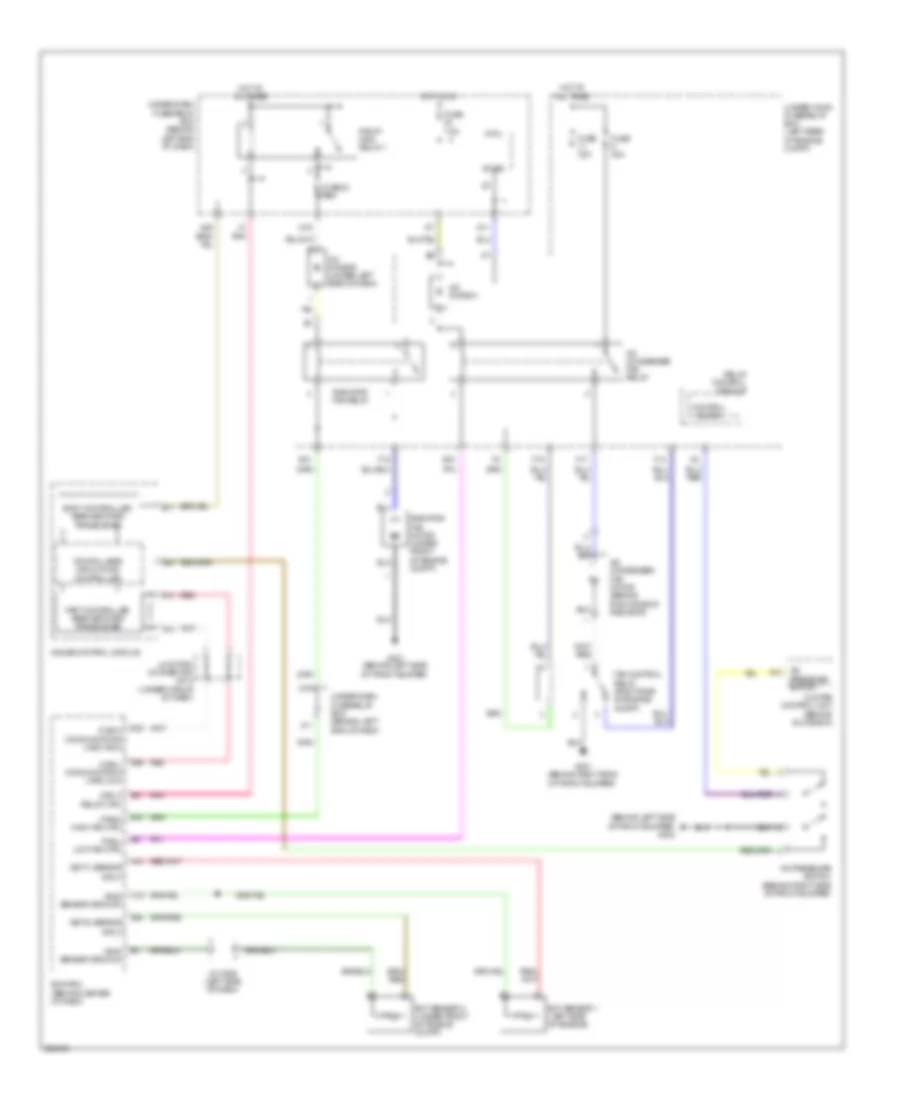
COOLING FAN
Cooling Fan Wiring Diagram for Acura TL 2007
List of elements for Cooling Fan Wiring Diagram for Acura TL 2007:
- (behind left side of front bumper) g302
- (canh) communication line (high)
- (canl) communication line (low)
- (ect1) sensor
- (ect2) sensor
- (sg2) sensor ground
- (sg4) sensor ground
- A/c condenser fan motor (behind right side of radiator)
- A/c condenser fan relay
- A/c diode a
- A/c diode b (under left side of dash)
- A/c pressure switch
- A/c pressure switch (behind right side of front bumper)
- A13
- A14
- A22
- B-can
- B10 (fanh) high fan ctrl
- B11
- B24
- Body controller area network transceiver
- C12
- Climate control unit (behind glove box)
- Control block
- Cpu/fail safe circuit/can controller
- D11
- D15
- D16
- E10
- E14
- E15
- E26
- E5 (mrly) relay ctrl
- E6 (fanl) low fan ctrl
- Ecm/pcm (behind center of dash)
- Ect sensor 1 (left side of engine)
- Ect sensor 2 (under front of engine compt)
- F14
- F15
- F17
- F19
- Fan control relay (right side of engine compt)
- Fast controller area network transceiver
- Fuse 23 7.5a
- Fuse 30a
- Fuse 7.5a
- G201 (behind right side of front bumper)
- G301 (behind left side of front bumper)
- Gauge control module
- Hot at all times
- Hot in on
- Input
- J/c c508 (left side of dash)
- Junction connector c512 (under middle of dash)
- Micu
- Pgm-fi main relay 1
- Pnk
- Radiator fan motor (under front of engine compt)
- Radiator fan relay
- Red
- Relay control module
- Under-dash fuse/relay box (behind left end of dash)
- Under-hood fuse/relay box (left rear of engine compt)
- X1 pnk
- X11
 Čeština
 Dansk
Dansk Deutsch
 Ελληνικά
 English
 English
 Suomi
Suomi Français
 Français
 עברית
עברית Hrvatski
 Magyar
 Italiano
 日本語
日本語 한국어
한국어 Nederlands
 Polski
 Português
 Português
 Română
 Русский
 Slovenčina
 Slovenščina
 Svenska
 Türkçe
 中文 (中国)
 Español