CRUISE CONTROL
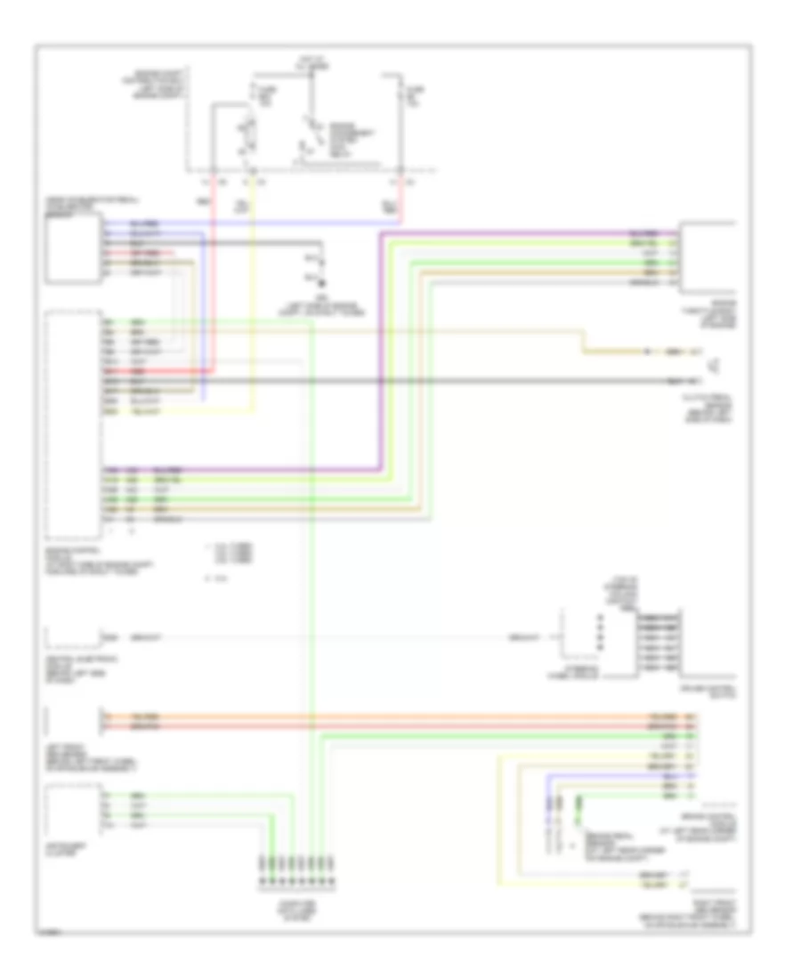
Cruise Control Wiring Diagram for Volvo V70 2005
List of elements for Cruise Control Wiring Diagram for Volvo V70 2005:
- (near accelerator pedal) accelerator sensor
- (top of steering column) contact reel
- 2.4l
- 2.4l turbo,
- 2.5l turbo, 2.9l turbo
- A19
- A20
- A25
- A35
- A36
- A43
- A59
- B11
- B13
- B15
- B17
- B25
- B38
- Brake control module (at left rear corner of engine compt)
- Brake pedal sensor (at left rear corner of engine compt)
- Central electronic module (behind left side of dash)
- Clutch pedal sensor (behind left side of dash)
- Computer data lines system
- Cruise control switch
- D58
- Engine
- Engine compt distribution box (left side of engine compt)
- Engine control module (at right side of engine compt, forward of strut tower)
- Engine throttle body (left side of engine)
- Fuse b23 10a
- Fuse b8 10a
- G93 (left side of engine compt, on strut tower)
- Hot at all times
- Instrument cluster
- Left front abs sensor (behind left front wheel, on spindle/hub assembly)
- Management system main relay
- Nca
- Red
- Right front abs sensor (behind right front wheel, on spindle/hub assembly)
- Steering wheel module
 Čeština
 Dansk
Dansk Deutsch
 Ελληνικά
 English
 English
 Suomi
Suomi Français
 Français
 עברית
עברית Hrvatski
 Magyar
 Italiano
 日本語
日本語 한국어
한국어 Nederlands
 Polski
 Português
 Português
 Română
 Русский
 Slovenčina
 Slovenščina
 Svenska
 Türkçe
 中文 (中国)
 Español