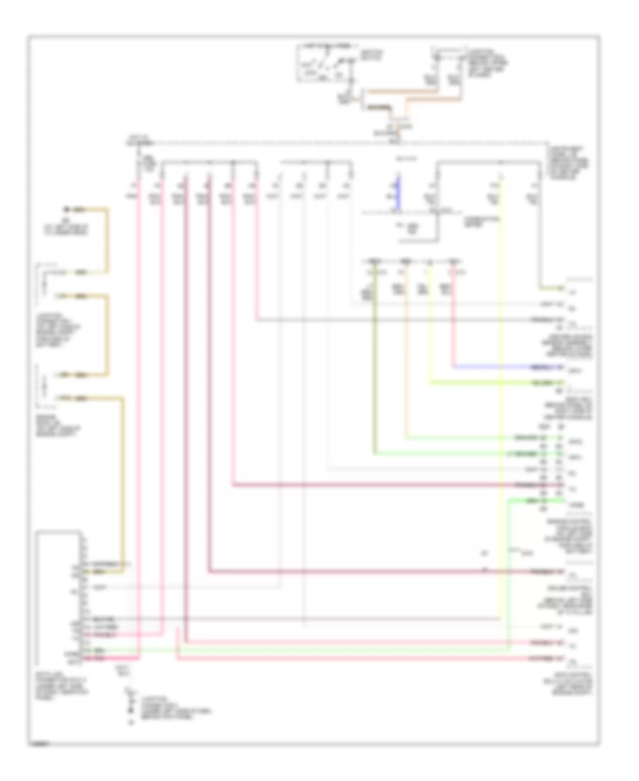
COMPUTER DATA LINES
Computer Data Lines Wiring Diagram for Toyota Celica GT 2005
List of elements for Computer Data Lines Wiring Diagram for Toyota Celica GT 2005:
- A/b
- Acc
- Bat
- Body ecu (behind panel on right side of center console)
- C12
- C13
- Center air bag sensor assembly (behind lower center of dash)
- Combination meter
- Cruise control ecu (behind left side of dash, near base of "a" pillar)
- D/g
- Data link connector (dlc) 3 (under left side of dash, near kick panel)
- Ed (at left side of cylinder head)
- Engine control module (ecm) (on left side of engine compt, forward of battery)
- Engine room j/b (on left side of engine compt)
- F13
- F18
- Forward of battery)
- Gts
- Hot at all times
- Ignition switch
- Instrument panel j/b (behind panel on right side of center console)
- Junction connector 1 (on left side of engine compt,
- Junction connector 3 (under left side of dash, behind kick panel)
- Junction connector 6 (behind upper left center of dash)
- Lock
- Mpx+
- Mpx-
- Mpx1
- Mpx2
- Obd fuse 7.5a
- Off
- Pnk
- Sil
- Skid control ecu w/ actuator (left rear of engine compt)
- Srs ind
- Start
- Tx+
- Wfse
 Čeština
 Dansk
Dansk Deutsch
 Ελληνικά
 English
 English
 Suomi
Suomi Français
 Français
 עברית
עברית Hrvatski
 Magyar
 Italiano
 日本語
日本語 한국어
한국어 Nederlands
 Polski
 Português
 Português
 Română
 Русский
 Slovenčina
 Slovenščina
 Svenska
 Türkçe
 中文 (中国)
 Español