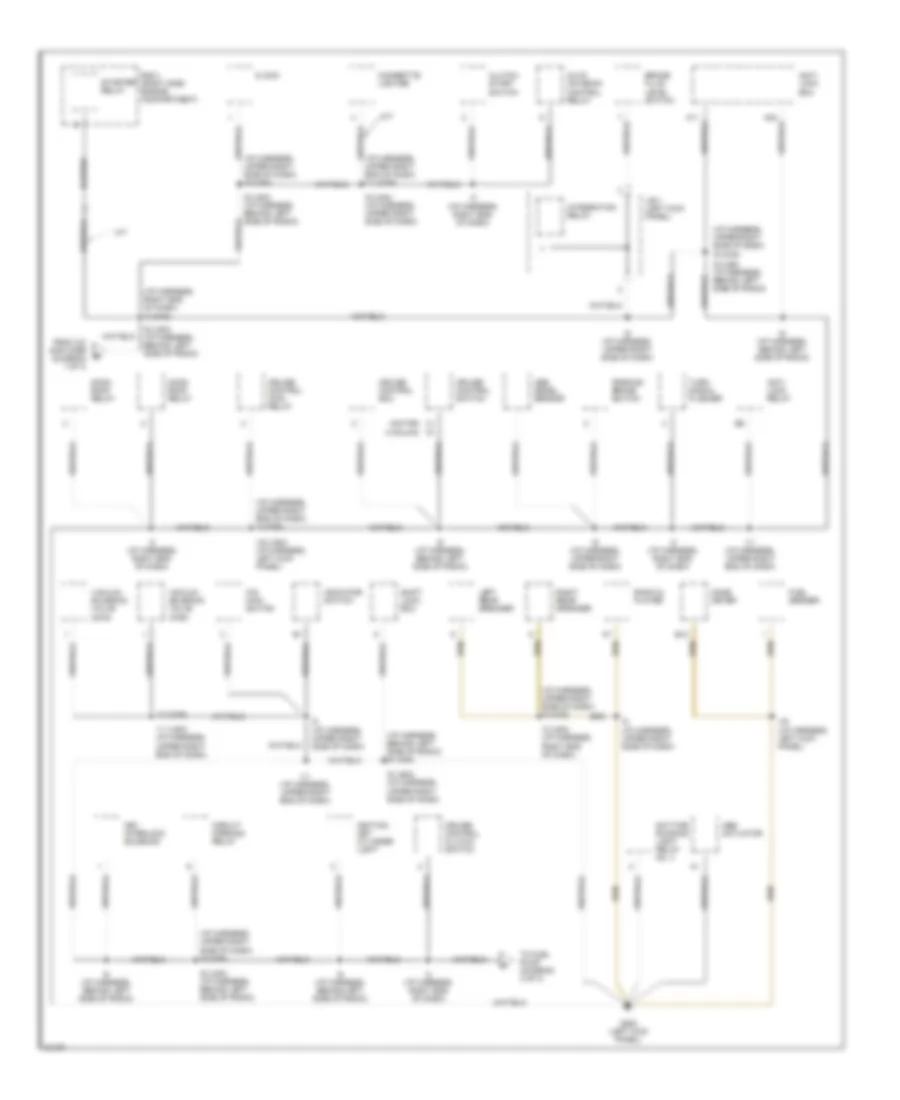
GROUND DISTRIBUTION
Ground Distribution Wiring Diagram (1 of 3) for Toyota 4Runner SR5 1995
 https://portal-diagnostov.com/license.html
Automotive Electricians Portal FZCO
Automotive Electricians Portal FZCO
https://portal-diagnostov.com/license.html
https://portal-diagnostov.com/license.html
Automotive Electricians Portal FZCO
Automotive Electricians Portal FZCO
List of elements for Ground Distribution Wiring Diagram (1 of 3) for Toyota 4Runner SR5 1995:
- (beside r/b 2) r/b 4
- (i/p harness, behind left side of radio) i6 (can)
- (i/p harness, upper right end of dash) i11 (can)
- (i/p harness, upper right end of dash) i12 (can)
- (i/p harness, upper right side of dash i9 (can)
- (right kick panel) r/b 3
- (right side of engine compartment) r/b 2
- 2.4l
- 2wd a/t
- 3.0l
- 4wd a/t
- 4wd only
- A/c amplifier
- A/c condenser fan relay #1
- A/c condenser fan relay #2
- A/c switch
- A/c thermistor
- A17
- A18
- B10
- B11 (body harness, behind right rear comb light)
- Blower resistor
- C10
- C11
- C13
- C26
- Canada only
- Comb meter
- D13
- D24
- D26
- Data link connector 1
- Daytime running light relay
- Daytime running light resistor
- Dimmer switch
- E10 (engine harness, top right of engine)
- E12 (engine harness, top rear of engine)
- E13
- E14
- E25 (engine harness, top of engine)
- E26
- E3 (engine harness, front of engine compartment above grille opening)
- Efi main relay
- Except 4wd a/t
- Front heater relay
- G100 (front of left fender)
- G108 (left side of radiator)
- G117 (right rear of engine, on camshaft bearing cap)
- G120 (right side of engine, on intake manifold)
- G203 (right kick panel)
- G905 (under right rear pillar)
- Glove box light switch
- Heated oxygen sensor (main)
- Heater blower switch
- I10 (i/p harness, right side of dash)
- I11 (i/p harness, upper right end of dash)
- I11 (usa) (i/p harness, upper right end of dash)
- I15 (i/p harness, right kick panel)
- I16 (i/p harness, left kick panel)
- I3 (i/p harness, upper left side of dash)
- I6 (i/p harness, behind left side of radio)
- I6 (usa) (i/p harness, behind left side of radio
- I9 (i/p harness, upper right side of dash)
- I9 (usa) (i/p harness, upper right side of dash)
- Left front parking light
- Left front turn signal light
- Light control switch
- Main heated oxygen sensor
- Noise filter
- Of rear apron)
- Only
- Powertrain control module
- Rear heater
- Rear heater relay
- Rheostat
- Right front clearance light
- Right front turn signal light
- Right rear comb light
- Side of dash)
- Sub heated oxygen sensor
- To g904 (diagram 3 of 3)
- To starter relay (diagram 2 of 3)
- Volume air flow meter
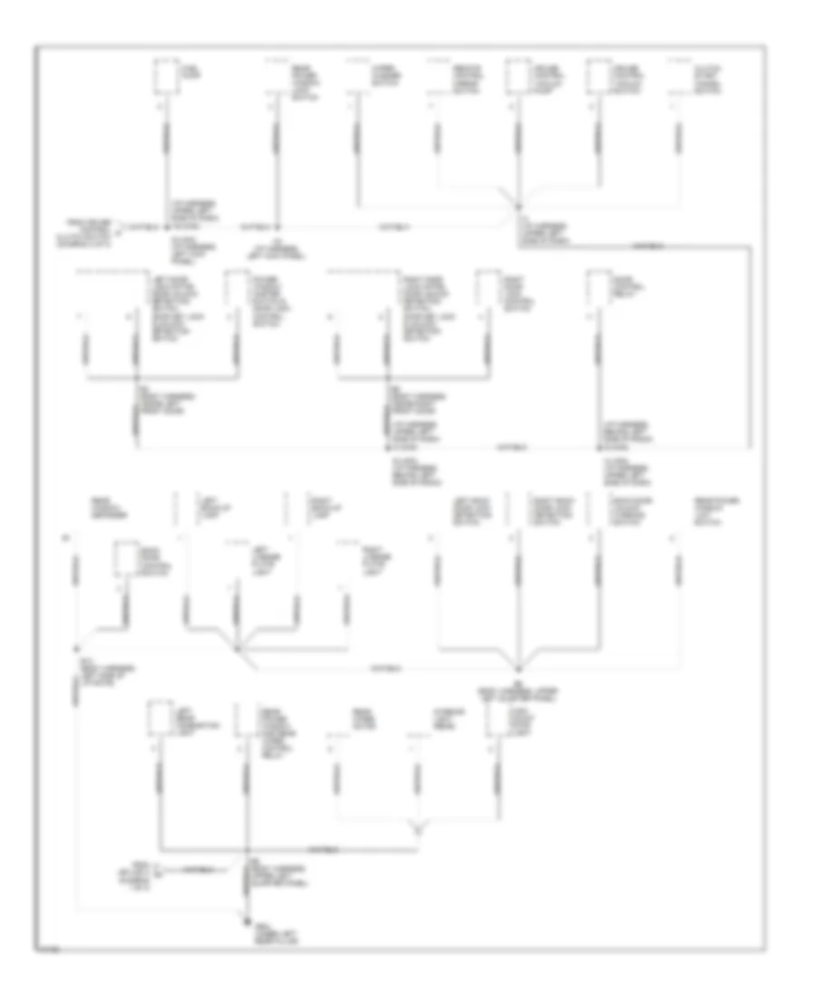
Ground Distribution Wiring Diagram (2 of 3) for Toyota 4Runner SR5 1995
List of elements for Ground Distribution Wiring Diagram (2 of 3) for Toyota 4Runner SR5 1995:
- (i/p harness, behind left side of radio) i6 (can)
- (i/p harness, right end of dash) i3 (can)
- (i/p harness, upper right end of dash) i11 (can)
- (i/p harness, upper right end of dash) i3 (can)
- (i/p harness, upper right side of dash)
- (i/p harness, upper right side of dash) i9 (can)
- (motor)
- (vacuum)
- A/t
- A11
- A24
- Abs actuator
- Abs decel sensor
- Anti- lock ecu
- Anti- lock relay
- Auto antenna control relay
- B12
- Brake fluid level switch
- Cigarette lighter
- Circuit opening relay
- Clock
- Clutch start switch
- Comb meter
- Cruise control clutch switch
- Cruise control ecu
- Cruise control main relay
- Cruise control switch
- Daytime running light relay no. 4
- From a/c amplifier (diagram 1 of 3)
- Fuel sender
- G200 (left kick panel)
- I11 (i/p harness, upper right end of dash)
- I11 (usa) (i/p harness, upper right end of dash)
- I12 (can)
- I16 (i/p harness, left kick panel)
- I16 (usa) (i/p harness, left kick panel)
- I3 (i/p harness, right end of dash)
- I3 (usa) (i/p harness, right end of dash)
- I6 (i/p harness, behind left side of radio)
- I6 (usa) (i/p harness, behind left side of radio)
- I8 (i/p harness, upper right side of dash)
- I9 (can)
- I9 (i/p harness, upper right side of dash)
- I9 (usa) (i/p harness, upper right side of dash)
- Ignition key cylinder light
- Indicator switch
- Integration relay
- J/b 1 (left kick panel)
- Key interlock solenoid
- Left rear speaker
- M/t
- Moon roof relay
- O/d main switch
- Parking brake switch
- R/b 2 (right side engine compartment)
- Radio & player
- Right rear speaker
- Shift lock ecu
- Starter relay
- To fuel pump (diagram 3 of 3)
- Turn signal flasher
- Vacuum solenoid valve (2wd)
- Vacuum solenoid valve (4wd)
Ground Distribution Wiring Diagram (3 of 3) for Toyota 4Runner SR5 1995
List of elements for Ground Distribution Wiring Diagram (3 of 3) for Toyota 4Runner SR5 1995:
- (diagram 1 of 3)
- (i/p harness, behind left side of radio)
- (i/p harness, upper left side of dash)
- B13 (body harness, left side of liftgate)
- B3 (body harness, inside left front door)
- B5 (body harness, inside right front door)
- B6 (body harness, upper left quarter panel)
- Back door control switch
- Back door unlock warning switch
- Clutch start cancel switch
- Cruise control vacuum pump
- Cruise control vacuum switch
- Door control relay
- From cruise control c clutch switch (diagram 2 of 3)
- From splice i3 a
- Fuel pump
- G904 (under left rear pillar)
- High mount stop light
- I16 (can)
- I16 (i/p harness, left kick panel)
- I3 (can)
- I3 (i/p harness, upper left side of dash)
- I3 (usa) (i/p harness, upper left side of dash)
- I6 (can)
- I6 (usa) (i/p harness, behind left side of radio)
- I6 (usa) (i/p harness, left kick panel)
- Interior light (rear)
- Left back door lock detection switch
- Left back-up lamp
- Left door lock motor, door unlock detection switch, door key lock & unlock detection switch
- Left license plate light
- Left rear combination light
- Power window master switch & door lock control switch
- Rear power window and rear wiper control relay
- Rear power window limit switch
- Rear power window lock switch
- Rear window defogger
- Rear wiper motor
- Remote control mirror switch
- Right back door lock detection switch
- Right back-up lamp
- Right door lock control switch
- Right door lock motor, door unlock detection switch, door key lock & unlock detection switch
- Right license plate light
- Wiper/ washer switch

 Čeština
 Dansk
Dansk Deutsch
 Ελληνικά
 English
 English
 Suomi
Suomi Français
 Français
 עברית
עברית Hrvatski
 Magyar
 Italiano
 日本語
日本語 한국어
한국어 Nederlands
 Polski
 Português
 Português
 Română
 Русский
 Slovenčina
 Slovenščina
 Svenska
 Türkçe
 中文 (中国)