GROUND DISTRIBUTION
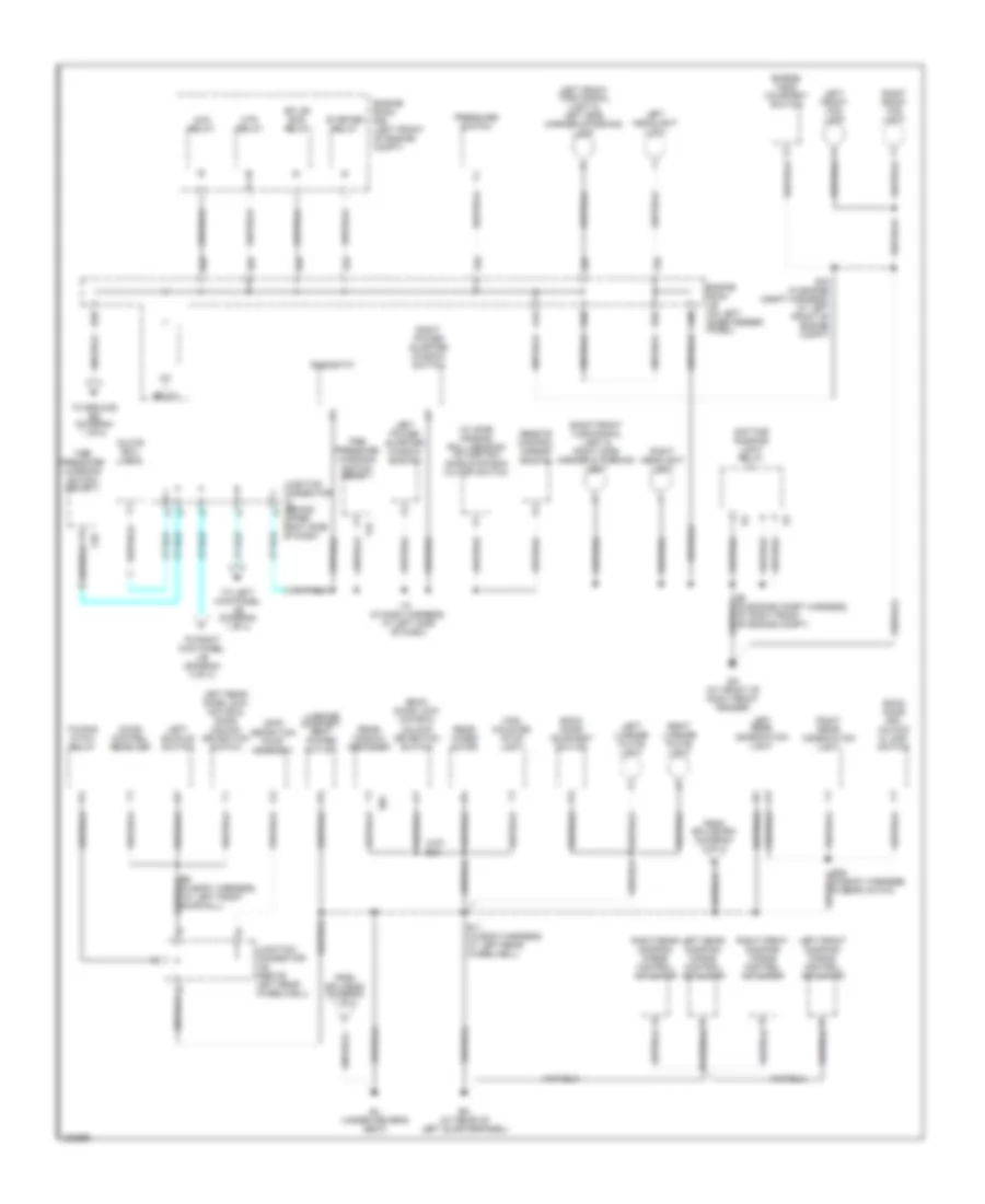
Ground Distribution Wiring Diagram (1 of 4) for Toyota Land Cruiser 2006
 https://portal-diagnostov.com/license.html
Automotive Electricians Portal FZCO
Automotive Electricians Portal FZCO
https://portal-diagnostov.com/license.html
https://portal-diagnostov.com/license.html
Automotive Electricians Portal FZCO
Automotive Electricians Portal FZCO
List of elements for Ground Distribution Wiring Diagram (1 of 4) for Toyota Land Cruiser 2006:
- 1 of 4)
- A/c control assembly
- A/f htr relay
- A37
- A38
- A40
- A41
- A42
- A47
- A53
- Abs & ba & trac & vsc actuator
- Abs & ba & trac & vsc ecu
- Acc relay
- Air injection control driver
- Air vent mode control servo motor
- Auto antenna control relay
- B13
- B2 (in body harness, in left front door)
- B27 (in body harness, bottom of driver's seat)
- B4 (body harness, at left front door sill)
- B7 (in body harness, at front of roof)
- Body ecu
- C11
- C17
- Center cluster integration panel
- Cigarette lighter
- Combination switch
- D18
- D22
- D23
- Damping mode select switch & height control switch
- Data link connector
- Defog relay
- Driver's power seat control switch
- Driver's seat cushion seat heater
- Driver's seat lumbar support control switch
- E14
- E14 (in engine compt harness, at left rear of engine compt)
- E18
- E34
- Ee (at left front fender apron)
- Electronically controlled transmission pattern select switch
- Engine control module
- Engine room r/b 8
- From engine room j/b (diagram 2 of 4)
- From j/b (diagram 1 of 4)
- From j/b (diagram b
- From j/c 12 (diagram 2 of 4)
- Front interior light & rear personal light
- Front personal light
- Front power outlet
- Fuel pump & fuel sender
- I2 (in dash harness, at left kick panel)
- Ign 2 relay
- Inner mirror
- J/b (behind center of dash)
- Junction connector (behind upper center of dash)
- K33
- Key interlock solenoid
- L11
- L14
- Left door key lock & unlock switch
- Left front door lock motor & door unlock detection switch
- Left kick panel j/b (left kick panel)
- Left rear power window control switch
- Left remote control mirror
- Left vanity light
- M10
- Moon roof control ecu
- Moon roof control switch
- Multi- display shield
- Nca
- Overhead j/b
- Power window master switch
- Q20
- Q23
- Q43
- Rear heater power transistor
- Right kick panel j/b (right kick panel)
- Right vanity light
- S20
- Shift lock control ecu
- Suspension control ecu
- Theft deterrent ecu
- To ground bj (diagram 2 of 4)
- To j/b (diagram 1 of 4)
- To j/b (diagram 1 of 4)
- Translate ecu
- Transponder key computer
- Unlock warning switch
- W/ navigation
- W/o navigation
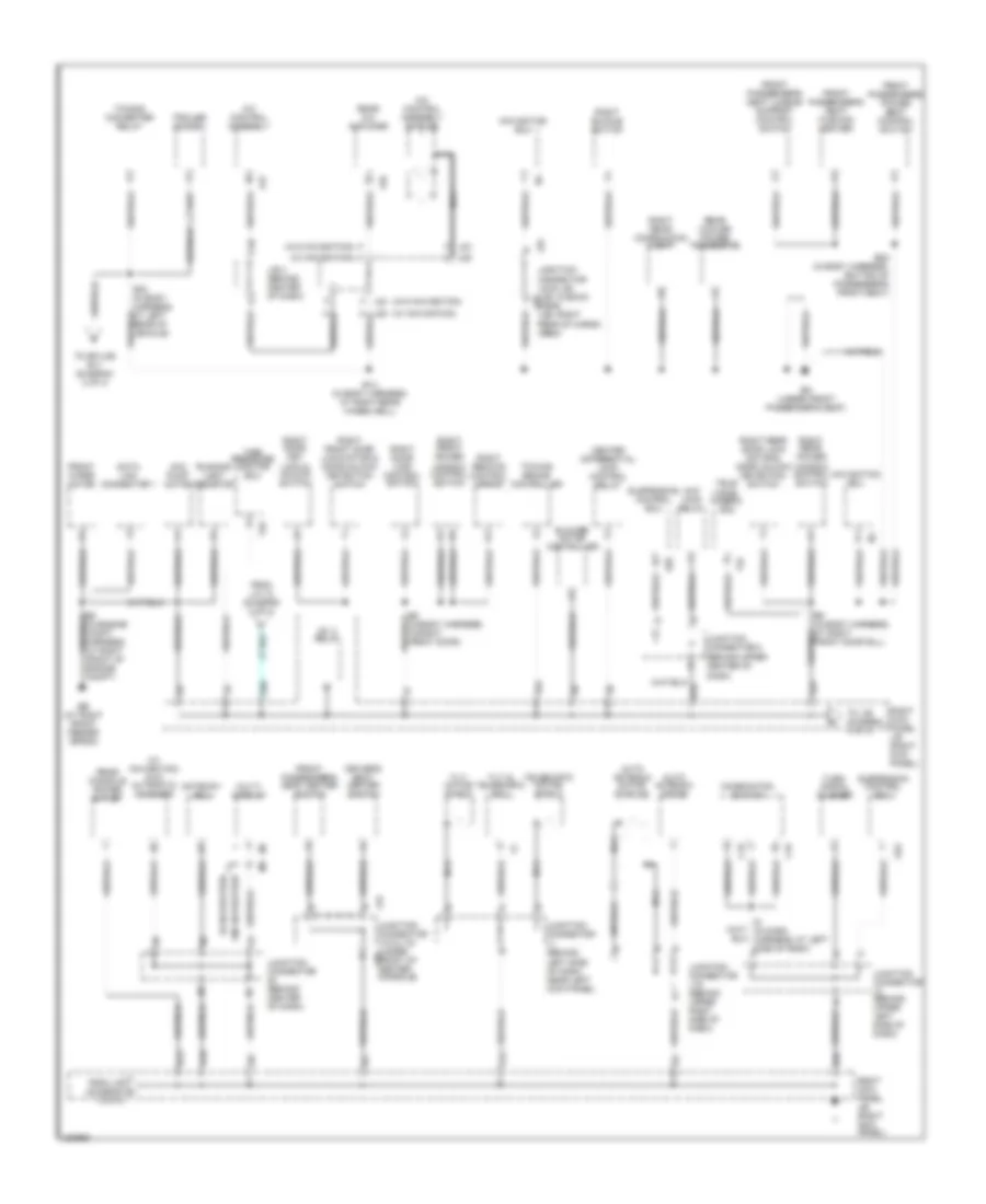
Ground Distribution Wiring Diagram (2 of 4) for Toyota Land Cruiser 2006
List of elements for Ground Distribution Wiring Diagram (2 of 4) for Toyota Land Cruiser 2006:
- (w/ side air bag) roll sensing of curtain shield air bag cutoff switch
- A24
- A30
- A34
- A37
- A43
- Ahc relay
- B11 (in body harness, at left rear wheelwell)
- B26 (in body harness, in rear hatch)
- B35
- B39
- B40
- B42
- B43
- B44
- B56
- B6 (in body harness, (at left front door sill)
- Back door courtesy switch
- Back door key unlock & lock switch
- Back door lock motor & unlock detection switch
- Bj (under driver's seat)
- Bm (at rear of left quarterpanel)
- Daytime running light relay
- Door control receiver
- E15 (in engine compt harness, at left front of engine compt)
- E2 (in engine compt harness, at right front of engine compt)
- Ea (at front of right front fender)
- Efi or ecd relay
- Engine hood courtesy switch
- Engine room j/b (on left inner fender panel)
- Engine room r/b (left front of engine compt)
- From splice b16 (diagram 3 of 4)
- From splice b4 (diagram 1 of 4)
- Glove box light
- High mounted stop light
- Htr relay
- I18 (in dash harness, at left side of dash)
- Ig1 relay
- Junction connector (behind upper right side of dash)
- Junction connector j22 (above left rear wheelwell)
- Leak detection pump assembly
- Left buckle switch
- Left front damping force control actuator
- Left front fog light
- Left front turn signal light & left side marker & parking light
- Left headlight (low)
- Left license plate light
- Left power quarter window switch
- Left rear combination light
- Left rear damping force control actuator
- Left rear door lock motor & door unlock detection switch
- Luggage compart- ment power outlet
- Pressure switch
- R29
- Rear window defogger
- Rear wiper motor
- Remote control mirror switch
- Rheostat
- Right front damping force control actuator
- Right front fog light
- Right front turn signal light & right side marker & parking light
- Right headlight (low)
- Right license plate light
- Right power quarter window switch
- Right rear combination light
- Right rear damping force control actuator
- Starter relay
- T27
- T28
- Tire pressure warning switch (reset)
- Tire pressure warning switch (select)
- To ground ee (diagram 1 of 4)
- To left kick panel j/b (diagram 1 of 4)
- To right kick panel j/b (diagram 3 of 4)
- Towing hitch relay
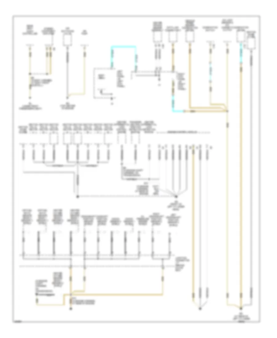
Ground Distribution Wiring Diagram (3 of 4) for Toyota Land Cruiser 2006
List of elements for Ground Distribution Wiring Diagram (3 of 4) for Toyota Land Cruiser 2006:
- (behind upper center of dash)
- (w/ navigation)
- (w/ navigation) dvd automatic changer
- (w/o navigation)
- 3 of 4)
- A/c control assembly
- A/c control assembly shields
- A32
- A47
- Ahc main relay
- Ahc pump motor
- Auto antenna motor
- Auto antenna motor shields
- B14 (in body harness, at right rear wheelwell)
- B28 (in body harness, bottom of passenger's front seat)
- B8 (in body harness, in right front door)
- B9 (in body harness, at right front door sill)
- Bk (under front passenger's seat)
- Blower motor controller
- C16
- C19
- Center differential lock control relay
- Combination switch
- D10
- D18
- D23
- D42
- Data link connector 1
- Driver's seat heater switch
- E34
- E35
- E5 (in engine compt harness, at right front of engine compt)
- Eb (at right front fender apron)
- F (w/o navigation)
- F j23
- F10
- From j/b (diagram h
- From j/c 12 (diagram 2 of 4)
- Front passenger's power seat control switch
- Front passenger's seat cushion heater
- Front passenger's seat heater switch
- Front passenger's seat lumbar support control switch
- Front wiper motor
- Gateway ecu
- H (w/ navigation)
- H j25
- I9 (in dash harness, at left side of dash)
- Ig1 3 relay
- J/b (right kick panel)
- J/b 4 (behind center of dash)
- J19
- J23 f
- J25
- Junction connector (behind center of dash)
- Junction connector 8
- Junction connector j1 (behind
- Junction connector j16 (behind upper right side of dash)
- Junction connector j18 & j19 (under j18 front of center console)
- Junction connector j23 & j25 (j23: in back j25 door) (j25: right rear of cargo area)
- Junction connector j3 (behind upper left side of dash)
- K31
- Left side of dash, near left kick panel)
- Multi- display
- Navigation ecu
- Nca
- Q58
- Rear a/c amplifier
- Rear console power outlet
- Rear cooler power transistor
- Rear of vehicle)
- Right buckle switch
- Right door key lock & unlock switch
- Right door lock control switch
- Right front door lock motor & door unlock detection switch
- Right front power window control switch
- Right kick panel
- Right kick panel j/b (right kick panel)
- Right rear combination light
- Right rear door lock motor & door unlock detection switch
- Right rear power window control switch
- Right remote control mirror
- Running light resistor
- S20
- S22
- Suspension control ecu
- T22
- T25
- Tele- vision camera ecu
- Telescopic motor shield
- Tilt motor shield
- Tilt & telescopic ecu
- Tire pressure monitor ecu
- To j/b (diagram 3 of 4)
- To splice b11 (diagram 2 of 4)
- Towing brake controller
- Towing converter relay
- Trailer socket
- Turn signal flasher
- W/ navigation
- W/o navigation
Ground Distribution Wiring Diagram (4 of 4) for Toyota Land Cruiser 2006
List of elements for Ground Distribution Wiring Diagram (4 of 4) for Toyota Land Cruiser 2006:
- (at rear of left cylinder head)
- (in engine compt harness, on transmission) e8
- (in engine harness, at rear of engine)
- A/c lock sensor & a/c magnetic clutch
- Air fuel ratio sensor (bank 1 sensor 1) shield
- Air fuel ratio sensor (bank 2 sensor 1) shield
- Air pump
- Air switching valve
- B9 (in body harness, at right front door sill)
- Bl (under front passenger's seat)
- Body ecu
- C15
- C18
- C26
- Camshaft position sensor shield
- Center air bag sensor assembly
- Center differential lock control motor
- Center differential lock detection switch
- Combination meter
- Combination switch
- Crankshaft position sensor shield
- Data link connector 3
- E10
- E10 (in engine harness, at rear of engine)
- E9 (in engine compt harness, on transmission)
- En (top center of engine)
- Engine control module
- Eo (front of left cylinder head)
- Heated oxygen sensor (bank 1
- Heated oxygen sensor (bank 1 sensor 2) shield
- Heated oxygen sensor (bank 2 sensor 2) shield
- Ignition coil & ignitor
- Ignition noise filter
- Junction connector j17 (behind glove box)
- Knock sensor 1 shield
- Knock sensor 2 shield
- Left crankshaft position sensor 2 shield
- Left kick panel j/b (left kick panel)
- Nca
- Oil pressure sender shield
- Q14
- Q40
- Rear seat audio controller
- Right crankshaft position sensor 2 shield
- Right kick panel j/b (right kick panel)
- Sensor 2)
- Shield
- Stereo component amplifier
- Transfer neutral position detection switch
- Vehicle speed sensor (combination meter)

 Čeština
 Dansk
Dansk Deutsch
 Ελληνικά
 English
 English
 Suomi
Suomi Français
 Français
 עברית
עברית Hrvatski
 Magyar
 Italiano
 日本語
日本語 한국어
한국어 Nederlands
 Polski
 Português
 Português
 Română
 Русский
 Slovenčina
 Slovenščina
 Svenska
 Türkçe
 中文 (中国)