PASSIVE RESTRAINTS
Passive Restraints Wiring Diagram for Toyota Celica GT 2004
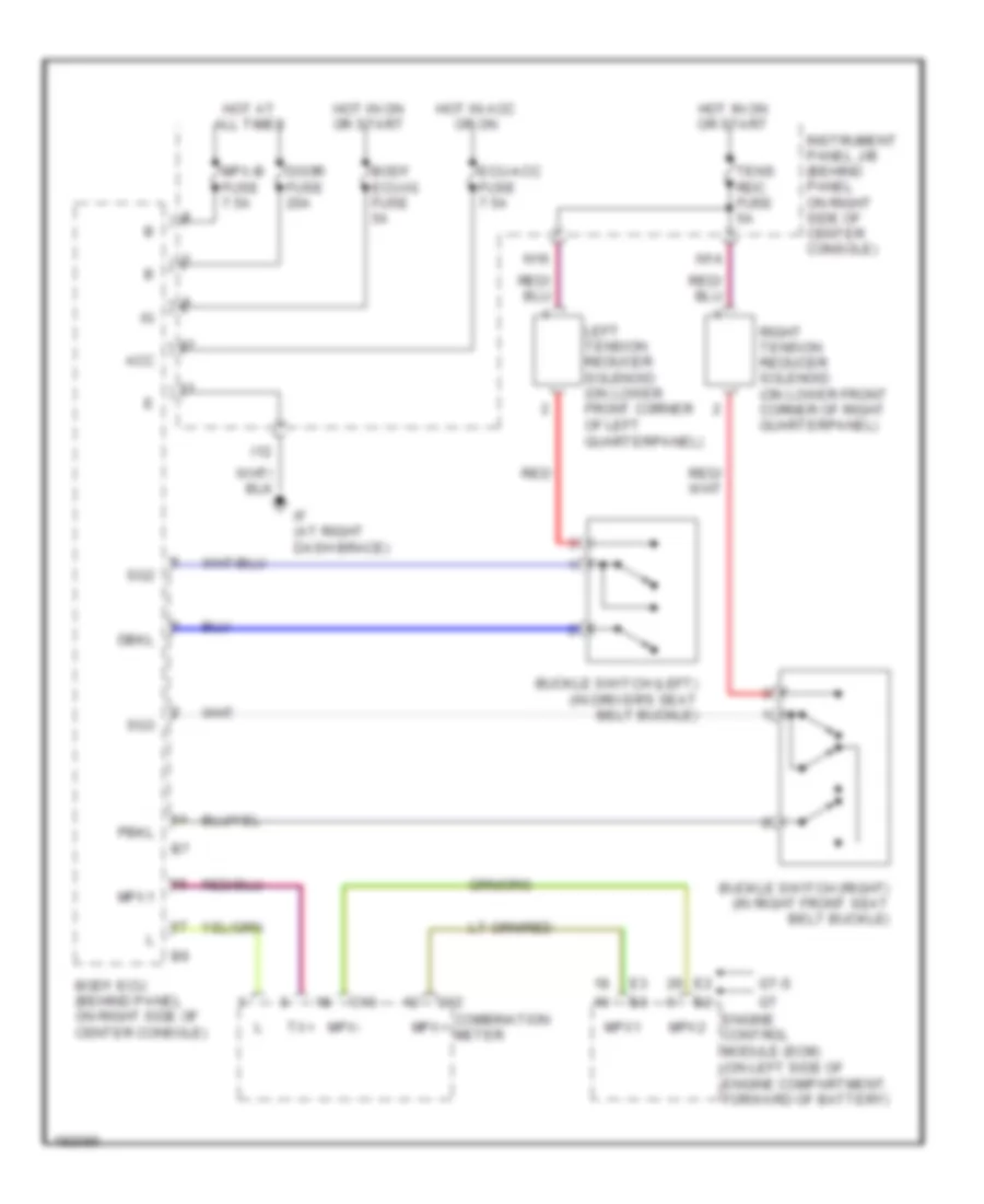
List of elements for Passive Restraints Wiring Diagram for Toyota Celica GT 2004:
- Acc
- Body ecu (behind panel on right side of center console)
- Body ecu-ig fuse 5a
- Buckle switch (left) (in driver's seat belt buckle)
- Buckle switch (right) (in right front seat belt buckle)
- C12
- C13
- Combination meter
- Dbkl
- Door fuse 20a
- Ecu-acc fuse 7.5a
- Engine control module (ecm) (on left side of engine compartment, forward of battery)
- Gt-s
- Hot at all times
- Hot in acc or on
- Hot in on or start
- I12
- If (at right dash brace)
- Instrument panel j/b (behind panel on right side of center console)
- Left tension reducer solenoid (on lower front corner of left quarterpanel)
- Mpx+
- Mpx-
- Mpx-b fuse 7.5a
- Mpx1
- Mpx2
- N14
- N16
- Pbkl
- Red
- Right tension reducer solenoid (on lower front corner of right quarterpanel)
- Sg2
- Sg3
- Tens rdc fuse 5a
- Tx+
 Čeština
 Dansk
Dansk Deutsch
 Ελληνικά
 English
 English
 Suomi
Suomi Français
 Français
 עברית
עברית Hrvatski
 Magyar
 Italiano
 日本語
日本語 한국어
한국어 Nederlands
 Polski
 Português
 Português
 Română
 Русский
 Slovenčina
 Slovenščina
 Svenska
 Türkçe
 中文 (中国)
 Español