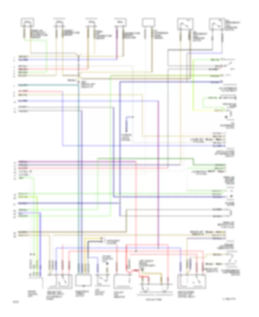
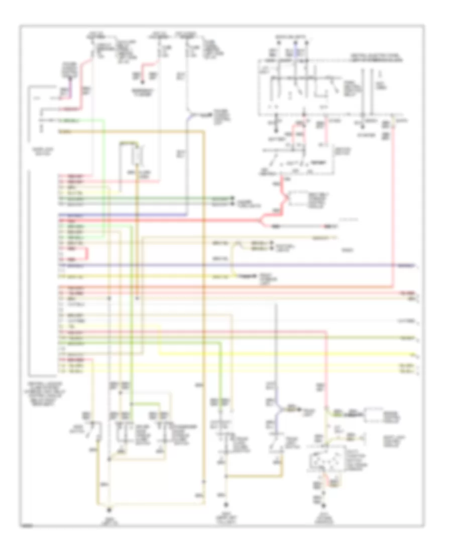
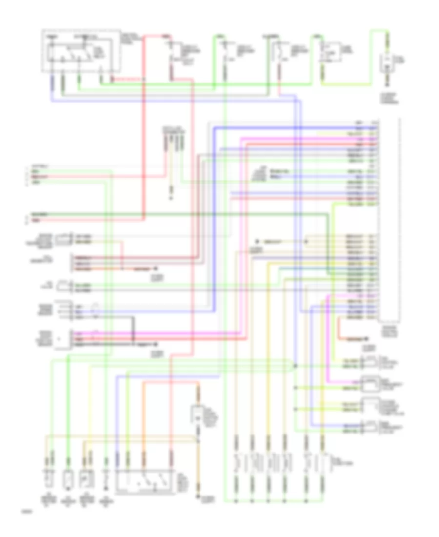
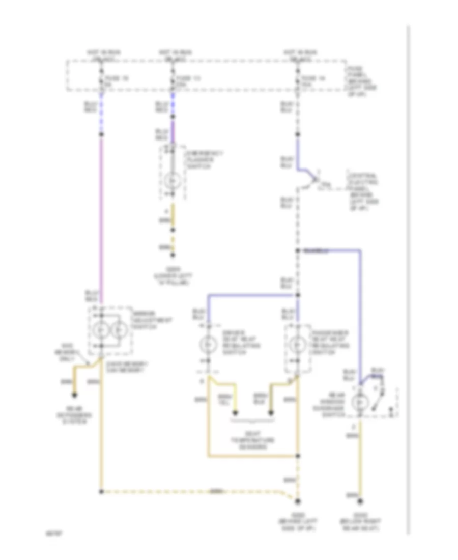
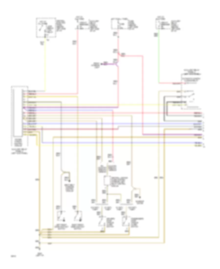
AIR CONDITIONING
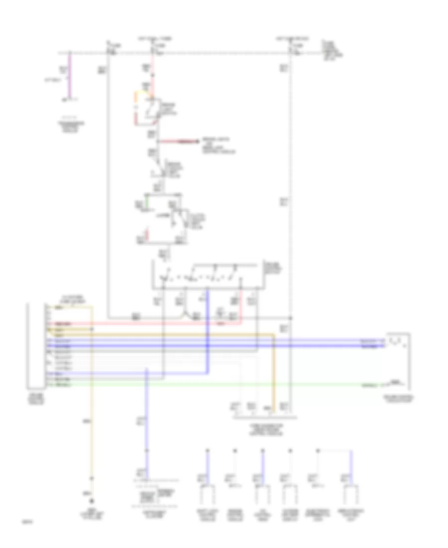
A/C-Heater System Wiring Diagram (100 CS Wiring Diagram 1 Of 2) for Audi 100 CS 1994
 https://portal-diagnostov.com/license.html
Automotive Electricians Portal FZCO
Automotive Electricians Portal FZCO
https://portal-diagnostov.com/license.html
https://portal-diagnostov.com/license.html
Automotive Electricians Portal FZCO
Automotive Electricians Portal FZCO
List of elements for A/C-Heater System Wiring Diagram (100 CS Wiring Diagram 1 Of 2) for Audi 100 CS 1994:
- (connector
- 15a
- 2-way
- A/c control unit
- Air flow flap
- Auxiliary relay panel 2
- Battery(30)
- Central flap
- Connector
- Coolant
- Data
- Defroster
- Footwell/
- Fuse
- Fuse 15 5a
- Fuse 15a
- Fuse 30a
- Fuse 5a
- Fuse 60a
- Fuse/
- G202 (behind left side of i/p)
- G203 (lower right "a" pillar)
- Hot at all times
- Hot w/ lights on
- Hot w/ load reduction relay energized (x)
- Ignition(15)
- Interior temperature fan & sensor
- Link
- Panel
- Relay
- Station 2)
- Tcm
- Temp regulator flap motor
- Valve
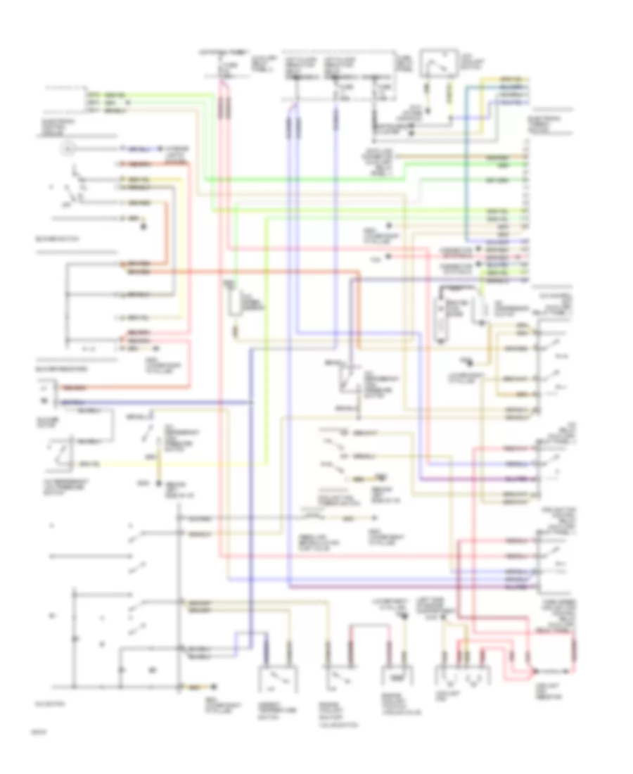
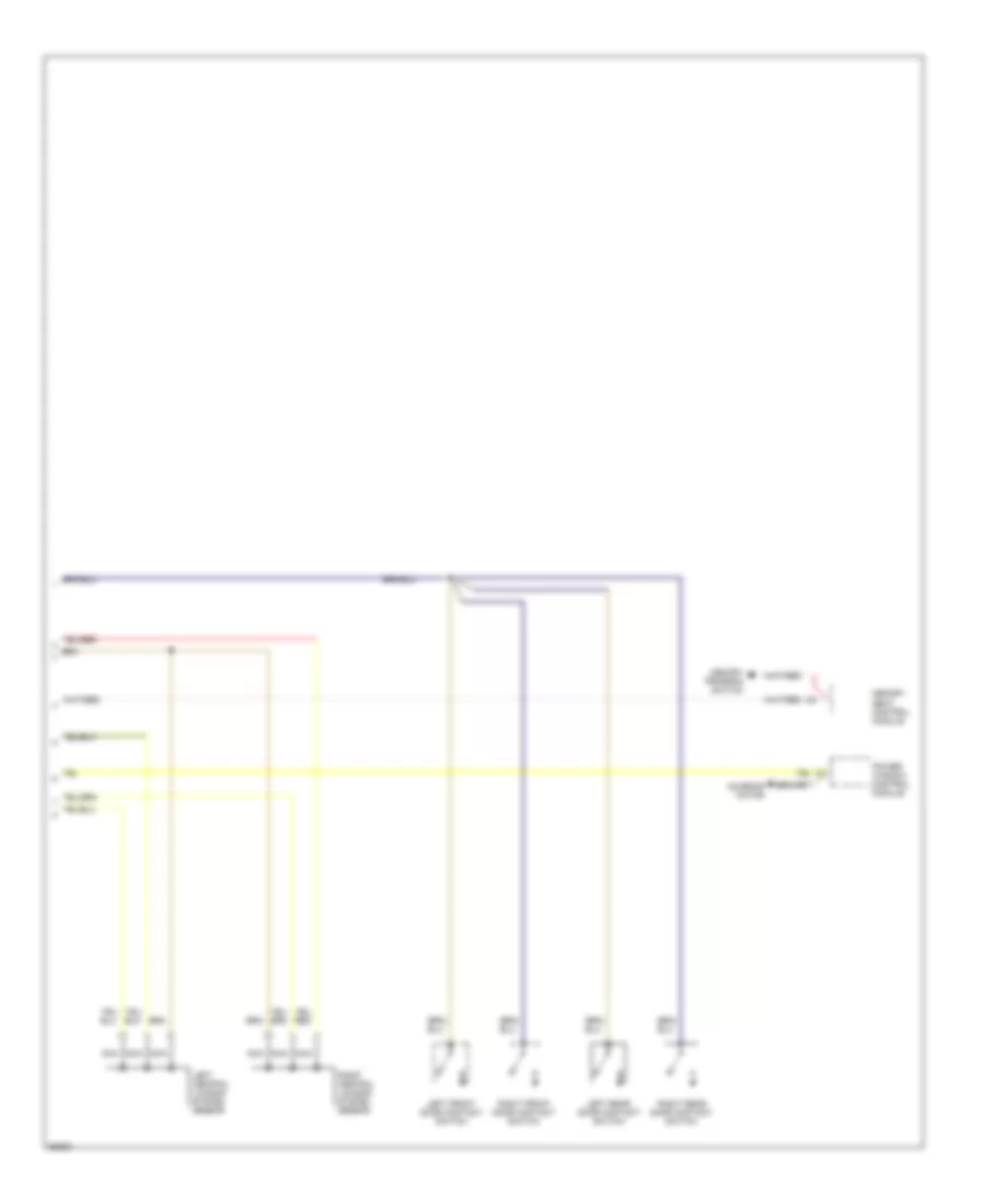
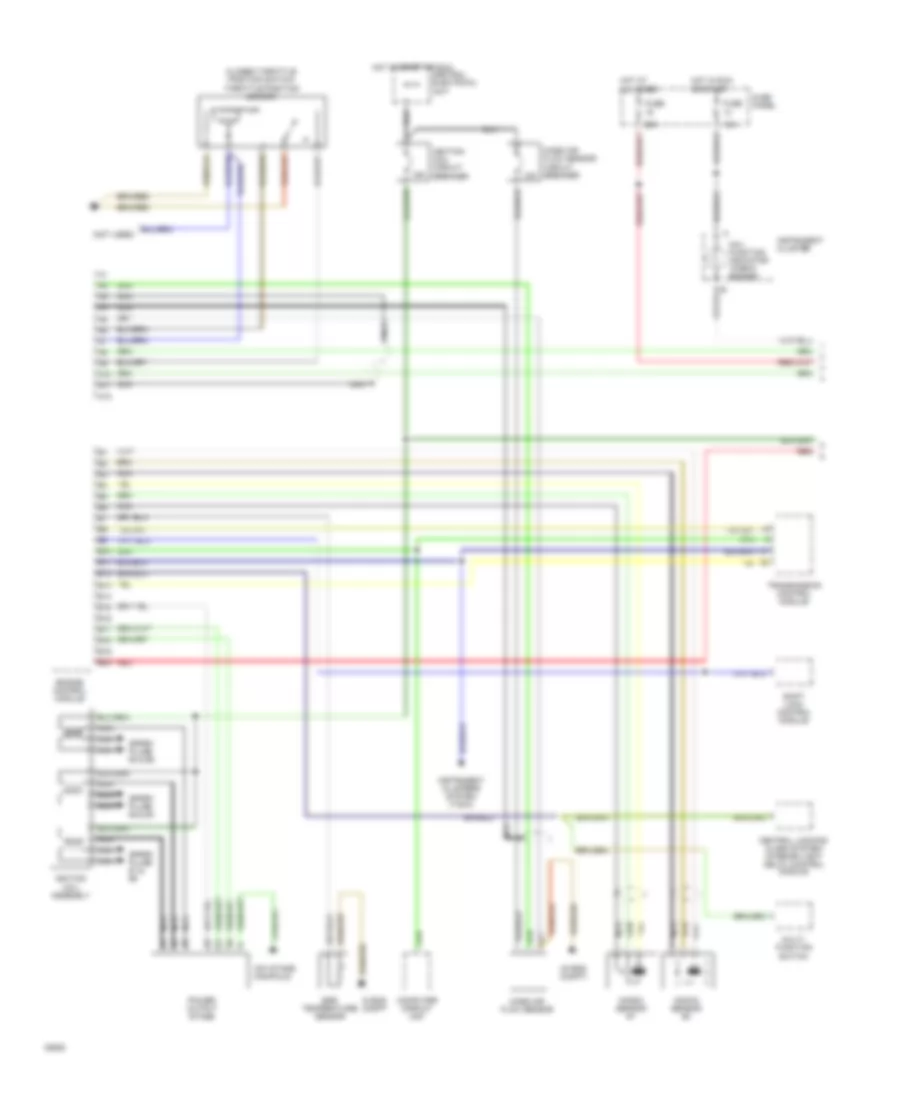
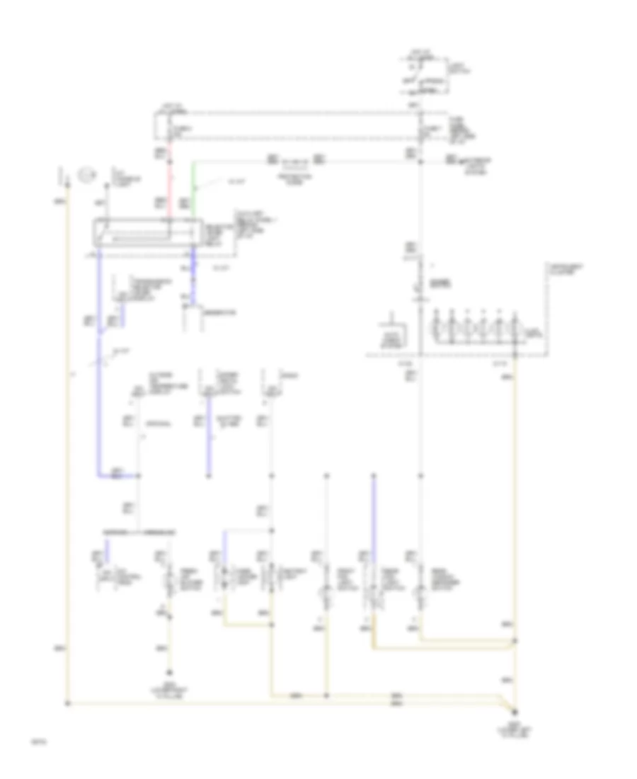
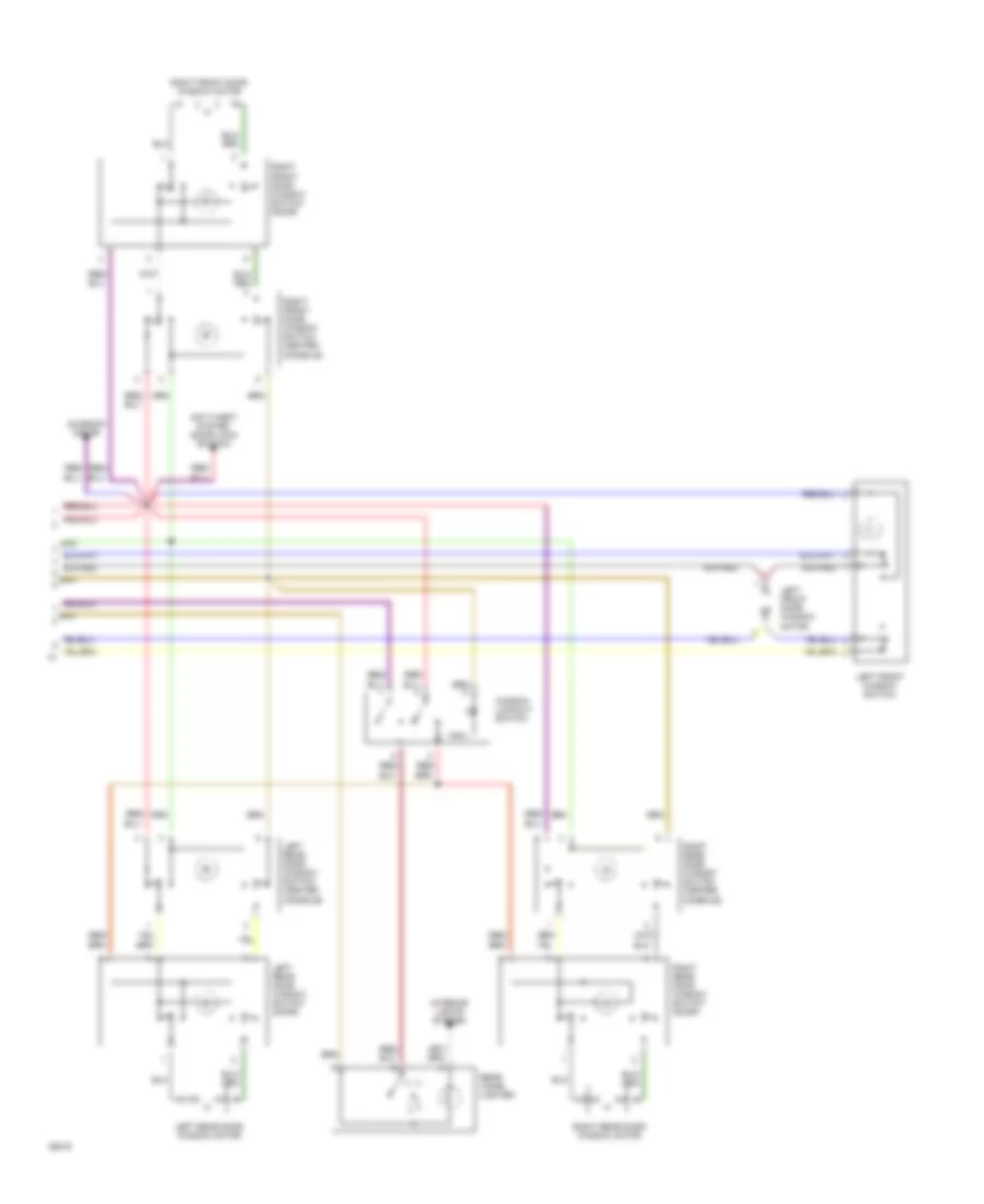
A/C-Heater System Wiring Diagram (100 CS Wiring Diagram 2 Of 2) for Audi 100 CS 1994
List of elements for A/C-Heater System Wiring Diagram (100 CS Wiring Diagram 2 Of 2) for Audi 100 CS 1994:
- (behind left side of i/p)
- (in fuse/relay panel)
- (intake manifold) g131
- (left side of engine compartment)
- (lower left "a" pillar)
- (lower right "a" pillar)
- A/c compressor
- A/c compressor clutch
- A/c compressor clutch relay
- A/c refrigerant high pressure switch
- A/c refrigerant low pressure switch
- B10
- Blower motor
- C 1995 vftc
- C10
- C11
- Coolant fan control relay
- Coolant fan control thermo switch
- Coolant fan resistor
- Coolant fans
- Digital outside air temperature display
- Electronic thermo switch
- Engine control unit
- Fresh air blower control module
- Fresh air recirculating flap valve
- Fresh air temperature sensor
- G100
- G200
- G202
- G202 (behind left side of i/p)
- G203
- Instrument cluster
- Interior lights system
- Low coolant switch
- Protection diode
- Red
- Second speed coolant fan control relay
- Speed sensor
- Temperature sensor, headliner
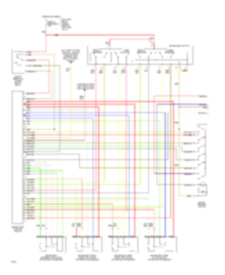
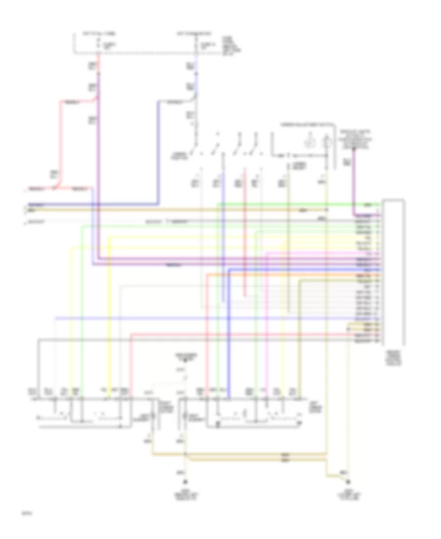
Manual A/C Wiring Diagram for Audi 100 CS 1994
List of elements for Manual A/C Wiring Diagram for Audi 100 CS 1994:
- "a" pillar)
- (behind left side of i/p)
- (connector station 2)
- (left side of engine compartment)
- (lower right
- (lower right "a" pillar)
- A/c compressor clutch
- A/c control unit (auxiliary relay panel 1)
- A/c refrigerant high pressure switch
- A/c refrigerant low pressure switch
- A/c relay (auxiliary relay panel 1)
- A/c speed sensor
- A/c switch
- Ambient temperature
- Auxiliary relay panel 2
- B10
- Blower motor
- Blower resistors
- Blower switch
- C10
- C11
- Coolant fan
- Coolant fan control relay (auxiliary relay panel 1)
- Coolant fan resistor
- Coolant fan thermo switch
- Data link connector (auxiliary relay panel 1)
- Electronic control module
- Electronic thermo switch
- Engine coolant
- Engine coolant two-way vacuum valve
- Fresh air/ recirculation flap valve
- Fuse 15a
- Fuse 30a
- Fuse 60a
- Fuse/ relay panel
- G100
- G131 (intake manifold)
- G202
- G203
- G203 (lower right "a" pillar)
- Hot at all times
- Hot w/load reduction relay energized(x)
- Ignition(15)
- Instrument cluster
- Interior
- Lights
- Low coolant switch
- Nca
- Off
- Protec- tion diode
- Red
- Shutoff
- Switch
- System
- Tcm
- Third speed coolant fan control relay (auxiliary relay panel 1)
- Valve switch
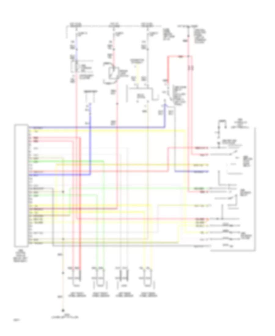
ANTI-LOCK BRAKES
Anti-Lock Brakes Wiring Diagram for Audi 100 CS 1994
List of elements for Anti-Lock Brakes Wiring Diagram for Audi 100 CS 1994:
- (below left
- (left firewall)
- (lower left "a" pillar)
- 10a
- 15a
- 21a
- Abs
- Abs combi relay (in auxiliary relay panel 2, left kick panel)
- Abs return flow pump
- Abs return flow pump relay
- Abs solenoid relay
- Abs solenoid valves
- Abs warning ind.
- All times
- Brake lamp switch
- Central electric panel (left of steering column)
- Connector station 1
- Control
- Fuse 15 5a
- Fuse 21 15a
- Fuse 9 10a
- Fuse panel (behind left side of i/p)
- G200
- Generator
- Hot at
- Hot at all times
- Hot in on or start
- Hydraulic
- Instrument cluster
- Left front wheel sensor
- Left rear wheel sensor
- Module
- Nca
- Rear seat)
- Red
- Red red
- Right front wheel sensor
- Right rear wheel sensor
- Solid state
- Unit
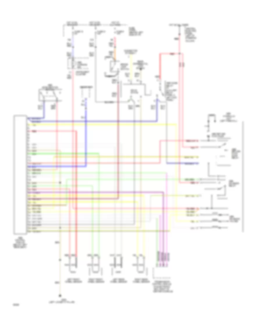
Anti-Lock Brakes Wiring Diagram, Quattro for Audi 100 CS 1994
List of elements for Anti-Lock Brakes Wiring Diagram, Quattro for Audi 100 CS 1994:
- (in electronic box, right of center console)
- (left firewall)
- (left lower "a" pillar)
- 15a
- 21a
- Abs
- Abs acceleration switch
- Abs combi relay (in
- Abs control module (below left rear seat)
- Abs return flow pump
- Abs return flow pump relay
- Abs solenoid relay
- Abs solenoid valves
- Abs warning ind.
- All times
- Auxiliary relay panel 2, left kick panel)
- Brake lamp switch
- Central electric panel (left of steering
- Column)
- Connector station 1
- Control module
- Fuse 15 5a
- Fuse 21 15a
- Fuse 9 10a
- Fuse panel (behind left side of i/p)
- G200
- Generator
- Hot at
- Hot at all times
- Hot in on or start
- Hydraulic
- Instrument cluster
- Left front wheel sensor
- Left rear wheel sensor
- Nca
- Rear differential lock switch
- Red
- Red red
- Right front wheel sensor
- Right rear wheel sensor
- Solid state
- Transmission
- Unit
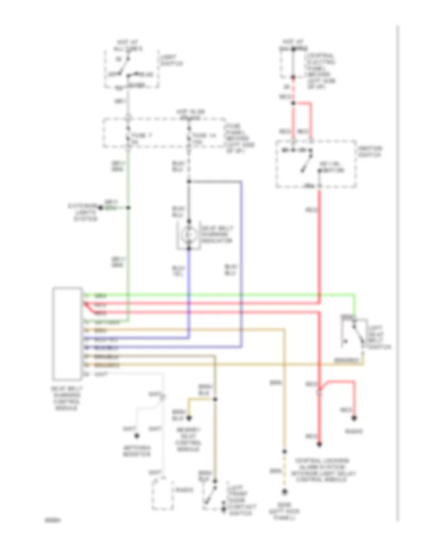
ANTI-THEFT
Anti-theft & Central Locking Wiring Diagram (1 of 2) for Audi 100 CS 1994
List of elements for Anti-theft & Central Locking Wiring Diagram (1 of 2) for Audi 100 CS 1994:
-
-
- (below right rear seat)
- (not used)
- (on trans- mission)
- 15a
- 86s
- A/t
- A/t only
- Acc
- Alarm
- All times
- Auxiliary relay panel 1 (behind left side of i/p)
- Back-up lights
- Battery
- Central electric panel (left of steering column)
- Central locking/ alarm system/ interior light delay control module
- Circuit breaker 12a
- Door lock switch
- Driver door handle alarm switch
- Emergency flasher
- Engine control module
- Footwell lights
- Front interior light
- Function switch
- Fuse 15a
- Fuse panel (behind left side of i/p)
- G131 (intake manifold)
- G202 (left i/p)
- G404 (near left
- Hazard/ turn lights
- Hood
- Horn
- Hot at
- Hot in run
- Ignition switch
- Key switch
- Multi-
- Nca
- Off
- Only
- Or acc
- Park/ neutral position relay
- Passenger door handle alarm switch
- Power window control module
- Power window control unit
- Radio
- Red
- S1/50z
- S4/b
- S4/p/n
- S4/rf
- S6/50a
- Seat belt warning control module
- Shift lock control module
- Start
- Starter
- Switch
- Taillight)
- Trunk light
- Trunk light switch
- Trunk lock alarm switch
Anti-theft & Central Locking Wiring Diagram (2 of 2) for Audi 100 CS 1994
List of elements for Anti-theft & Central Locking Wiring Diagram (2 of 2) for Audi 100 CS 1994:
-
-
- Left central locking system sensor
- Left front door contact switch
- Left rear door contact switch
- Memory program switch
- Memory seat control module
- Nca
- Power window control module
- Right central locking system sensor
- Right front door contact switch
- Right rear door contact switch
- Sunroof motor
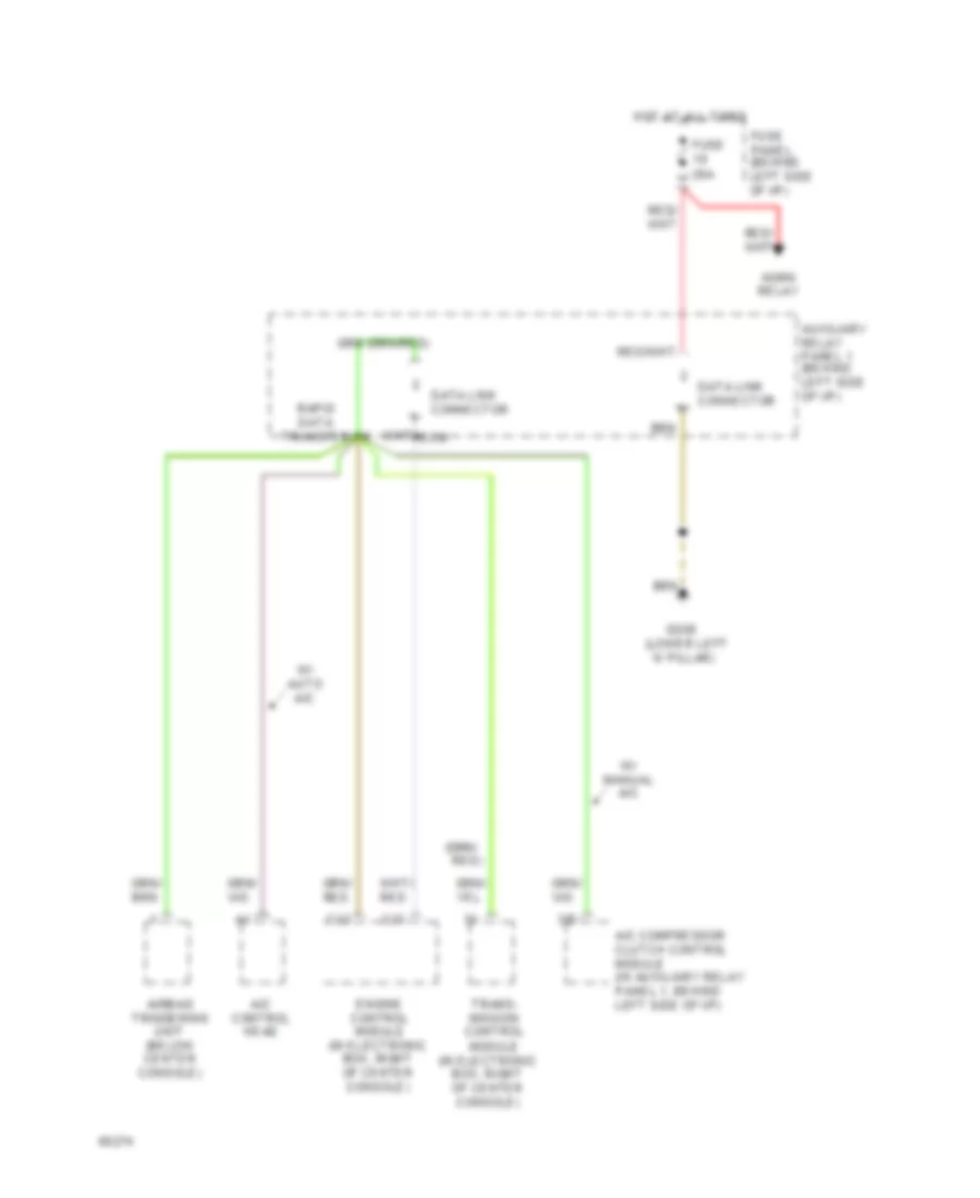
COMPUTER DATA LINES
Data Link Connector Wiring Diagram for Audi 100 CS 1994
List of elements for Data Link Connector Wiring Diagram for Audi 100 CS 1994:
- 'a' pillar)
- (in electronic box, right of center console)
- (lower left
- 3/d
- A/c compressor clutch control module (in auxiliary relay panel 1, behind left side of i/p)
- A/c control head
- Airbag triggering unit (below center console)
- Auxiliary relay panel 1 (behind left side of i/p)
- C12
- C13
- Data link connector
- Ecm
- Engine control module (in electronic box, right of center console)
- Fuse 25a
- Fuse panel (behind left side of i/p)
- G200
- Horn relay
- Hot at all times
- Rapid data transfer
- Red)
- Trans- mission control module
- W/ auto a/c
- W/ manual a/c
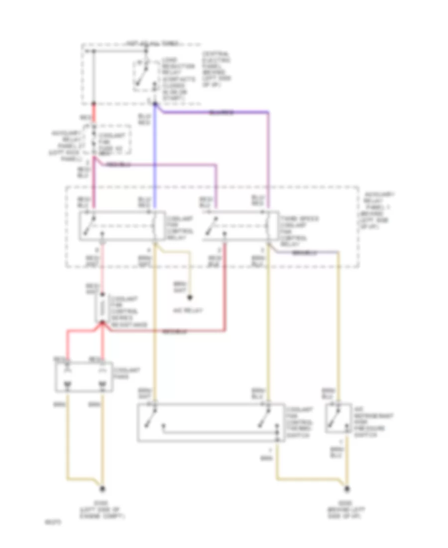
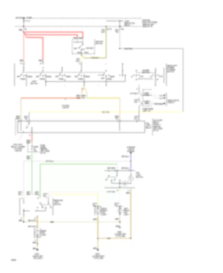
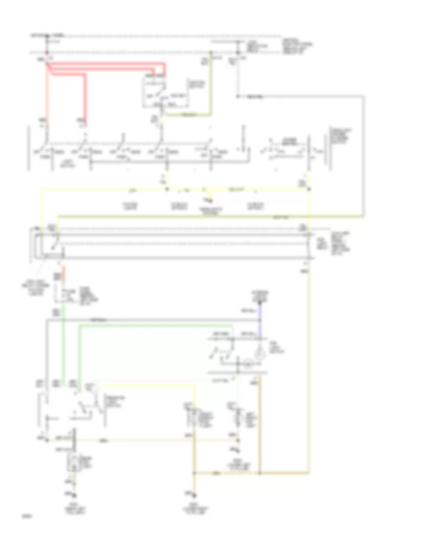
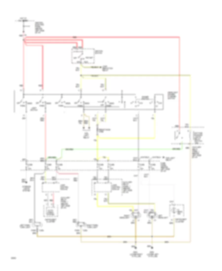
COOLING FAN
Cooling Fan Wiring Diagram for Audi 100 CS 1994
List of elements for Cooling Fan Wiring Diagram for Audi 100 CS 1994:
- (behind left side of i/p)
- (left kick
- (left side of engine compt)
- A/c refrigerant high pressure switch
- A/c relay
- Auxiliary
- Auxiliary relay panel 2
- Central electric panel (behind left side of i/p)
- Coolant fan fuse 42 60a
- Coolant fan control relay
- Coolant fan control series resistance
- Coolant fan control thermo- switch
- Coolant fans
- G100
- G202
- Hot at all times
- Load reduction relay (contacts closed in on or start)
- Panel 1
- Panel)
- Red
- Relay
- Third speed coolant fan control relay
CRUISE CONTROL
Cruise Control Wiring Diagram for Audi 100 CS 1994
List of elements for Cruise Control Wiring Diagram for Audi 100 CS 1994:
-
- A/c control head
- A/t
- A/t only
- Brake light switch
- Brake lights -or- rear lamp control module
- Brake vacuum vent valve
- Cluster
- Clutch vacuum vent valve
- Control module
- Cruise control module
- Cruise control switch
- Cruise control vacuum pump
- Electronic differential lock
- Engine control module
- Fuse 10a
- Fuse 15a
- Fuse 5a
- Fuse panel (behind left side of i/p)
- G900 (lower left "a" pillar)
- Hot at all times
- Hot in on or acc
- Instrument
- Jumper
- M/t
- M/t only
- Nca
- Outside air temp. display
- Servotronic control unit
- Shift lock control module
- Speedo- meter
- Transmission
- Vehicle speed output
- W/ motors over 150 bhp
- Wire connector (near cruise control module)
DEFOGGERS
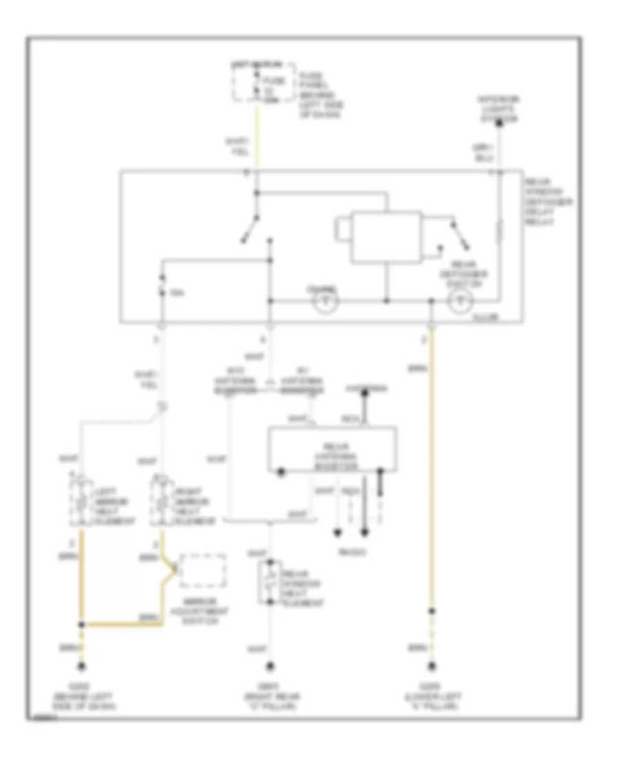
Defogger Wiring Diagram for Audi 100 CS 1994
List of elements for Defogger Wiring Diagram for Audi 100 CS 1994:
- 10a
- Antenna
- Fuse 30a
- Fuse panel (behind left side of dash)
- G200 (lower left "a" pillar)
- G202 (behind left side of dash)
- G905 (right rear "c" pillar)
- Hot in run
- Illum
- Interior lights system
- Left mirror heat element
- Mirror adjustment switch
- Nca
- On ind
- Radio
- Rear antenna booster
- Rear defogger switch
- Rear window defogger delay relay
- Rear window heat element
- Right mirror heat element
- W/ antenna booster
- W/o antenna booster
ELECTRONIC POWER STEERING
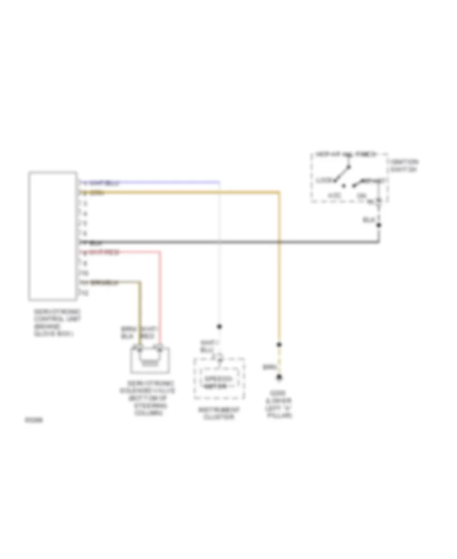
Electronic Power Steering Wiring Diagram for Audi 100 CS 1994
List of elements for Electronic Power Steering Wiring Diagram for Audi 100 CS 1994:
- (bottom of
- (lower left "a" pillar)
- Acc
- Cluster
- G200
- Hot at all times
- Ignition switch
- Instrument
- Lock
- Servotronic
- Servotronic control unit (behind glove box)
- Solenoid valve
- Speedo- meter
- Start
- Steering column)
ENGINE PERFORMANCE
2.8L
2.8L, Wiring Diagram (100 2.8L Wiring Diagram 1 Of 2) for Audi 100 CS 1994
List of elements for 2.8L, Wiring Diagram (100 2.8L Wiring Diagram 1 Of 2) for Audi 100 CS 1994:
- (in eng compt)
- (not used)
- (on intake manifold)
- 12a
- 15a
- 25a
- A10
- A11
- A12
- B10
- B11
- B12
- B13
- B14
- B15
- B16
- B17
- B18
- B19
- B20
- Central electrical unit
- Central locking/ alarm system/ interior light delay control module
- Closed throttle position switch/ throttle position sensor
- Computer display unit
- Egr temperature sensor
- Engine control module
- Fuse
- Fuse panel
- Hot at all times
- Hot in run or start
- Hot in start or run
- Ignition coil assembly
- Ignition coil circuit breaker
- In eng compt
- Instrument cluster
- Instrument clusters system (tach)
- Knock sensor #1
- Knock sensor #2
- Mal- function indicator "check engine"
- Mass air flow sensor
- Mass air flow sensor circuit breaker
- Multi- function switch
- Nca
- Power output stage
- Red
- Shift lock control module
- Spark plugs #1 & #6
- Spark plugs #2 & #4
- Spark plugs #3 & #5
- Transmission control module
2.8L, Wiring Diagram (100 2.8L Wiring Diagram 2 Of 2) for Audi 100 CS 1994
List of elements for 2.8L, Wiring Diagram (100 2.8L Wiring Diagram 2 Of 2) for Audi 100 CS 1994:
- (calif only)
- (in eng compt)
- (in rear wiring harness)
- 12a
- 15a
- 60a
- Air condi- tioning system
- Air control valve
- Air pump motor (calif only)
- Air pump relay (calif only)
- Battery(30)
- C1
- C10
- C11
- C12
- C13
- C14
- C15
- C16
- Central electrical panel
- Circuit breaker #72
- Circuit breaker #73
- Circuit breaker #87
- Crank- shaft position sensor
- D10
- D11
- D12
- D13
- D14
- D15
- D16
- Data link connector
- Eap frequency valve
- Egr frequency valve
- Engine control module
- Engine coolant temperature sensor
- Engine speed sensor
- Fuel injectors
- Fuel pump
- Fuel pump relay
- Fuse 15a
- Fuse panel
- Hall generator
- Iac valve
- Ign(15)
- Intake manifold change- over valve
- Nca
- O2 sensor #1
- O2 sensor #2
- O2 sensor heater
- Red
EXTERIOR LIGHTS
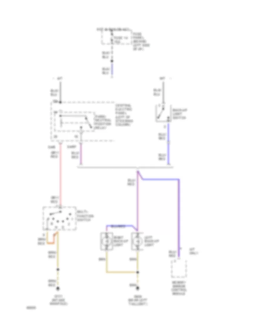
Back-up Lamps Wiring Diagram for Audi 100 CS 1994
List of elements for Back-up Lamps Wiring Diagram for Audi 100 CS 1994:
- 15a
- A/t
- A/t only
- Back-up light switch
- Central electric panel (left of steering column)
- Function switch
- Fuse 14 15a
- Fuse panel (behind left side of i/p)
- G131 (intake manifold)
- G404 (near left taillight)
- Hot in run or acc
- Left back-up light
- M/t
- Memory mirror control module
- Multi-
- Park/ neutral position relay
- Right back-up light
- S4/b
- S4/rf
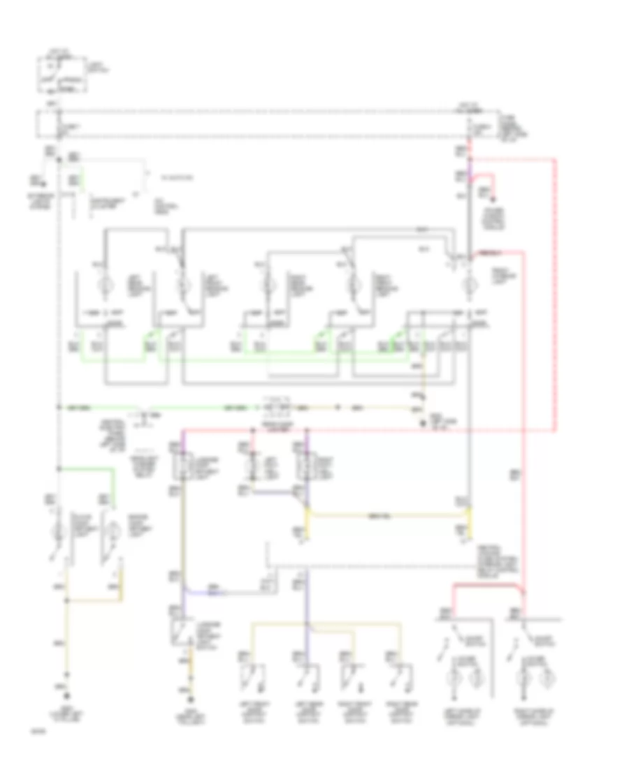
Park, Stop, Tail & Turn Lamps Wiring Diagram for Audi 100 CS 1994
List of elements for Park, Stop, Tail & Turn Lamps Wiring Diagram for Audi 100 CS 1994:
-
- A/t only
- Abs control module
- Anti-theft system
- Auto- check system
- Auxiliary relay panel 1 (behind left side of i/p)
- Brake light switch
- Brake vacuum vent valve
- Central electric panel (behind left side of i/p)
- Cluster
- Emergency flasher relay
- Emergency flasher switch
- Fuse 10a
- Fuse 15a
- Fuse 25a
- Fuse 5a
- Fuse panel (behind left side of i/p)
- G200 (lower left "a" pillar)
- G202 (behind left side of i/p)
- G203 (lower left "a" pillar)
- G203 (lower right "a" pillar)
- G404 (near left taillight)
- Head
- Headlights system
- High- mount stop
- Hot at all times
- Hot in run or acc
- Instrument
- Instrument cluster
- Interior
- Lamp control module
- Left front park/ turn light
- Left rear tail/stop/ turn lights
- Left turn ind.
- License plate
- Light
- Light switch
- Lights
- Lights system
- Off
- Park
- Red
- Right front park/ turn light
- Right rear tail/stop/ turn lights
- Right turn ind.
- Shift lock solenoid, shift lock control module
- Signal switch
- Solid state
- Stop
- Tail
- Transmission control module
- Turn
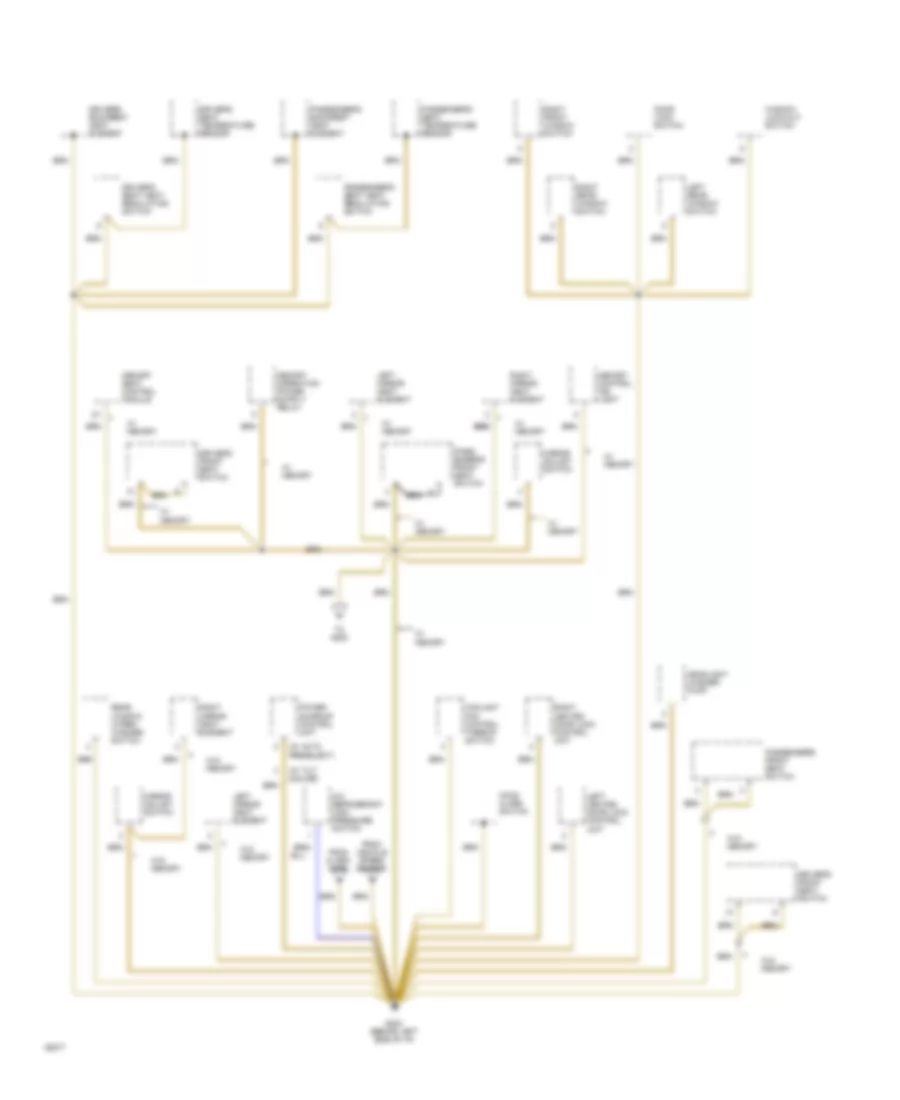
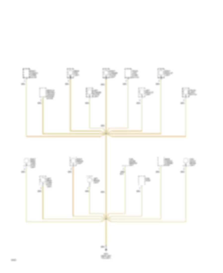
GROUND DISTRIBUTION
Ground Distribution Wiring Diagram (1 of 6) for Audi 100 CS 1994
List of elements for Ground Distribution Wiring Diagram (1 of 6) for Audi 100 CS 1994:
- Battery
- Closed throttle position switch
- Coolant fans
- Crankshaft position sensor
- D1 d1
- D16
- Egr temperature sensor
- Engine
- Engine control module
- Engine coolant temperature sensor
- Engine speed sensor
- G100 (left side of engine compt)
- G131 (intake manifold)
- G303 (below right rear seat)
- Generator
- Ground strap
- Hall generator
- Headlight washer pump
- Mass air flow sensor
- Multi- function switch
- Nca
- Power distribution system
- Power output stage
- Rear window shade control module
- Rear window shade switch
- Red
- Throttle position sensor
- Transmission control module
- W/ a/t
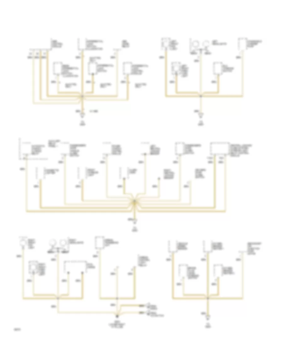
Ground Distribution Wiring Diagram (2 of 6) for Audi 100 CS 1994
List of elements for Ground Distribution Wiring Diagram (2 of 6) for Audi 100 CS 1994:
- (w/ auto preselect)
- (w/ tilt & slide)
- A/c refrigerant high pressure switch
- Coolant fan control thermo- switch
- Door lock switch
- Driver's backrest heat element
- Driver's front seat switch
- Driver's seat heat regulating switch
- Driver's seat temperature sensor
- From alarm horn
- From vehicle speed sensor
- G202 (behind left side of i/p)
- Headlight washer pump
- Hood alarm switch
- Left heated door lock control unit
- Left mirror heat element
- Left rear window switch
- Memory control ind. light
- Memory seat control module
- Mirror adjust switch
- Pass- enger's front seat switch
- Passenger's backrest heat element
- Passenger's front seat switch
- Passenger's seat heat regulating switch
- Passenger's seat temperature sensor
- Power sunroof control unit
- Rear window wiper/ washer switch
- Right front window switch
- Right heated door lock control unit
- Right mirror heat element
- Right rear window switch
- To g200
- W/ memory
- W/o memory
- Window lock-out switch
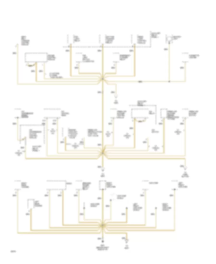
Ground Distribution Wiring Diagram (3 of 6) for Audi 100 CS 1994
List of elements for Ground Distribution Wiring Diagram (3 of 6) for Audi 100 CS 1994:
- Abs combi relay
- Abs control module
- Airbag control light relay
- Airbag triggering unit
- Alarm horn
- Automatic window closing relay
- Auxiliary relay panel 1
- Beam
- Brake fluid level warning switch
- Central locking/ alarm system/ interior light delay control module
- Cigarette lighter
- Differential lock control module
- Differential lock switch
- Differential lock switch illumination
- Driver's door alarm switch
- Dual horns
- Elc warning switch
- From a/c switch
- From radio
- Front interior light
- G203 (lower right "a" pillar)
- Left central locking sensor
- Left front fog light
- Left front park/ turn light
- Left headlights
- Oxygen sensor heater 1
- Oxygen sensor heater 2
- Passenger's door alarm switch
- Passenger's door handle alarm switch
- Power window control module
- Quattro only
- Rear differential lock switch/ illumination
- Right central locking sensor
- Right front fog light
- Right front park/ turn light
- Right headlights
- Secondary air injection pump motor
- T16/3
- T6/3
- To g200
- To g202
- Vehicle speed sensor
- W/ abs
- Windshield washer pump
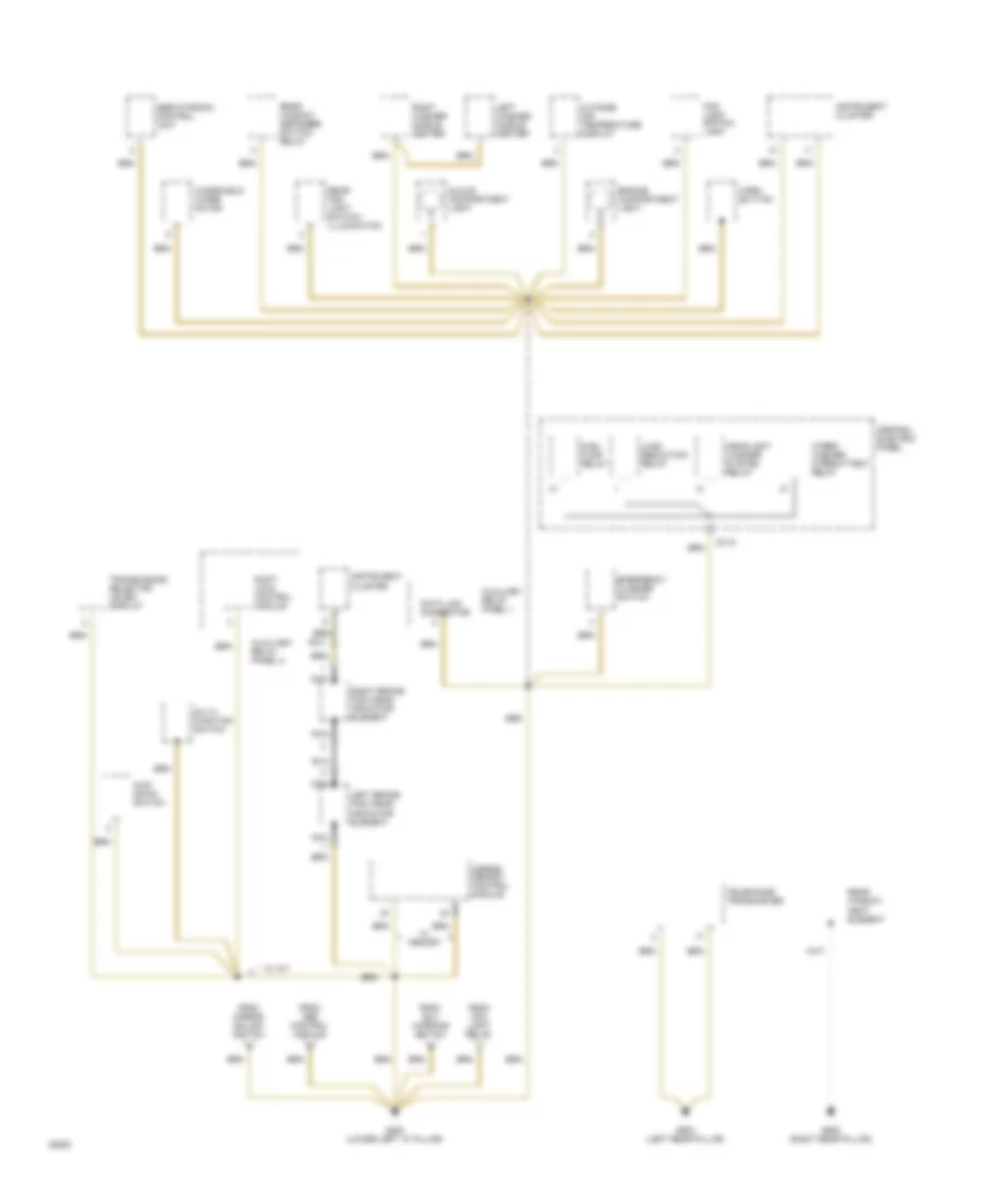
Ground Distribution Wiring Diagram (4 of 6) for Audi 100 CS 1994
List of elements for Ground Distribution Wiring Diagram (4 of 6) for Audi 100 CS 1994:
- A/c compressor clutch control module
- A/c compressor speed sensor
- A/c control head
- A/c relay
- A/c switch
- Amplifier
- Amplifier shield
- Ashtray light
- Auxiliary relay panel 1
- Cigarette lighter
- Cruise control module
- D14
- D15
- Daytime running lights relay
- Emergency flasher relay
- Engine coolant two-way vacuum valve
- Fog light relay
- Fog light switch/ illumination
- Fresh air blower control
- Fresh air blower series resistance w/ fuse
- Fresh air blower switch
- Fresh air recirculation flap two- way valve
- G201 (behind right side of i/p)
- Left front amplifier
- Left front amplifier shield
- Left rear woofer
- Module
- Radio
- Rear lamp control module
- Right front amplifier
- Right front amplifier shield
- Right rear woofer
- Seat belt warning control module
- Than 150 bph
- To g200
- To g203
- To horn button
- W/ auto a/c
- W/ manual a/c
- W/ more
- W/ motors
Ground Distribution Wiring Diagram (5 of 6) for Audi 100 CS 1994
List of elements for Ground Distribution Wiring Diagram (5 of 6) for Audi 100 CS 1994:
- Auxiliary relay panel 1
- Auxiliary relay panel 2
- Central electric panel
- Data link connector
- Emergency flasher switch
- Engine compartment light
- Fog light switch light
- From abs control module
- From elc warning switch
- From fog light relay
- From mirror adjust switch
- Fuel pump relay
- G200 (lower left "a" pillar)
- G904 (left rear pillar)
- G905 (right rear pillar)
- Glove compartment light
- Headlight washer system relay
- Horn button
- Instrument cluster
- Kick down switch
- Left brake pad wear indicator element
- Left washer nozzle heater
- Load reduction relay
- Memory
- Mirror memory control module
- Multi- function switch
- Nca
- Outside air temperature display
- Rear fog light switch/ illumination
- Rear window defogger switch/ relay
- Rear window heat element
- Right brake pad wear indicator element
- Right washer nozzle heater
- S1/31
- Servotronic control unit
- Shift lock control module
- Telephone transciever
- Transmission selector lever display
- W/ a/t
- Windshield wiper motor
- Wiper/ washer intermittent relay
Ground Distribution Wiring Diagram (6 of 6) for Audi 100 CS 1994
List of elements for Ground Distribution Wiring Diagram (6 of 6) for Audi 100 CS 1994:
- Decklid central locking system motor
- Fuel gauge sending unit
- Fuel pump
- G404 (near left taillight)
- High mount brake light
- Left back-up light
- Left brake light
- Left license plate light
- Left rear turn/ stop light
- Rear fog light
- Rear window washer pump
- Right back-up light
- Right brake light
- Right license plate light
- Right rear turn/ stop light
- Right window wiper motor
- Trunk light switch
- Trunk lock alarm switch
HEADLIGHTS
Fog Lamps Wiring Diagram, Canada for Audi 100 CS 1994
List of elements for Fog Lamps Wiring Diagram, Canada for Audi 100 CS 1994:
-
- fuse 2
- (behind left side of i/p)
- (lower left "a" pillar)
- (lower right "a" pillar)
- (near left taillight)
- 10a
- 10a
- 75x
- Acc
- Auxiliary relay panel 1 (behind left side of i/p)
- Central electric panel
- Dimmer switch
- Fog light relay
- Fog light relay jumper (w/o fog lights)
- Fog light switch
- Ftp
- Fuse 1
- Fuse 15a
- Fuse panel (behind left side of i/p)
- Fuse panel (left i/p)
- G200
- G203
- G404
- Head
- Headlight dimmer/ flasher switch
- Headlights circuit
- Hot at all times
- Ignition switch
- Interior lights system
- Left front fog light
- Light switch
- Load reduction relay
- Off
- Park
- Rear fog light
- Rear fog light switch
- Red
- Right front fog light
- Run
- S1/75
- Start
- W/o fog lights
Fog Lamps Wiring Diagram, USA for Audi 100 CS 1994
List of elements for Fog Lamps Wiring Diagram, USA for Audi 100 CS 1994:
-
- (behind left side of i/p)
- (lower left "a" pillar)
- (lower right "a" pillar)
- (near left taillight)
- 75x
- Acc
- Auxiliary relay panel 1 (behind left side of i/p)
- Central electric panel
- Dimmer switch
- Fog light relay
- Fog light relay jumper (w/o fog lights)
- Fog light switch
- Ftp
- Fuse 15a
- Fuse panel (behind left side of i/p)
- G200
- G203
- G404
- Head
- Headlight dimmer/ flasher switch
- Headlights system
- Hot at all times
- Ignition switch
- Interior lights system
- Left front fog light
- Light switch
- Load reduction relay
- Off
- Park
- Rear fog light
- Rear fog light switch
- Red
- Right front fog light
- Run
- S1/75
- Start
- W/ build option 1
- W/ build option 2
- W/o fog lights
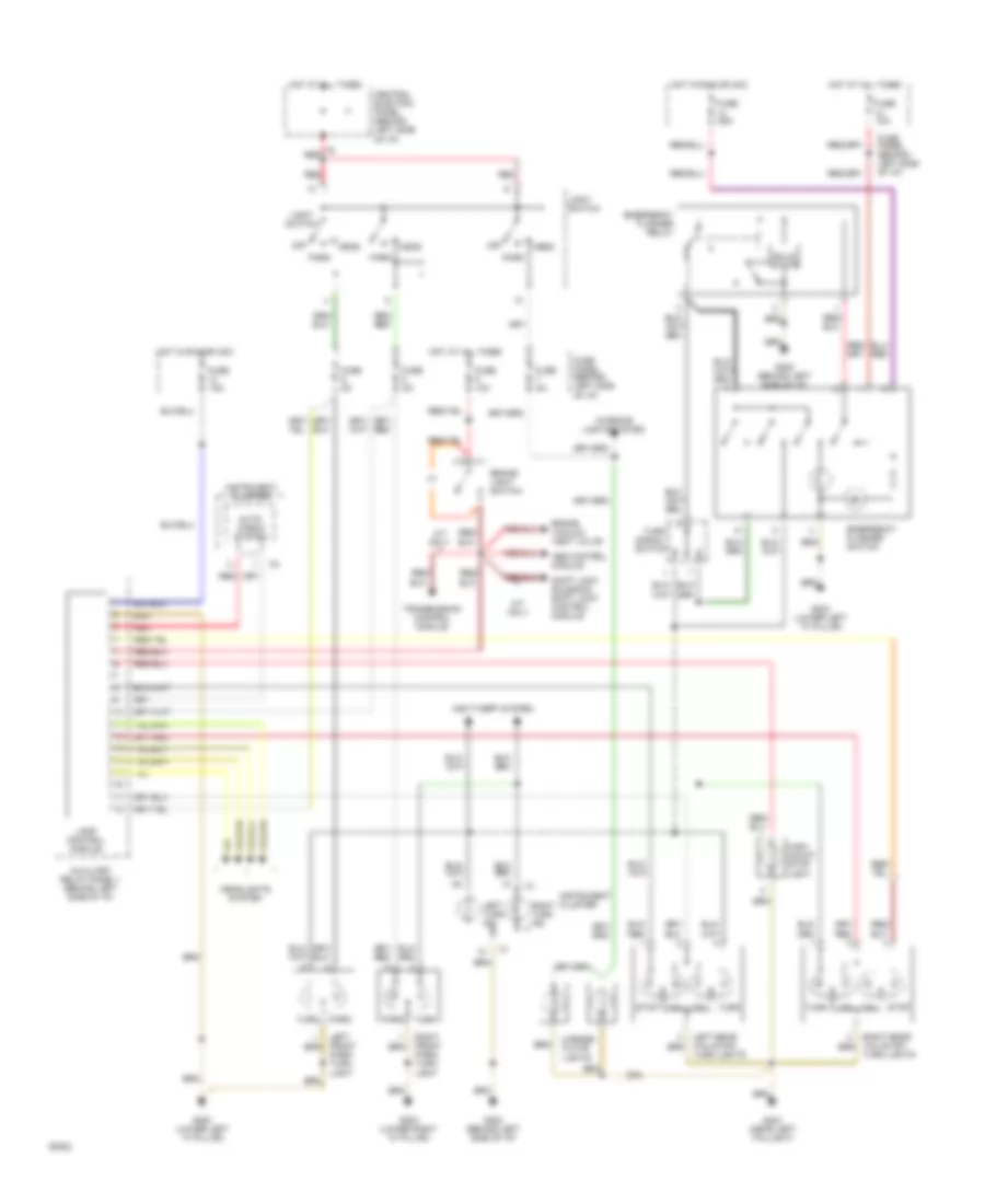
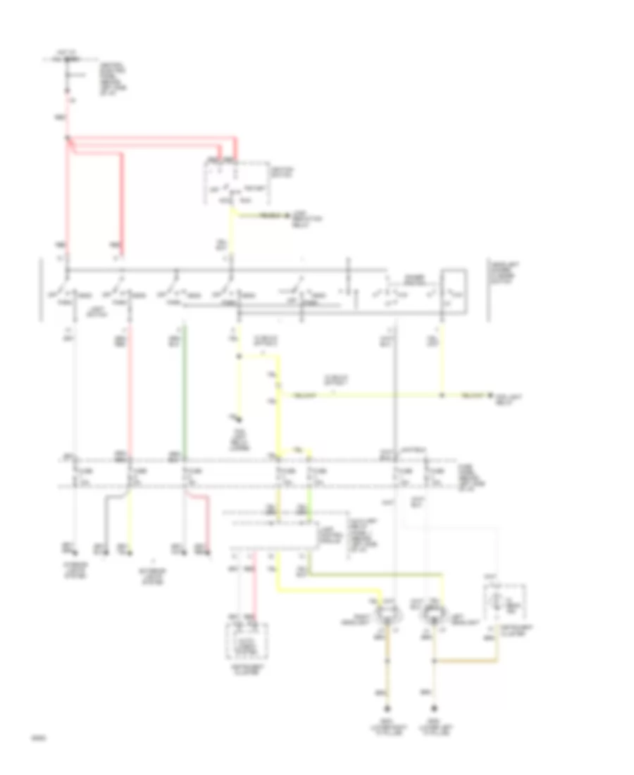
Headlamps Wiring Diagram, Canada for Audi 100 CS 1994
List of elements for Headlamps Wiring Diagram, Canada for Audi 100 CS 1994:
- (lower left "a" pillar)
- (lower right "a" pillar)
- Acc
- All times
- Auto- check system
- Auxiliary relay panel 1 (behind left side of i/p)
- Central electric panel (behind left side of i/p)
- Cluster
- Daytime running lights relay (switch -on)
- Dimmer switch
- Fog light relay
- Ftp
- Fuse 10a
- Fuse 5a
- Fuse panel (behind left side of i/p)
- G200
- G203
- Head
- Headlight dimmer/ flasher switch
- Hi beam ind.
- Hot at
- Ignition switch
- Instrument
- Instrument cluster
- Interior lights system
- Lamp control module
- Left headlight
- Left park/ turn light
- Light switch
- Load reduction relay
- Off
- Park
- Red
- Resistance wire
- Right headlight
- Right park/ turn light
- Run
- Start
- Turn
Headlamps Wiring Diagram, USA for Audi 100 CS 1994
List of elements for Headlamps Wiring Diagram, USA for Audi 100 CS 1994:
- (lower left "a" pillar)
- (lower right "a" pillar)
- Acc
- All times
- Auto- check system
- Auxiliary relay panel 1 (behind left side of i/p)
- Central electric panel (behind left side of i/p)
- Cluster
- Dimmer switch
- Exterior lights system
- Fog light relay
- Fog light relay jumper
- Ftp
- Fuse 10a
- Fuse 5a
- Fuse panel (behind left side of i/p)
- G200
- G203
- Head
- Headlight dimmer/ flasher switch
- Hi beam ind.
- Hot at
- Ignition switch
- Instrument
- Instrument cluster
- Interior lights system
- Lamp control module
- Left headlight
- Light switch
- Load reduction relay
- Off
- Park
- Red
- Right headlight
- Run
- Start
- W/ build option 1
- W/ build option 2
HORN
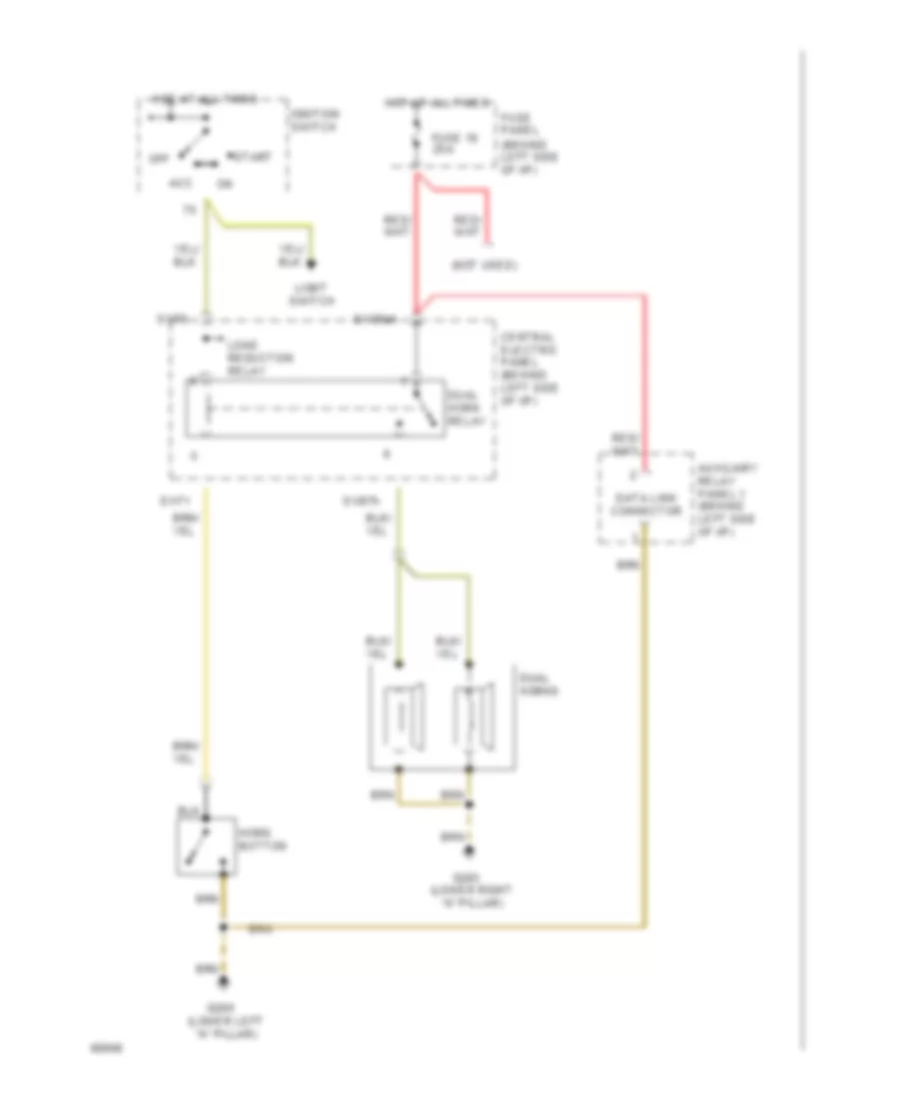
Horn Wiring Diagram for Audi 100 CS 1994
List of elements for Horn Wiring Diagram for Audi 100 CS 1994:
-
-
- (behind left side of i/p)
- (not used)
- Acc
- Auxiliary relay panel 1 (behind left side of i/p)
- Central electric panel (behind left side of i/p)
- Data link connector
- Dual horn relay
- Dual horns
- Fuse 19 25a
- Fuse panel
- G200 (lower left "a" pillar)
- G203 (lower right "a" pillar)
- Horn button
- Hot at all times
- Ignition switch
- Light switch
- Load reduction relay
- Off
- On
- S1/30ah
- S1/71
- S1/75
- S1/87h
- Start
INSTRUMENT CLUSTER
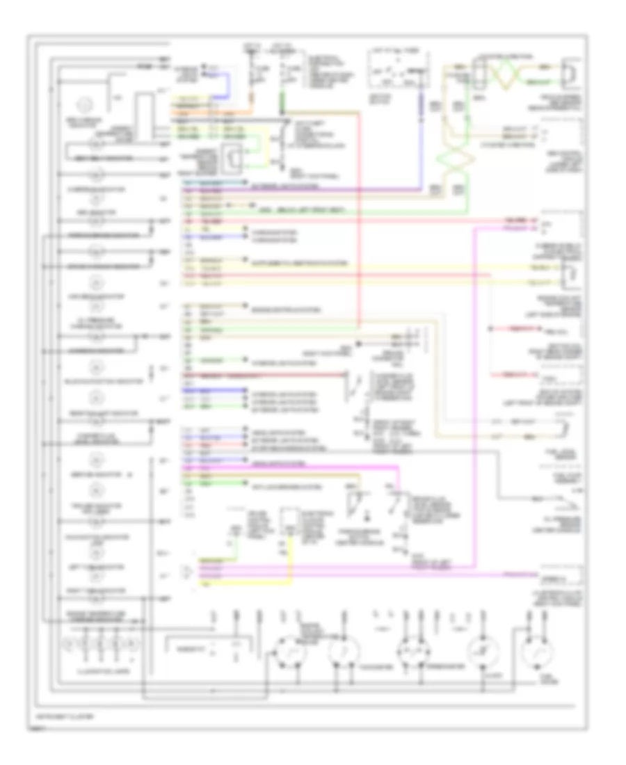
Instrument Cluster Wiring Diagram for Audi 100 CS 1994
List of elements for Instrument Cluster Wiring Diagram for Audi 100 CS 1994:
- (+)
- (-)
- (2.3l turbo)
- (2.3l)
- (at steering column)
- (below left front seat)
- (front of right front fender) g101
- (twisted pair)
- (twisted wire pair)
- 87a
- A10
- A11
- A12
- A13
- A14
- Abs control module (under left side of dash)
- Abs indicator
- Acc
- Ambient temperature gauge
- Ambient temperature sensor (behind front bumper)
- Anti-lock brakes system
- Anti-theft alarm connector #2 (partial)
- B10
- B11
- B12
- B13
- B14
- Brake fluid level sensor (top of brake master cylinder reservoir)
- Brake warning indicator
- Bulb malfunction indicator
- C10
- C11
- C12
- Charging indicator
- Clock
- Cruise control module (left kick panel)
- Electrical distribution unit (center of dash, under center console)
- Electronic climate control module (center of i/p)
- Engine controls system
- Engine coolant temperature gauge
- Engine coolant temperature sensor (left side of engine)
- Engine temperature warning indicator
- Exterior lights system
- Ez-k (di) system power amplifier (left front of engine compt)
- Fuel gauge
- Fuel level sensor
- Fuel pump assembly
- Fuse
- Fuse 15a
- G100 (front of left front fender)
- G203 (right kick panel)
- G300
- Ground connector rail
- Headlights system
- Hic
- High beam indicator
- Hot at all times
- Hot in run
- Ignition coil (right rear corner of engine compt)
- Ignition switch
- Illumination lamps
- Indicator
- Instrument cluster
- Interior lights system
- Left turn indicator
- Lh-jetronic 2.4 mfi control module (right kick panel)
- Lvl
- Malfunction indicator lamp
- Off
- Oil pressure
- Oil pressure sensor (center console)
- Overdrive indicator
- Overdrive relay (in electrical distribution unit)
- Parking brake indicator
- Parking brake switch (center console)
- Prim coil
- Rear fog lamp indicator
- Red
- Rheostat
- Right turn indicator
- Run
- Seal
- Seat belt indicator
- Service indicator
- Spd in
- Speed in
- Speedometer
- Srs warning
- Start
- Starting/charging system
- Tach
- Tachometer
- Trailer indicator (not used)
- Vehicle speed/ abs sensor (rear differential)
- Warning indicator
- Warning system
- Washer fluid level indicator
- Washer fluid level sensor (left front of engine compt in reservoir)
INTERIOR LIGHTS
Courtesy Lamps Wiring Diagram (1 of 2) for Audi 100 CS 1994
List of elements for Courtesy Lamps Wiring Diagram (1 of 2) for Audi 100 CS 1994:
- (left side
- (optional)
- 58a
- A/c control head
- C1/17
- Central electric panel (behind left side of i/p)
- Central locking/ alarm system/ interior light delay control module
- Cover switch
- Door
- Engine comp- artment light
- Exterior
- Front interior light
- Fuse 7 5a
- Fuse 8 15a
- Fuse panel (behind left side of i/p)
- G200 (lower left "a" pillar)
- G202
- G404 (near left taillight)
- Glove comp- artment light
- Head
- Headlight washer system relay
- Hot at all times
- Instrument cluster
- Left foot- well light
- Left front door contact switch
- Left front reading light
- Left make-up mirror light
- Left rear door contact switch
- Left rear reading light
- Light switch
- Lights system
- Luggage comp- artment light
- Luggage comp- artment light switch
- Of i/p)
- Off
- On/off switch
- Park
- Power window control module
- Rear cigar lighter
- Right foot- well light
- Right front door contact switch
- Right front reading light
- Right make-up mirror light
- Right rear door contact switch
- Right rear reading light
- W/ auto a/c
Courtesy Lamps Wiring Diagram (2 of 2) for Audi 100 CS 1994
List of elements for Courtesy Lamps Wiring Diagram (2 of 2) for Audi 100 CS 1994:
- 15a
- 2-w/o memory 3-w/ memory
- Central electric panel (behind left side of i/p)
- Driver seat heat regulating switch
- Emergency flasher switch
- Fuse 13 25a
- Fuse 14 15a
- Fuse 15 5a
- Fuse panel (behind left side of i/p)
- G200 (lower left "a" pillar)
- G202 (behind left side of i/p)
- G303 (below right rear seat)
- Hot in run or acc
- Mirror adjustment switch
- Passenger seat heat regulating switch
- Rear
- Rear defoggers system
- Seat temperature sensors
- Sunshade
- Switch
- W/o memory only
- Window
Instrument Illumination Wiring Diagram for Audi 100 CS 1994
List of elements for Instrument Illumination Wiring Diagram for Audi 100 CS 1994:
- A/c control head
- A/t console light
- Ashtray light
- Auto a/c
- Auto check system
- Auxiliary relay panel 1 (behind left side of i/p)
- C1-10
- C1-17
- C1-22
- Cigar lighter light
- Differ- ential lock switch
- Dim input
- Dimmer switch
- Exterior
- Fresh air blower switch
- Front fog light switch
- Fuse 7 5a
- Fuse 8 15a
- Fuse panel (behind left side of i/p)
- G200 (lower left "a" pillar)
- G203 (lower right "a" pillar)
- Generator
- Head
- Hot at all times
- Illum. lights
- Instrument cluster
- Light switch
- Lights system
- Manual a/c
- Off
- Optional
- Outside air temperature display
- Park
- Protection diode
- Quattro w/ abs
- Radio
- Rear fog light switch
- Rear window defogger switch
- Selector lever light relay
- Transmission selector lever display
- W/ a/t
MEMORY SYSTEMS
Memory Seat & Mirrors Wiring Diagram (1 of 2) for Audi 100 CS 1994
List of elements for Memory Seat & Mirrors Wiring Diagram (1 of 2) for Audi 100 CS 1994:
-
- front height
- (central locking/ alarm system/ interior light delay control module)
- (left front door contact switch)
- Anti-theft system
- Auxiliary relay panel 1 (behind left side of i/p)
- Back- rest
- Circuit breaker 44 30a
- Driver seat backrest adjusting motor/position sensor
- Driver seat fore/ aft adjusting motor/position sensor
- Driver seat front height adjusting motor/position sensor
- Driver seat rear height adjusting motor/position sensor
- Driver seat switch
- Fore/ aft
- Hot at all times
- Memory program switch
- Memory seat control module
- Rear height
- Red
- Warnings system
Memory Seat & Mirrors Wiring Diagram (2 of 2) for Audi 100 CS 1994
List of elements for Memory Seat & Mirrors Wiring Diagram (2 of 2) for Audi 100 CS 1994:
-
- (behind left side of i/p)
- Back-up lights (a/t-multi- function switch) (m/t-back-up light switch)
- Defoggers system
- Element
- Fuse 15 5a
- Fuse 8 15a
- Fuse panel
- G200 (lower left "a" pillar)
- G202 (behind left side of i/p)
- Heat
- Heat element
- Hot at all times
- Hot in run or acc
- Left mirror motor
- Memory mirror control module
- Mirror adjustment switch
- Mirror position
- Mirror select
- Red
- Red
- Right mirror motor
POWER DISTRIBUTION
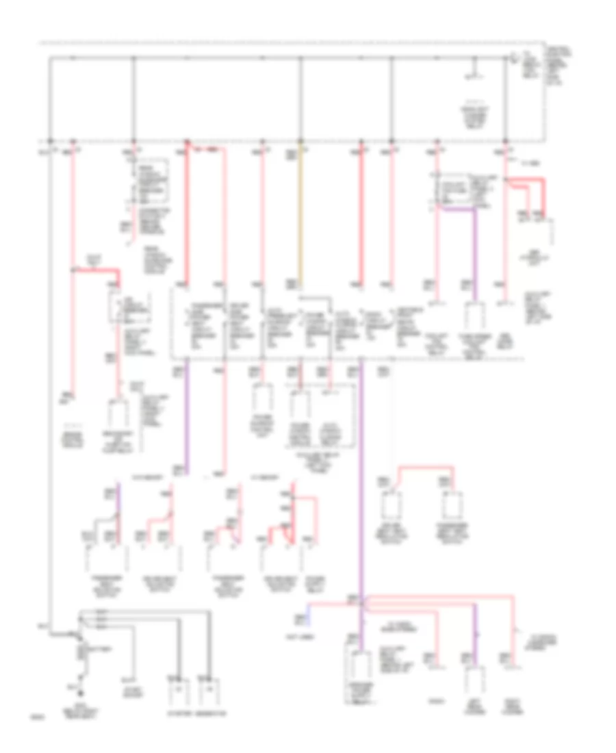
Power Distribution Wiring Diagram (1 of 4) for Audi 100 CS 1994
List of elements for Power Distribution Wiring Diagram (1 of 4) for Audi 100 CS 1994:
- (not used)
- Abs combi relay
- Abs hydraulic unit
- Air circuit breaker 60a
- Auto preselect sunroof circuit breaker 20a
- Auto window
- Auto window closing circuit breaker 30a
- Auxiliary relay
- Auxiliary relay panel 1 (behind left side of i/p)
- Auxiliary relay panel 2 (left kick panel)
- Auxiliary relay panel 3 (right kick panel)
- B20
- Battery
- Bose stereo
- Calif. only
- Central electric panel (behind left side
- Closing relay
- Connector station 3 (behind center console)
- Control module
- Control unit
- Coolant fan control
- Coolant fan fuse 60a
- Driver seat adjusting switch
- Driver seat heat regulating switch
- Driver side power
- Engine control module
- G303 (below right rear seat)
- Generator
- Headlight washer system relay
- Heatable front
- Left rear woofer
- Of i/p)
- Panel 2 (left kick
- Panel)
- Passenger seat adjusting switch
- Passenger seat heat regulating switch
- Passenger side power
- Power sunroof
- Power window
- Power window circuit breaker 30a
- Pump relay
- Radio
- Radio circuit breaker 12a
- Rear window sunshade circuit breaker 12a
- Rear window sunshade control module
- Red
- Relay
- Right rear woofer
- Seat circuit breaker 30a
- Seats circuit breaker 30a
- Secondary air injection
- Start socket
- Starter
- Stereo
- Third speed coolant fan control relay
- To load reduc- tion relay
- W/ abs
- W/ audio/
- W/ gamma 8-speaker
- W/ memory
- W/o memory
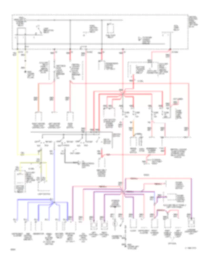
Power Distribution Wiring Diagram (2 of 4) for Audi 100 CS 1994
List of elements for Power Distribution Wiring Diagram (2 of 4) for Audi 100 CS 1994:
- (a/t only)
- (left kick panel)
- (not used)
- (w/ auxiliary heating)
- 10a
- 19a
- 50b
- 86s
- A/c control head (w/ auto a/c)
- Abs control module (abs only)
- Acc
- Auxiliary
- Auxiliary relay panel 1 (behind left side of i/p)
- Auxiliary relay panel 2
- Battery cut-out relay
- Brake light switch
- C 1995 vftc
- C13
- Capa- citor
- Central electric panel (behind left side of i/p)
- Central locking system motor circuit breaker 12a
- Central locking/ alarm system/ interior light delay control module
- Cigarette lighter
- Clock
- Control module
- Data link connector
- Daytime running lights relay
- Door lock switch
- Dual horn relay
- Emergency flasher switch
- Fresh air blower relay
- From headlight washer system relay
- Front interior light
- Fuel pump relay
- Fuse 10a
- Fuse 15a
- Fuse 25a
- Fuse panel (left side of i/p)
- G200 (lower left "a" pillar)
- Generator
- Heatable door locks circuit breaker 12a
- Ignition switch
- Instrument cluster
- Interior lights system (rheostat)
- Key-in ignition switch
- Left footwell light
- Left heated door lock control unit
- Left make-up mirror light
- Left side
- Light switch
- Light switch & headlight dimmer/ flasher switch
- Load reduction relay
- Luggage compartment light
- Nca
- Of i/p)
- Off
- Optional
- Panel 1 (behind
- Park/ neutral position relay
- Power window control module
- Power window lock-out switch
- Radio
- Red
- Relay
- Right footwell light
- Right heated door lock control unit
- Right make-up mirror light
- Run
- S1/30ah
- S1/50z
- S1/75
- Seat belt warning control module
- Selector lever light relay (a/t only)
- Start
- T12/2
- T6/1
- T6/2
- To power window control module
- To servotronic control unit
- Transmission
- W/ drl
- W/ gamma anti-theft radio
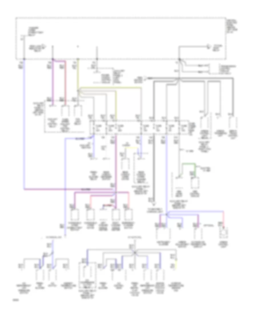
Power Distribution Wiring Diagram (3 of 4) for Audi 100 CS 1994
List of elements for Power Distribution Wiring Diagram (3 of 4) for Audi 100 CS 1994:
- (right kick panel)
- 11a
- 12a
- 13a
- 14a
- 15a
- 18a
- 21a
- 75a
- 75x
- A/c compressor clutch
- A/c control head
- A/c refrigerant low pressure switch
- A/c switch
- Abs combi relay
- Abs control module
- Airbag control light
- Airbag control light relay
- Airbag triggering unit
- Ambient temperature switch
- Auxiliary
- Auxiliary relay panel 1 (behind left side of i/p)
- Auxiliary relay panel 2 (left kick panel)
- C16
- Central electric panel (behind left side
- Coolant fan control
- Emergency flasher switch
- Engine coolant two-way
- Fan
- Flap two-way valve
- Fog light relay
- Fresh air blower
- Fresh air blower relay
- Fresh air/ recirc.
- From ignition switch
- From load b reduction relay
- Fuse 15a
- Fuse 25a
- Fuse 30a
- Fuse 5a
- Fuse panel (left side of i/p)
- Instrument cluster
- Interior temperature sensor
- Intermittent
- Left side
- Left washer nozzle heater
- Mirror adjustment switch
- Module
- Of i/p)
- Optional
- Outside air temperature display
- Panel 1 (behind
- Panel 3
- Power window control
- Pump relay
- Quattro w/ abs
- Rear window defogger switch
- Rear window wiper motor
- Rear window wiper/ washer relay
- Relay
- Right washer nozzle heater
- Servo- tronic control unit
- Third speed coolant fan control relay
- To fuel
- To seatbelt warning light
- Transmission control module (a/t only)
- Vacuum valve
- W/ abs
- W/ auto a/c
- W/ auxiliary heating
- W/ manual a/c
- Wagon
- Washer/
- Windshield wiper intermittent switch
- Windshield wiper motor
- Wiper
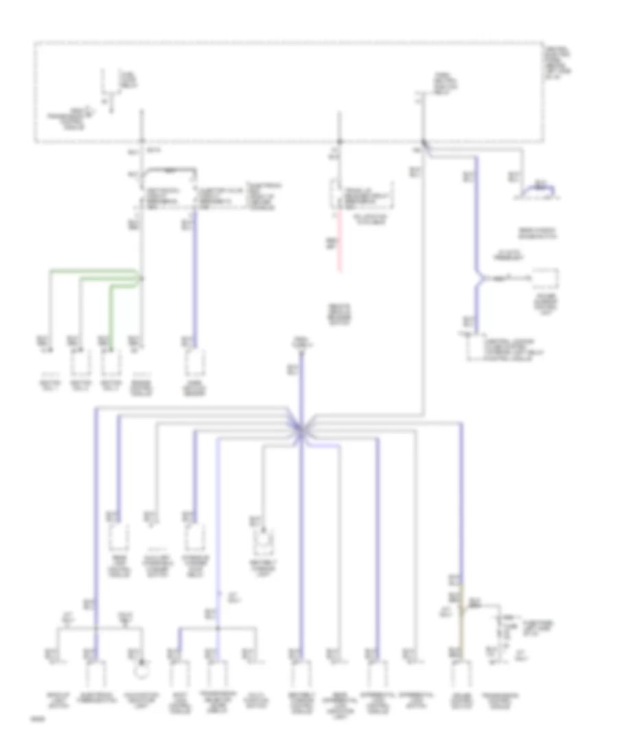
Power Distribution Wiring Diagram (4 of 4) for Audi 100 CS 1994
List of elements for Power Distribution Wiring Diagram (4 of 4) for Audi 100 CS 1994:
- 15a
- 20a
- A/t only
- Auxiliary windshield washer switch
- Available
- Back-up light switch
- Calif. only
- Central electric panel (behind left side
- Central locking/ alarm system/ interior light delay control module
- Cruise control switch
- Differential lock control module
- Differential lock switch
- Electronic box (right of center console)
- Electronic thermoswitch
- Engine control module
- From
- From d transmission control module
- Fuel pump relay
- Fuse 14
- Fuse 5a
- Fuse panel (left side of i/p)
- Ignition coil 1
- Ignition coil 2
- Ignition coil 3
- Ignition coil circuit breaker 64 15a
- Injector valve circuit breaker 72 12a
- Intensive washer pump relay
- M/t only
- Malfunction indicator light
- Mass air flow sensor
- Multi- function switch
- Nca
- Neutral
- No location
- Of i/p)
- Park/
- Position
- Power sunroof control unit
- Rear differential lock indicator light
- Rear lamp control module
- Rear window shade switch
- Relay
- Remote decklid release switch
- S3/15
- Seatbelt
- Seatbelt warning control module
- Shift lock control module
- T12/1
- Transmission control module
- Transmission selector lever display
- Trunk lid release circuit breaker 64 12a
- W/ auto preselect
- Warning light
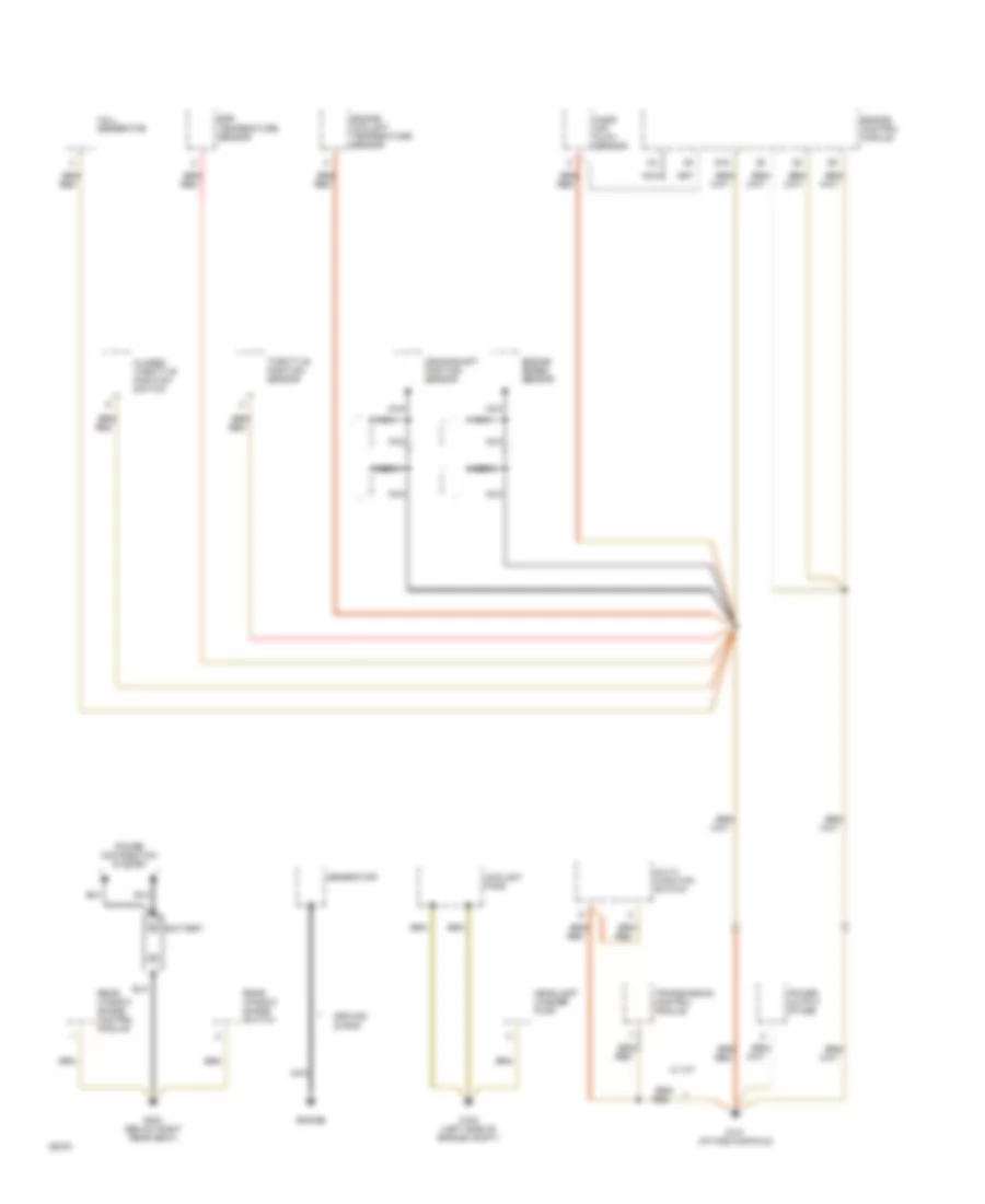
POWER DOOR LOCKS
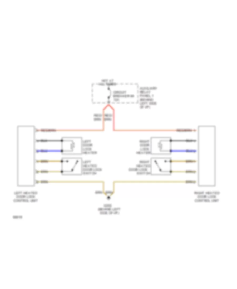
Heated Door Locks Wiring Diagram for Audi 100 CS 1994
List of elements for Heated Door Locks Wiring Diagram for Audi 100 CS 1994:
- All times
- Auxiliary relay panel 1 (behind left side of i/p)
- Circuit breaker 86 12a
- Door lock
- G202 (behind left side of i/p)
- Heated
- Heater
- Hot at
- Left door lock heater
- Left heated door lock control unit
- Left heated door lock switch
- Right
- Right door lock
- Right heated door lock control unit
- Switch
POWER MIRRORS
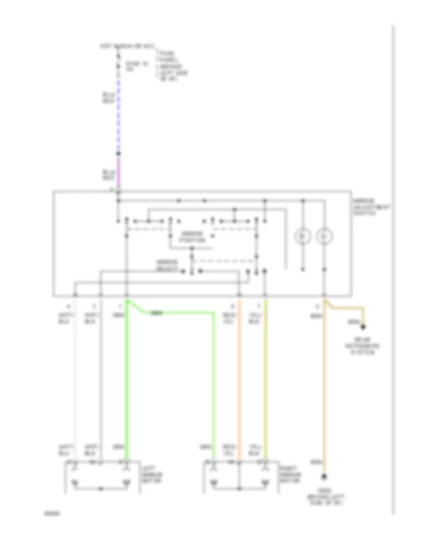
Power Mirrors Wiring Diagram for Audi 100 CS 1994
List of elements for Power Mirrors Wiring Diagram for Audi 100 CS 1994:
- (behind left side of i/p)
- Fuse 15 5a
- Fuse panel
- G202 (behind left side of i/p)
- Hot in run or acc
- Left mirror motor
- Mirror adjustment switch
- Mirror position
- Mirror select
- Rear defoggers system
- Right mirror motor
POWER SEATS
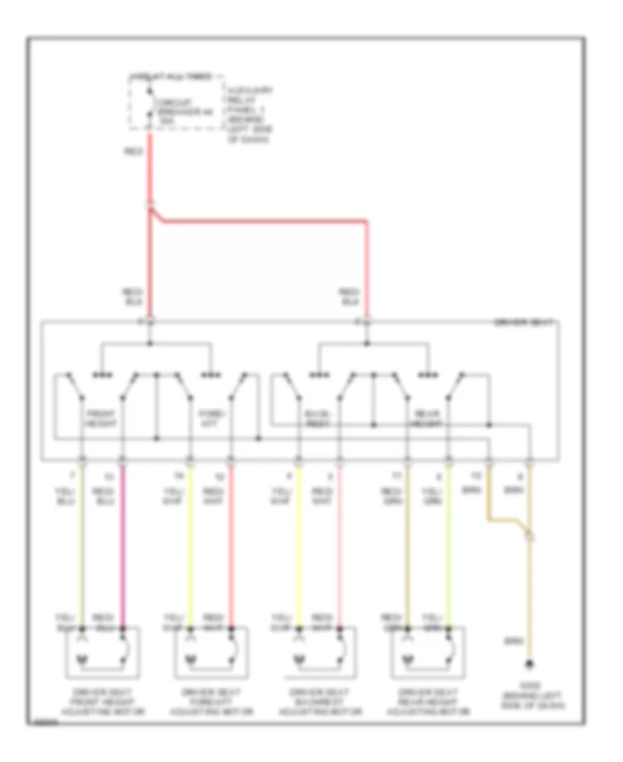
Driver Seat Wiring Diagram, without Memory for Audi 100 CS 1994
List of elements for Driver Seat Wiring Diagram, without Memory for Audi 100 CS 1994:
- Auxiliary relay panel 1 (behind left side of dash)
- Back- rest
- Circuit breaker 44 30a
- Driver seat
- Driver seat backrest adjusting motor
- Driver seat fore/aft adjusting motor
- Driver seat front height adjusting motor
- Driver seat rear height adjusting motor
- Fore/ aft
- Front height
- G202 (behind left side of dash)
- Hot at all times
- Rear height
- Red
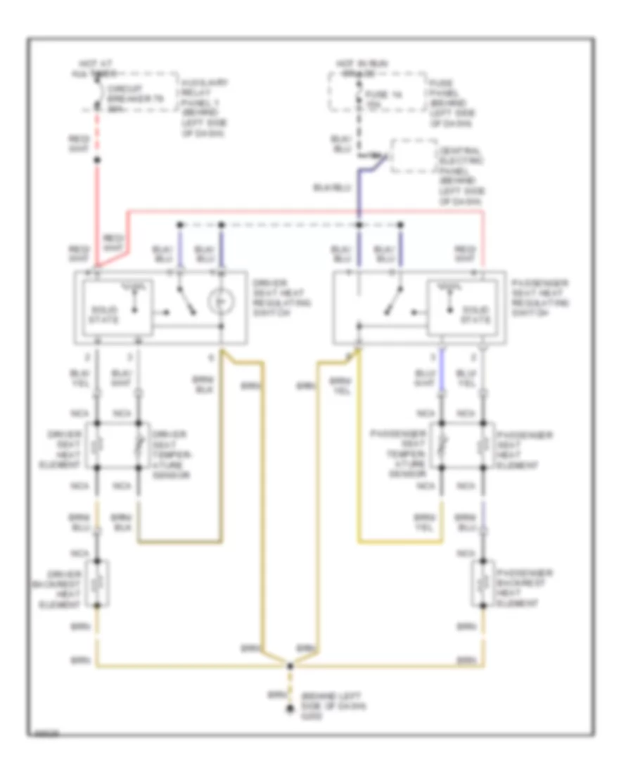
Heated Seats Wiring Diagram for Audi 100 CS 1994
List of elements for Heated Seats Wiring Diagram for Audi 100 CS 1994:
- (behind left side of dash) g202
- 15a
- All times
- Auxiliary relay panel 1 (behind left side of dash)
- Central electric panel (behind left side of dash)
- Circuit breaker 79 30a
- Driver backrest heat element
- Driver seat heat element
- Driver seat heat regulating switch
- Driver seat temper- ature sensor
- Fuse 14 15a
- Fuse panel (behind left side of dash)
- Hot at
- Hot in run or acc
- Nca
- Passenger backrest heat element
- Passenger seat heat element
- Passenger seat heat regulating switch
- Passenger seat temper- ature sensor
- Solid state
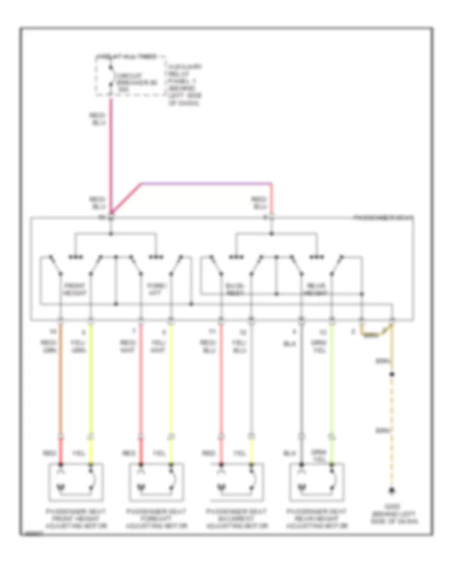
Passenger Seat Wiring Diagram, with Driver Memory Seat for Audi 100 CS 1994
List of elements for Passenger Seat Wiring Diagram, with Driver Memory Seat for Audi 100 CS 1994:
- Auxiliary relay panel 1 (behind left side of dash)
- Back- rest
- Circuit breaker 80 30a
- Fore/ aft
- Front height
- G202 (behind left side of dash)
- Hot at all times
- Passenger seat
- Passenger seat backrest adjusting motor
- Passenger seat fore/aft adjusting motor
- Passenger seat front height adjusting motor
- Passenger seat rear height adjusting motor
- Rear height
- Red
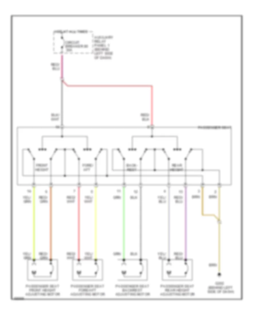
Passenger Seat Wiring Diagram, without Driver Memory Seat for Audi 100 CS 1994
List of elements for Passenger Seat Wiring Diagram, without Driver Memory Seat for Audi 100 CS 1994:
- Auxiliary relay panel 1 (behind left side of dash)
- Back- rest
- Circuit breaker 80 30a
- Fore/ aft
- Front height
- G202 (behind left side of dash)
- Hot at all times
- Passenger seat
- Passenger seat backrest adjusting motor
- Passenger seat fore/aft adjusting motor
- Passenger seat front height adjusting motor
- Passenger seat rear height adjusting motor
- Rear height
POWER TOP/SUNROOF
Sunroof Wiring Diagram, with Automatic Preselect for Audi 100 CS 1994
List of elements for Sunroof Wiring Diagram, with Automatic Preselect for Audi 100 CS 1994:
- (behind left side of i/p)
- 15a
- Auxiliary relay panel 1 (behind left side of i/p)
- Auxiliary relay panel 2 (left kick panel)
- Central electric panel (behind left side of i/p)
- Central locking/ alarm system/ interior light delay control module
- Circuit breaker 20a
- Fuse 14 15a
- Fuse panel
- G202 (behind left side of i/p)
- Hot at all times
- Hot in run or acc
- Nca
- Power sunroof control unit
- Power window control module
- Power windows system
- Solid state
- Sunroof motor
- Sunroof regulator
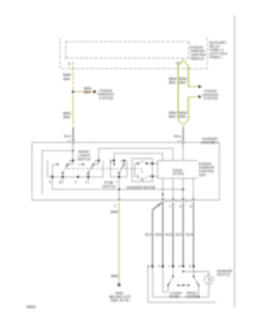
Sunroof Wiring Diagram, with Tilt/Slide for Audi 100 CS 1994
List of elements for Sunroof Wiring Diagram, with Tilt/Slide for Audi 100 CS 1994:
- Auxiliary relay panel 2 (left kick panel)
- Close/ raise
- G202 (behind left side of i/p)
- Nca
- Open/ lower
- Power sunroof control unit
- Power window control module
- Power windows system
- Raise/ lower switch
- Solid state
- Stop switch
- Sunroof assembly
- Sunroof motor
- Sunroof switch
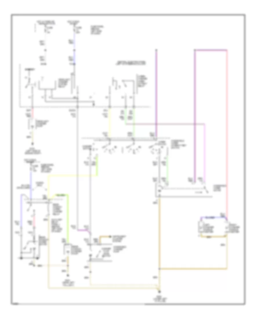
POWER WINDOWS
Power Windows Wiring Diagram (100 Wiring Diagram 1 Of 2) for Audi 100 CS 1994
List of elements for Power Windows Wiring Diagram (100 Wiring Diagram 1 Of 2) for Audi 100 CS 1994:
-
- 75x
- All times
- Automatic window closing relay
- Auxiliary relay panel 1 (behind left side of i/p)
- Auxiliary relay panel 2 (left kick panel)
- Central electric panel (behind left side of i/p)
- Central locking/ alarm system/ interior light delay control module
- Circuit breaker 30a
- Country specific version
- Driver's door handle alarm switch
- Ex. country specific version
- Front
- Fuse 15a
- Fuse panel (behind left side of i/p)
- G202 (left i/p)
- Hot at
- Hot at all times
- Interior
- Left front door contact switch
- Light
- Load reduc- tion relay
- Motor
- Passenger's door handle alarm switch
- Power window control module
- Red
- Right front door contact switch
- Seat belt warning control module
- Sunroof
- W/ anti- theft
- W/o anti- theft
Power Windows Wiring Diagram (100 Wiring Diagram 2 Of 2) for Audi 100 CS 1994
List of elements for Power Windows Wiring Diagram (100 Wiring Diagram 2 Of 2) for Audi 100 CS 1994:
-
- Anti-theft system (door lock switch)
- Interior lights system
- Left front door window motor
- Left front window switch
- Left rear door window motor
- Left rear door window switch (center console)
- Left rear door window switch (door)
- Rear cigar lighter
- Right front door window motor
- Right front door window switch (center console)
- Right front door window switch (door)
- Right rear door window motor
- Right rear door window switch (center console)
- Right rear door window switch (door)
- Sunroof motor
- Window lockout switch
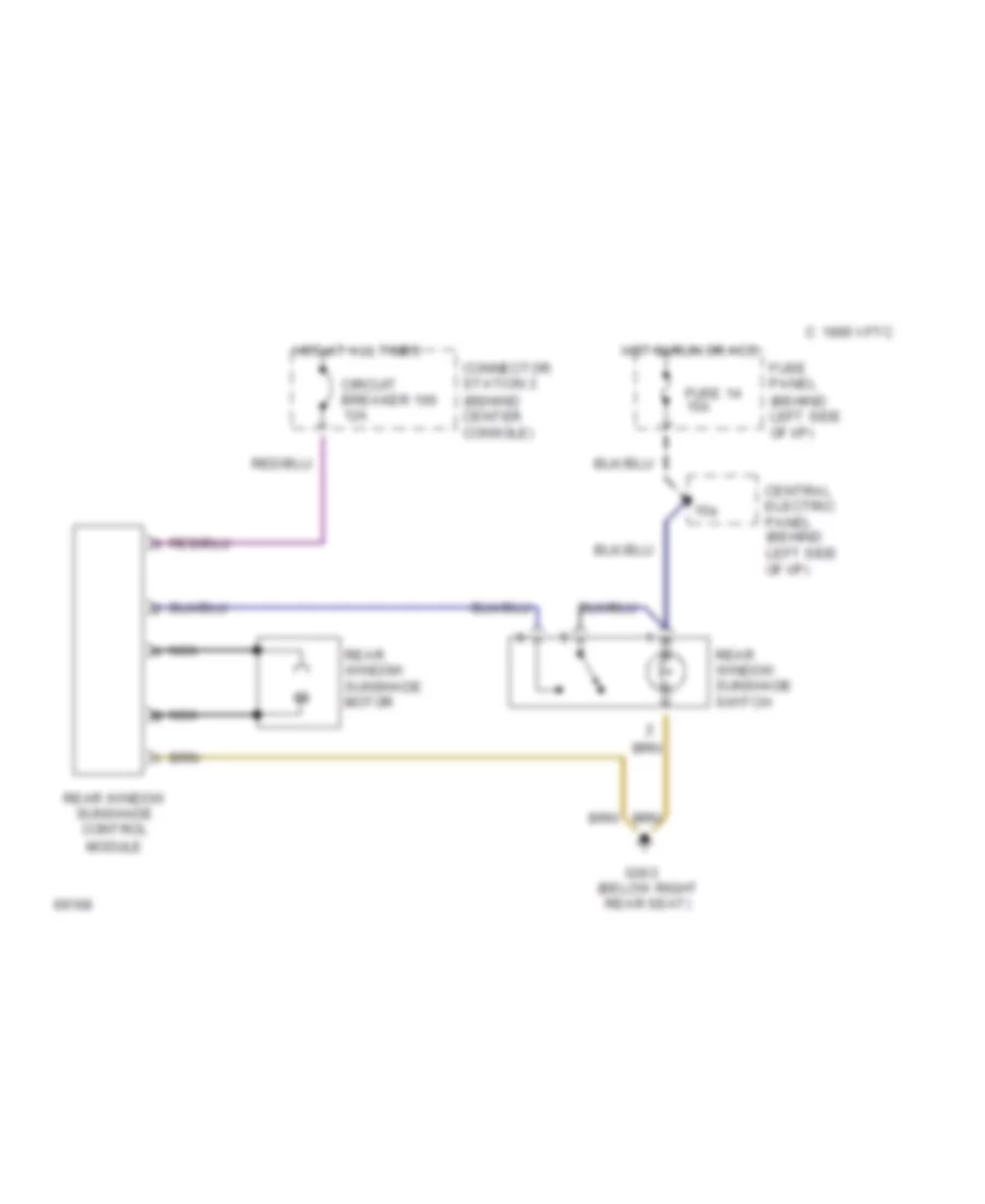
Rear Window Sun Shade Wiring Diagram for Audi 100 CS 1994
List of elements for Rear Window Sun Shade Wiring Diagram for Audi 100 CS 1994:
- (behind center console)
- (behind left side of i/p)
- 15a
- C 1995 vftc
- Central electric panel (behind left side of i/p)
- Circuit breaker 100 12a
- Connector station 3
- Fuse 14 15a
- Fuse panel
- G303 (below right rear seat)
- Hot at all times
- Hot in run or acc
- Nca a
- Nca b
- Rear window sunshade control module
- Rear window sunshade motor
- Rear window sunshade switch
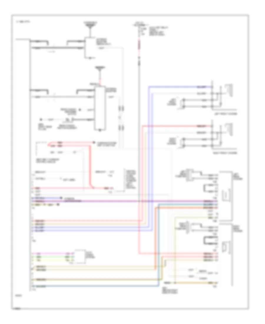
RADIO
Radio Wiring Diagram for Audi 100 CS 1994
List of elements for Radio Wiring Diagram for Audi 100 CS 1994:
- (not used)
- 1995 vftc c
- 2/85
- 9/r
- Antenna
- Antenna booster
- Antenna booster (sedan only)
- Auto check system
- Auxiliary relay panel 1 (behind left side of dash)
- Central locking/ alarm system/ interior light delay control
- G201 (behind right side of dash)
- G905 (right rear pillar)
- Hot at all times
- Interior lights system
- Left front woofer
- Left rear tweeter
- Left rear woofer
- Nca
- Radio
- Rear window defogger switch
- Rear window heating element
- Red
- Right front woofer
- Right rear tweeter
- Right rear woofer
- Seat belt warning control module
- Sedan
- T10
- T12
- T14
- T16
- T1i
- T2r
- T2s
- T4e
- T4f
- T5b
- T5c
- T8b
- Wagon
- Warning system (key in ignition)
- Windshield antenna
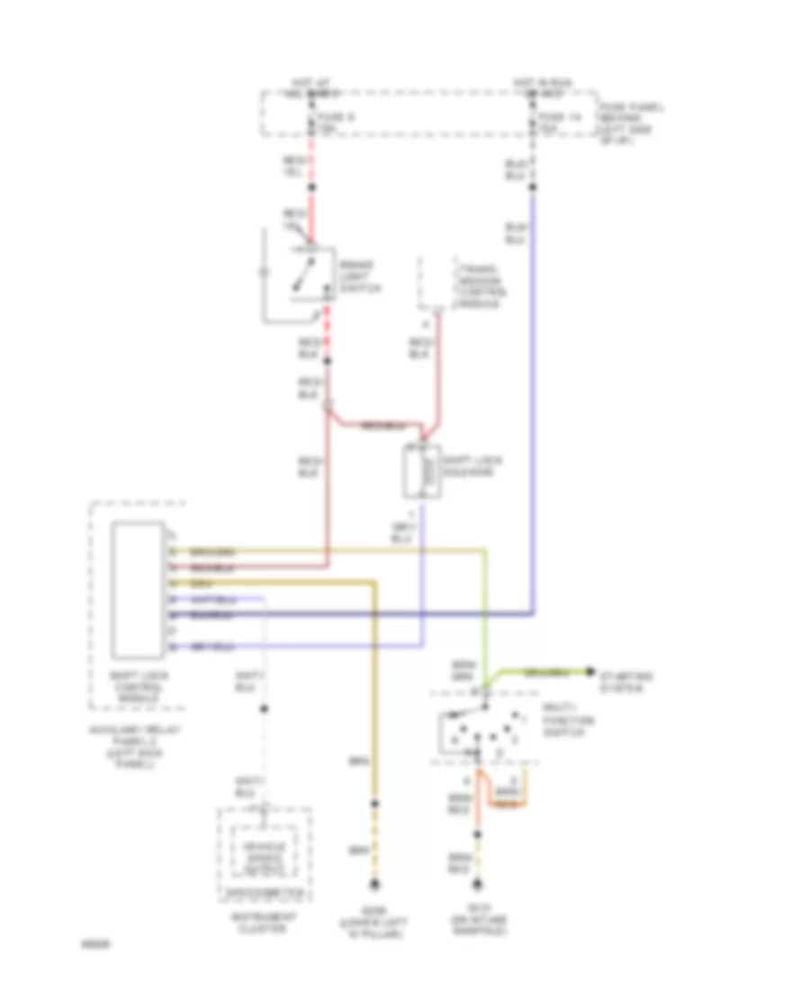
SHIFT INTERLOCK
Shift Interlock Wiring Diagram for Audi 100 CS 1994
List of elements for Shift Interlock Wiring Diagram for Audi 100 CS 1994:
-
- Auxiliary relay panel 2 (left kick panel)
- Brake light switch
- Cluster
- Function switch
- Fuse 14 15a
- Fuse 9 10a
- Fuse panel (behind left side of i/p)
- G131 (on intake manifold)
- G200 (lower left "a" pillar)
- Hot at all times
- Hot in run or acc
- Instrument
- Multi-
- Shift lock control module
- Shift lock solenoid
- Speedometer
- Starting system
- Trans- mission control module
- Vehicle speed output
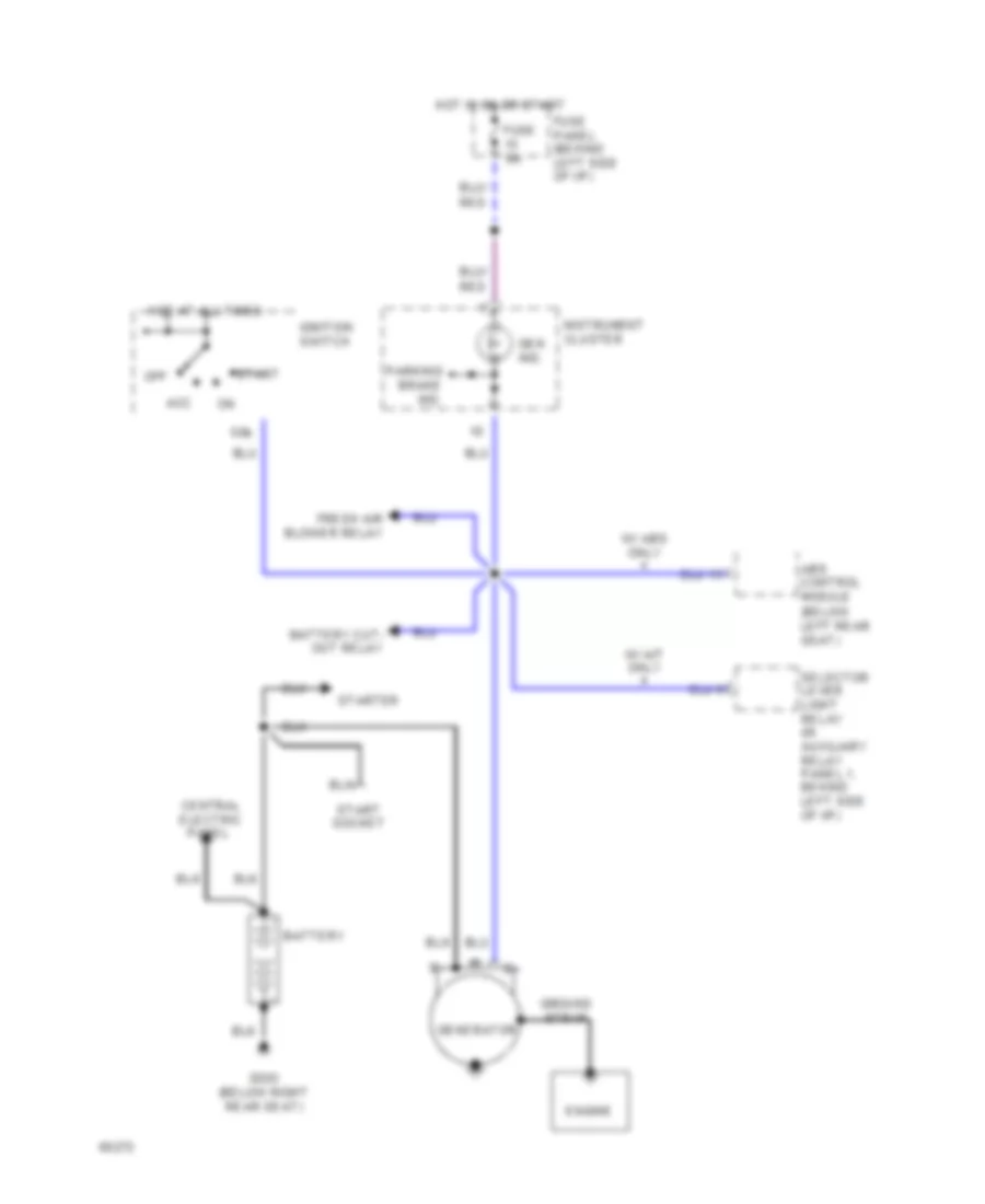
STARTING/CHARGING
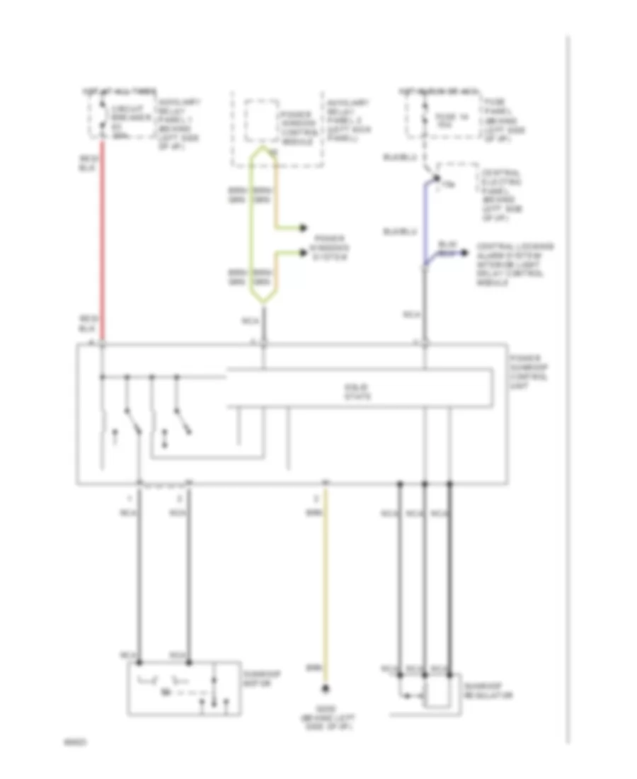
Charging Wiring Diagram for Audi 100 CS 1994
List of elements for Charging Wiring Diagram for Audi 100 CS 1994:
- (below left rear seat)
- 50b
- Abs control module
- Acc
- Battery
- Battery cut- out relay
- Central electric
- Engine
- Fresh air blower relay
- Fuse 5a
- Fuse panel (behind left side of i/p)
- G303 (below right rear seat)
- Gen ind.
- Generator
- Ground strap
- Hot at all times
- Hot in on or start
- Ignition switch
- Instrument cluster
- Off
- Panel
- Parking brake ind.
- Selector lever light relay (in auxiliary relay panel 1, behind left side of i/p)
- Start
- Start socket
- Starter
- W/ a/t only
- W/ abs only
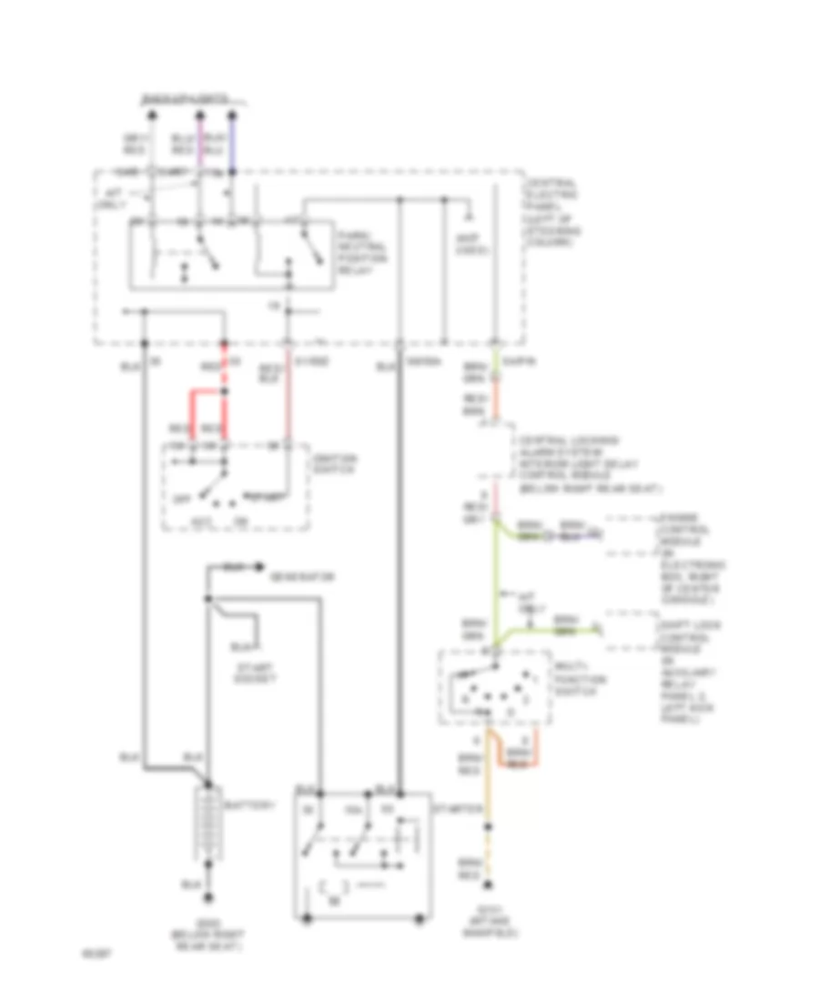
Starting Wiring Diagram for Audi 100 CS 1994
List of elements for Starting Wiring Diagram for Audi 100 CS 1994:
- (below right rear seat)
- (not used)
- 15a
- 15a
- A/t
- A/t only
- Acc
- Back-up lights
- Battery
- Central electric panel (left of steering column)
- Central locking/ alarm system/ interior light delay control module
- Engine control module (in electronic box, right of center console)
- Function switch
- G131 (intake manifold)
- G303 (below right rear seat)
- Generator
- Ignition switch
- Multi-
- Off
- Only
- Park/ neutral position relay
- Red
- S1/50z
- S4/b
- S4/p/n
- S4/rf
- S6/50a
- Shift lock control module (in auxiliary relay panel 2, left kick panel)
- Start
- Start socket
- Starter
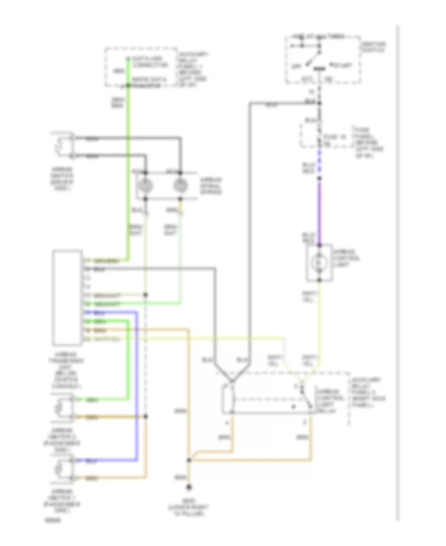
SUPPLEMENTAL RESTRAINTS
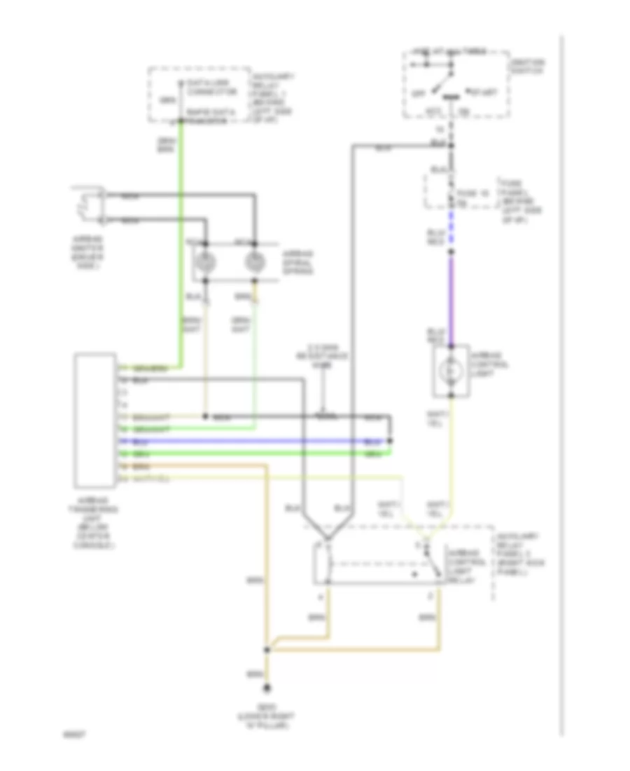
Supplemental Restraints Wiring Diagram, Driver"s & Passenger"s for Audi 100 CS 1994
List of elements for Supplemental Restraints Wiring Diagram, Driver"s & Passenger"s for Audi 100 CS 1994:
-
-
- Acc
- Airbag control light
- Airbag control light relay
- Airbag igniter (driver side)
- Airbag igniter 1 (passenger side)
- Airbag igniter 2 (passenger side)
- Airbag spiral spring
- Airbag triggering unit (below center console)
- Auxiliary relay panel 1 (behind left side of i/p)
- Auxiliary relay panel 3 (right kick panel)
- Connector
- Data link
- Fuse 15 5a
- Fuse panel (behind left side of i/p)
- G203 (lower right "a" pillar)
- Hot at all times
- Ignition switch
- Nca
- Off
- Rapid data
- Start
- Transfer
Supplemental Restraints Wiring Diagram, Driver"s for Audi 100 CS 1994
List of elements for Supplemental Restraints Wiring Diagram, Driver"s for Audi 100 CS 1994:
-
-
- 2.5 ohm resistance wire
- Acc
- Airbag control light
- Airbag control light relay
- Airbag igniter (driver side)
- Airbag spiral spring
- Airbag triggering unit (below center console)
- Auxiliary relay panel 1 (behind left side of i/p)
- Auxiliary relay panel 3 (right kick panel)
- Connector
- Data link
- Fuse 15 5a
- Fuse panel (behind left side of i/p)
- G203 (lower right "a" pillar)
- Hot at all times
- Ignition switch
- Nca
- Off
- Rapid data
- Start
- Transfer
TRANSMISSION
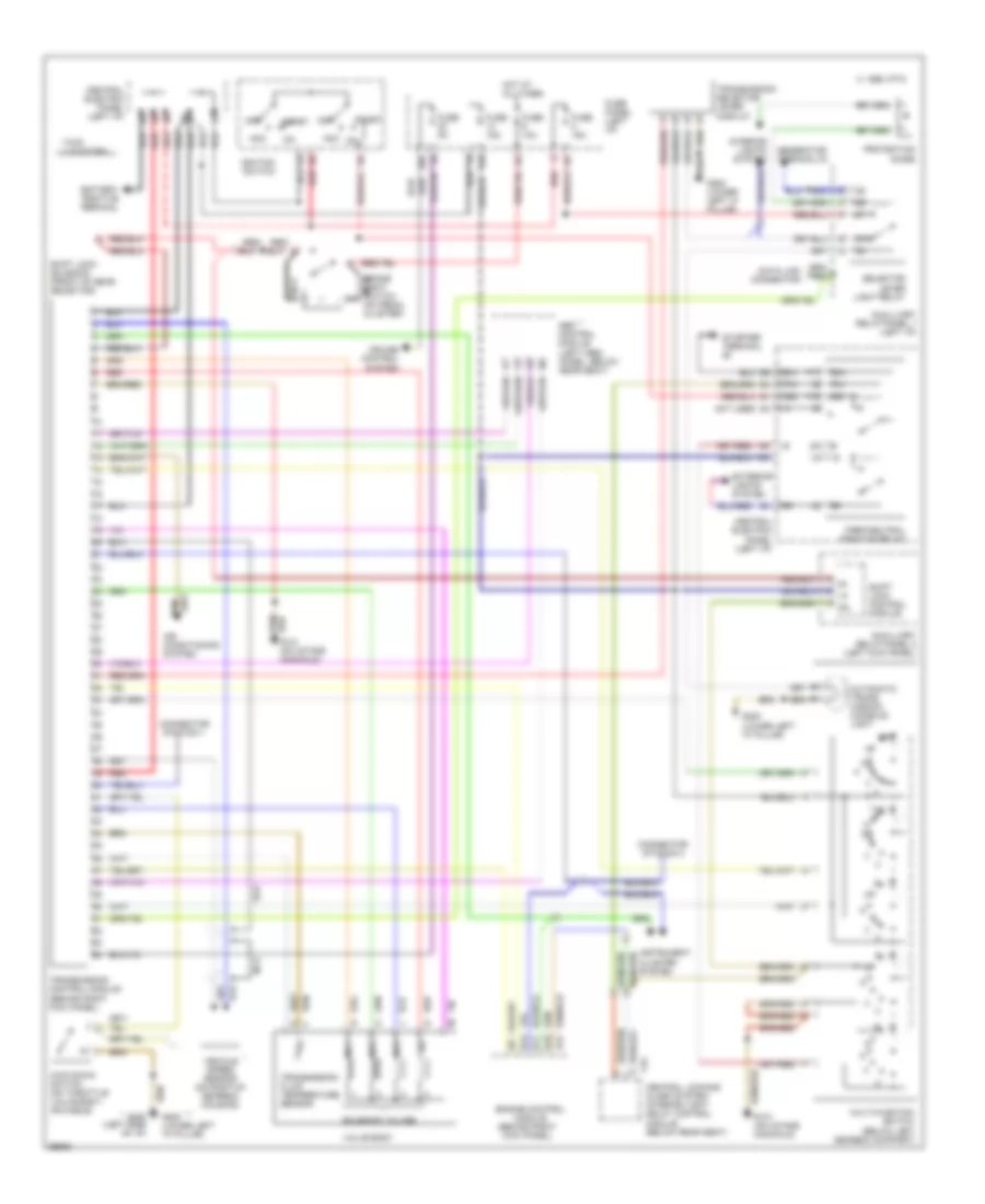
A/T Wiring Diagram for Audi 100 CS 1994
List of elements for A/T Wiring Diagram for Audi 100 CS 1994:
- (below left gearbox support)
- (left heel panel, below rear seat)
- * *
- * fwd ** quattro
- 14a
- 15a
- 1995 vftc c
- 20a
- 50a
- 50z
- 87a
- Abs control module
- Acc
- Acc on
- Air conditioning system
- Automatic trans- mission console light
- Auxilliary relay panel 1 (left i/p)
- Auxilliary relay panel 2 (left kick panel)
- B10
- B11
- B12
- B13
- Battery positive terminal
- Brake light switch (on pedal cluster)
- Central electric panel (left i/p)
- Central locking/ alarm system/ interior light delay control module (below rear seat)
- Connector station 1
- Connector station 3
- Cruise control system
- Data link connector
- Engine control module (behind right kick panel)
- Exterior lights system
- Fuse 10a
- Fuse 15a
- Fuse 5a
- Fuse panel (left i/p)
- G131 (on intake manifold)
- G200 (lower left "a" pillar)
- Generator terminal d+
- Hot at all times
- Ignition switch
- Instrument cluster system
- Interior lights system
- Kick down switch (on throttle valve body, or cable)
- Multi-function switch
- Mv1
- Mv2
- Mv3
- Nca
- Not used
- Off
- P/n
- Park/neutral position relay
- Protection diode
- Red
- Red/
- Selector lever light relay
- Shift lock control module
- Shift lock solenoid (front of gear selector)
- Solenoid valves
- Start
- Starter terminal
- T16
- Transmission control module (behind right kick panel)
- Transmission fluid temperature sensor
- Transmission selector lever display
- Valve body
- Vehicle speed sensor (on right of gearbox housing)
Differential Lock Wiring Diagram, Quattro for Audi 100 CS 1994
List of elements for Differential Lock Wiring Diagram, Quattro for Audi 100 CS 1994:
- (lower left "a" pillar)
- 14a
- Abs combi relay
- Cluster
- Diff. lock ind.
- Differ- ential lock switch
- Differential lock control
- Fuse 14 15a
- Fuse panel (behind left side of i/p)
- G200
- Hot in on or start
- Ill.
- Instrument
- Interior lights system (rheostat)
- Module
- Rear diff. lock ind.
- Rear differential lock switch
- Rear differential lock switch illumination/ indicator
- Solid state
- Speedo- meter
TRUNK, TAILGATE, FUEL DOOR
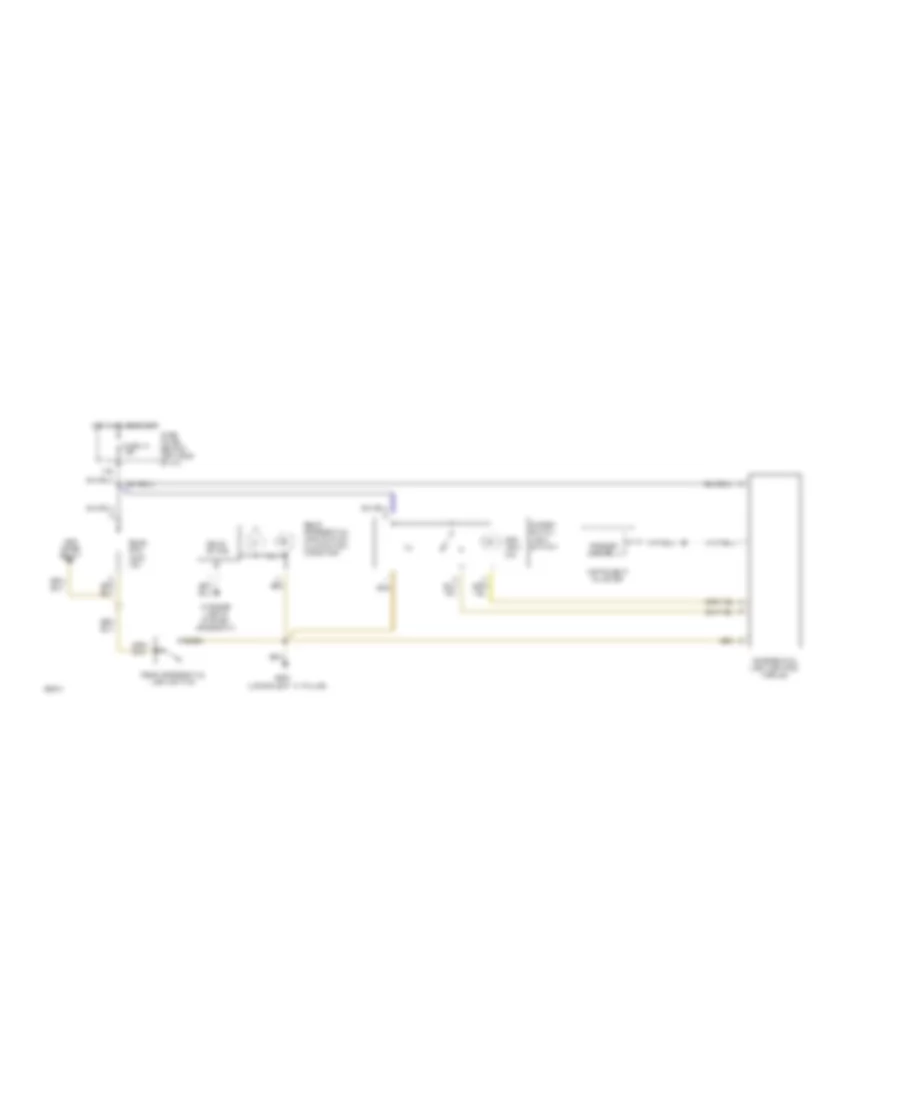
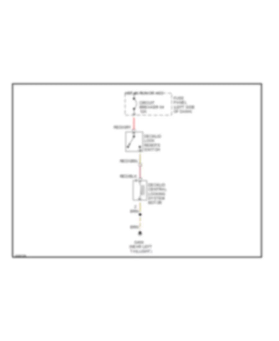
Trunk, Tailgate, Fuel Door Wiring Diagram for Audi 100 CS 1994
List of elements for Trunk, Tailgate, Fuel Door Wiring Diagram for Audi 100 CS 1994:
- Circuit breaker 64 12a
- Decklid central locking system motor
- Decklid lock remote switch
- Fuse panel (left side of dash)
- G404 (near left taillight)
- Hot in run or acc
WARNING SYSTEMS
Warning Systems Wiring Diagram for Audi 100 CS 1994
List of elements for Warning Systems Wiring Diagram for Audi 100 CS 1994:
-
-
- 86s
- Alarm system/
- Antenna booster
- Central electric panel (behind left side of i/p)
- Central locking/
- Control module
- Exterior
- Fuse 14 15a
- Fuse 7 5a
- Fuse panel (behind left side of i/p)
- G200 (left kick panel)
- Head
- Hot at all times
- Hot in on or acc
- Ignition switch
- Interior light delay
- Key-in- ignition
- Left front door contact switch
- Left seat belt switch
- Light switch
- Lights system
- Memory seat control module
- Off
- Park
- Radio
- Red
- Seat belt warning control module
- Seat belt warning indicator
WIPER/WASHER
Wiper/Washer Wiring Diagram for Audi 100 CS 1994
List of elements for Wiper/Washer Wiring Diagram for Audi 100 CS 1994:
- (left of steering column)
- 58a
- 75a
- Auxiliary relay panel 1 (behind left side of dash)
- Battery
- Central electric panel
- Fuse 15a
- Fuse 25a
- Fuse 5a
- Fuse panel (behind left side of dash)
- G100 (left side of engine compt)
- G200 (lower left "a" pillar)
- G404 (near left taillight)
- Headlight washer pump
- Headlight washer system relay
- Headlights on
- Hot in run
- Hot w/ park or
- Instrument cluster system
- Left washer nozzle heater
- Nca
- Or acc
- Rear window washer pump
- Rear window wiper motor
- Rear window wiper/ washer relay
- Right washer nozzle heater
- S2/ 31b
- S2/ 53e
- S2/53c
- S2/j
- S5/p
- Wagon only
- Washer fluid level switch
- Washer switch
- Windshield washer pump
- Windshield wiper intermittent switch
- Windshield wiper motor
- Wiper switch
- Wiper/ washer inter- mittent relay

 Čeština
 Dansk
Dansk Deutsch
 Ελληνικά
 English
 English
 Suomi
Suomi Français
 Français
 עברית
עברית Hrvatski
 Magyar
 Italiano
 日本語
日本語 한국어
한국어 Nederlands
 Polski
 Português
 Português
 Română
 Русский
 Slovenčina
 Slovenščina
 Svenska
 Türkçe
 中文 (中国)