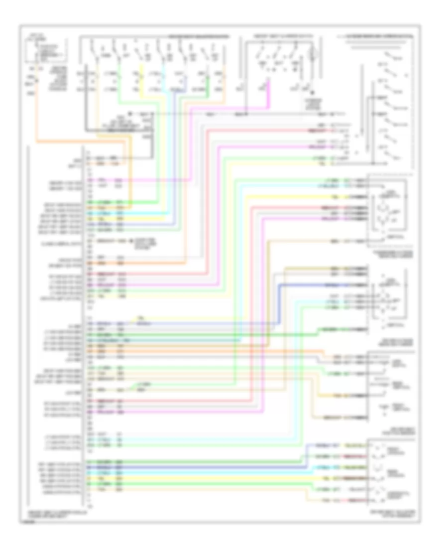
AIR CONDITIONING
Automatic A/C Wiring Diagram for Buick Rendezvous Ultra 2004
 https://portal-diagnostov.com/license.html
Automotive Electricians Portal FZCO
Automotive Electricians Portal FZCO
https://portal-diagnostov.com/license.html
https://portal-diagnostov.com/license.html
Automotive Electricians Portal FZCO
Automotive Electricians Portal FZCO
List of elements for Automatic A/C Wiring Diagram for Buick Rendezvous Ultra 2004:
- (fuel injector harness, 5 cm from c102)
- (i/p harness, right side of dash, 4 cm from
- (i/p harness, center of dash, 4 cm from blower motor resistor breakout)
- (i/p harness, right side of dash, 24 cm from stoplamp switch breakout)
- (top right side of radiator, 6 cm from starter breakout)
- +5v reference
- 5 volt ref
- A/c compressor clutch
- A/c clu fuse 10a
- A/c clu relay 51
- A/c compressor clutch diode
- A/c press signal
- A/c refrigerant pressure sensor (left side of engine compartment, below air cleaner assembly)
- A10
- A11
- A12
- B10
- B11
- B12
- Bat
- Blower motor (part of hvac module, behind glove box)
- Blower motor control processor (part of hvac module, behind glove box, in front of blower motor)
- Center console fuse block (in floor console)
- Class 2 serial
- Comp control
- Computer data lines system
- Cool fan 1 fuse 30a
- Cool fan 1 relay 61
- Cool fan 2 fuse 30a
- Cool fan 2 relay 58
- Cool fan 3 relay 60
- Defog rly ctrl
- Defogger system
- Ect sensor
- Engine controls system
- Engine coolant temperature (ect) sensor (on top rear of engine, near thermostat housing)
- Evap temp sig
- Evaporative temperature sensor (in hvac module, mounted to evaporator coil)
- F10
- G100 (right side of engine compartment, on top of front end upper cross member)
- G117 (engine compartment, on bell housing, above starter)
- G200 (right side of dash, on underside of cross-car beam)
- Gnd
- H10
- H12
- Hi spd fan ctrl
- Hot at all times
- Hot in run
- Hvac control module (center of dash, below radio)
- Hvac/radio harness breakout)
- I/p lamp sply
- Ign 3 fuse 40a
- Ign 3 hvac fuse 10a c1
- Ign 3 voltage
- Ignition relay 59 (3.4l) ptrain relay 59 (3.6l)
- Interior lights system
- Ip mdl fuse 10a
- J10
- J12
- Left air temperature actuator (left side of hvac module)
- Left cooling fan (mounted to rear left side of radiator)
- Lft temp dr ctrl
- Lft temp dr sig
- Lo spd fan ctrl
- Logic
- Low ref
- Low reference
- Mode actuator (on left end of hvac assembly)
- Mode dr ctrl
- Mode dr sig
- Mtr spd ctrl
- Mtr spd sig
- N11
- Power distribution system
- Powertrain control module (pcm) (at left side of engine compartment, in air cleaner assembly)
- Recirc dr ctrl
- Recirculation actuator (on right end of hvac assembly)
- Red
- Right air temperature actuator (right side of hvac module)
- Right cooling fan (mounted to rear right side of radiator)
- Rt temp dr ctrl
- Rt temp dr sig
- S105
- S110
- S204
- S205
- S213
- Serial data
- Splice pack sp250
- Sunload sensor (center of dash, mounted to trim plate, near windshield defrost vent)
- Sunload sig
- Tan
- Underhood fuse block (front of right wheelhouse, above battery)
Compressor Wiring Diagram, with Auto A/C for Buick Rendezvous Ultra 2004
List of elements for Compressor Wiring Diagram, with Auto A/C for Buick Rendezvous Ultra 2004:
- +5v reference
- A/c compressor clutch
- A/c clu fuse 10a
- A/c clu relay 51
- A/c compressor clutch diode
- A/c press sig
- A/c refrigerant pressure sensor (left side of engine compartment, below air cleaner assembly)
- A10
- A11
- A12
- B10
- Bat
- Center console fuse block (in floor console)
- Class 2 serial
- Comp control
- Computer data lines system
- G117 (engine compartment, on bell housing, above starter)
- G200 (right side of dash, on underside of cross-car beam)
- Gnd
- Hot at all times
- Hot in run
- Hvac control module (center of dash, below radio)
- Ign 3 hvac fuse 10a
- Ign 3 voltage
- Ignition relay 59 (3.4l) ptrain relay 59 (3.6l)
- Ip mdl fuse 10a
- Low reference
- N11
- Power distribution system
- Powertrain control module (pcm) (at left side of engine compartment, in air cleaner assembly)
- S213 (i/p harness, center of dash, 4 cm from blower motor resistor & auxiliary drop power connector main branch breakout)
- Serial data
- Underhood fuse block (front of right wheelhouse, above battery)
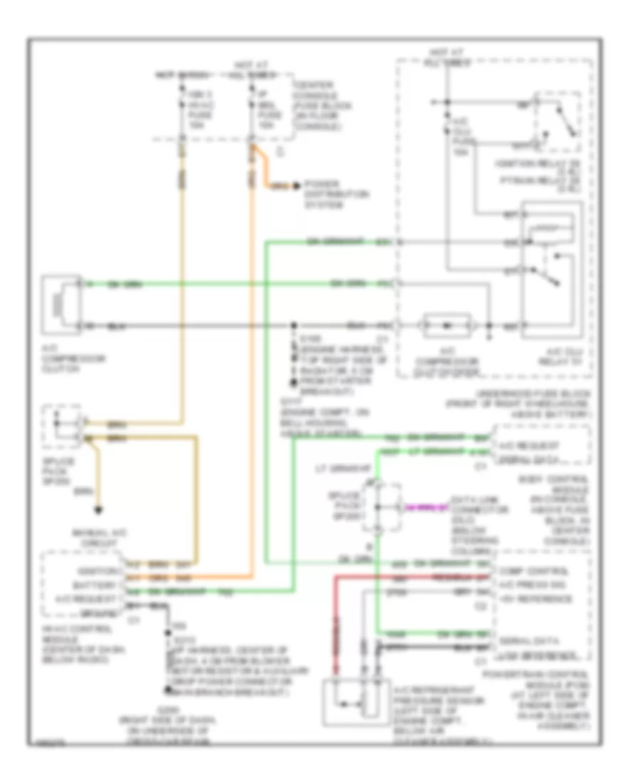
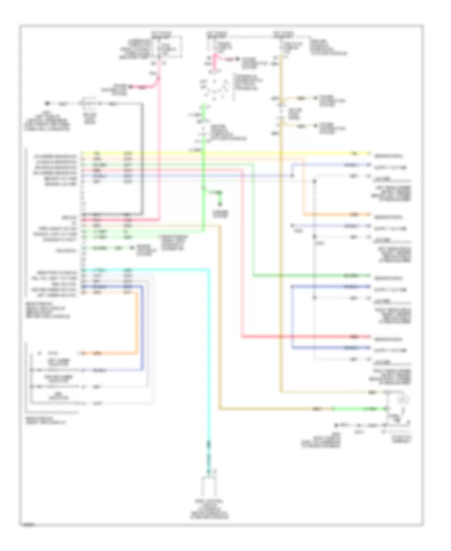
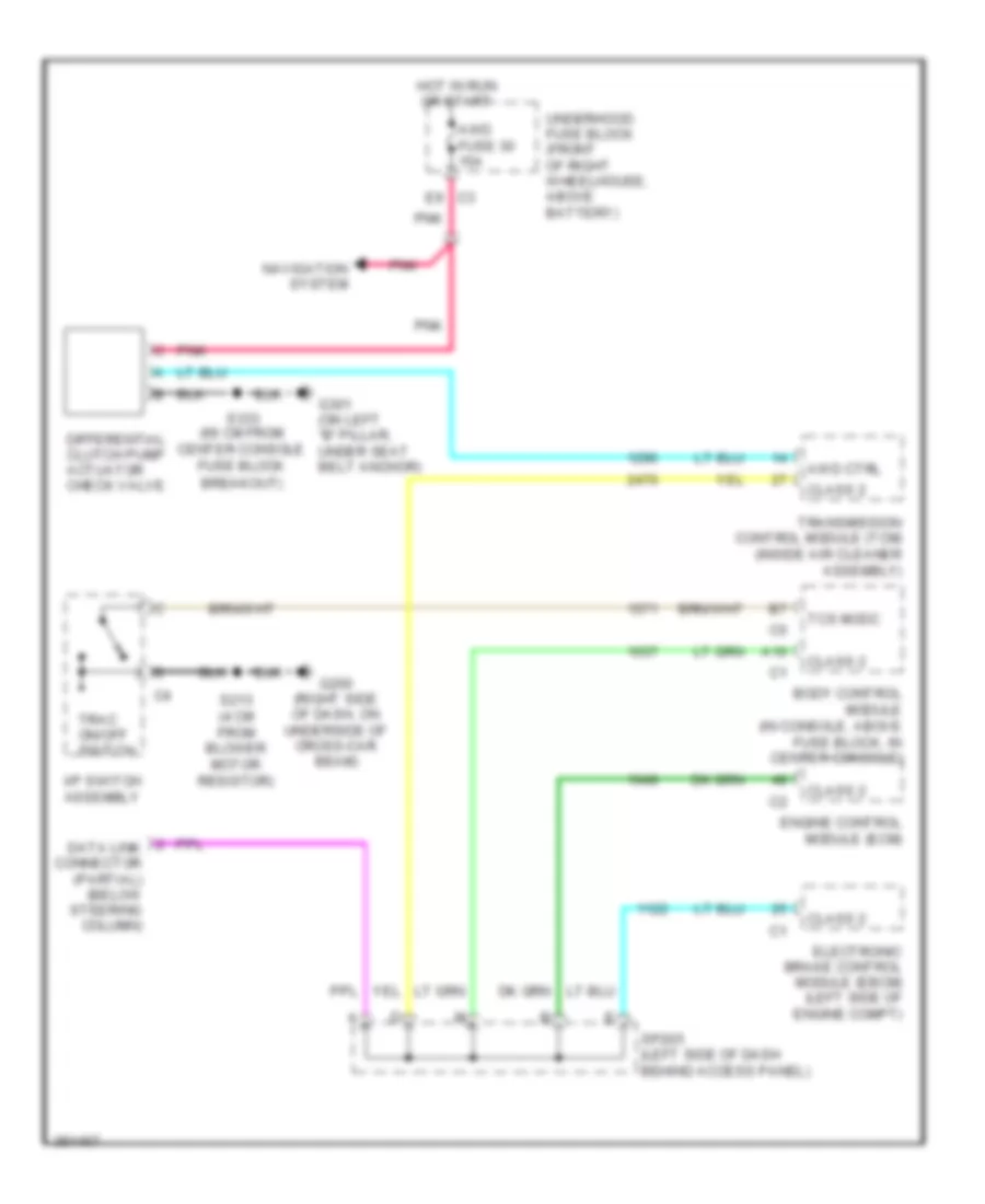
Compressor Wiring Diagram, with Manual A/C for Buick Rendezvous Ultra 2004
List of elements for Compressor Wiring Diagram, with Manual A/C for Buick Rendezvous Ultra 2004:
- +5v reference
- A/c compressor clutch
- A/c clu fuse 10a
- A/c clu relay 51
- A/c compressor clutch diode
- A/c press sig
- A/c refrigerant pressure sensor (left side of engine compt, below air cleaner assembly)
- A/c request
- A10
- B10
- Battery
- Body control module (in console, above fuse block, in center console)
- Center console fuse block (in floor console)
- Comp control
- Data link connector (dlc) (below steering column)
- Drop power connector main branch breakout)
- G117 (engine compt, on bell housing, above starter)
- G200 (right side of dash, on underside of cross-car beam)
- Ground
- Hot at all times
- Hot in run
- Hvac control module (center of dash, below radio)
- Ign 3 hvac fuse 10a
- Ignition
- Ignition relay 59 (3.4l) ptrain relay 59 (3.6l)
- Ip mdl fuse 10a
- Low reference
- Manual a/c circuit
- N11
- Power distribution system
- Powertrain control module (pcm) (at left side of engine compt, in air cleaner assembly)
- S105 (engine harness, top right side of radiator, 6 cm from starter breakout)
- Serial data
- Splice pack sp205
- Splice pack sp250
- Underhood fuse block (front of right wheelhouse, above battery)
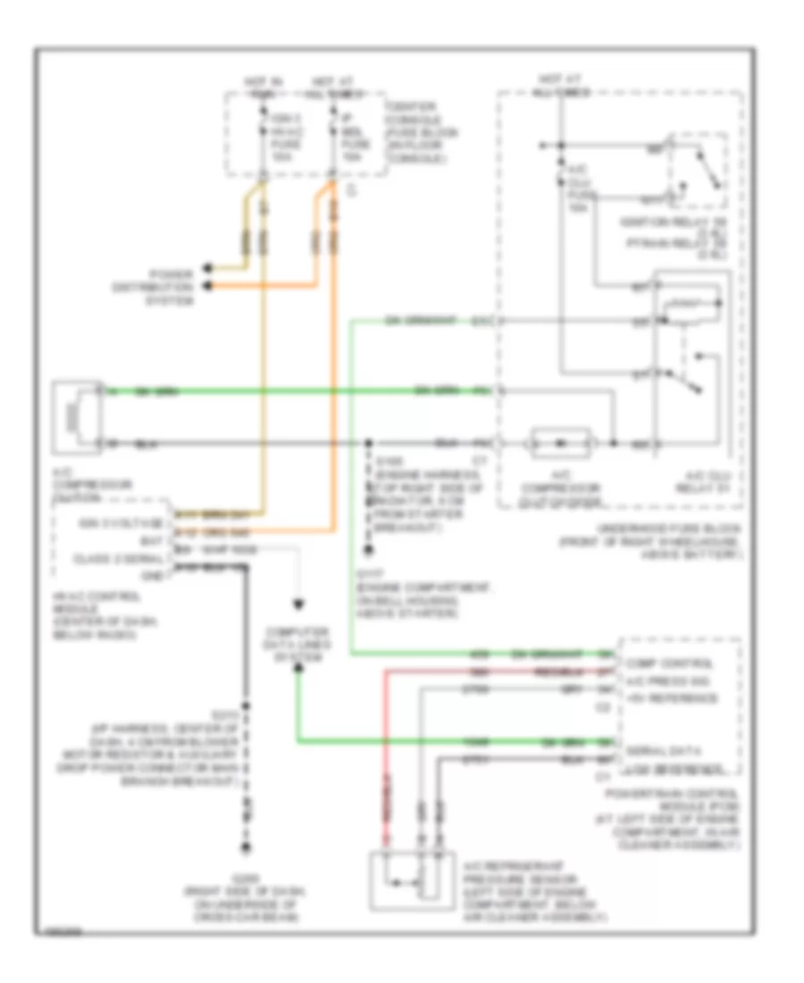
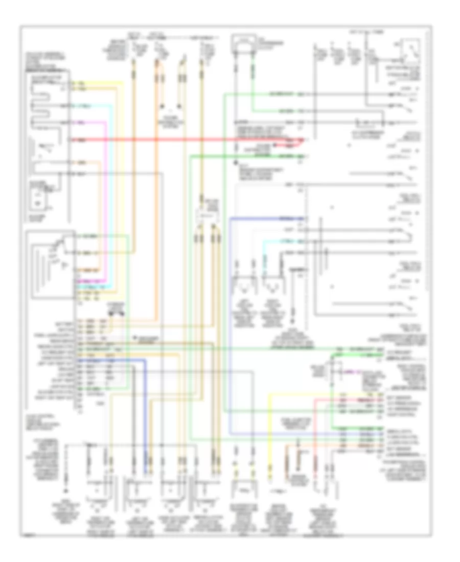
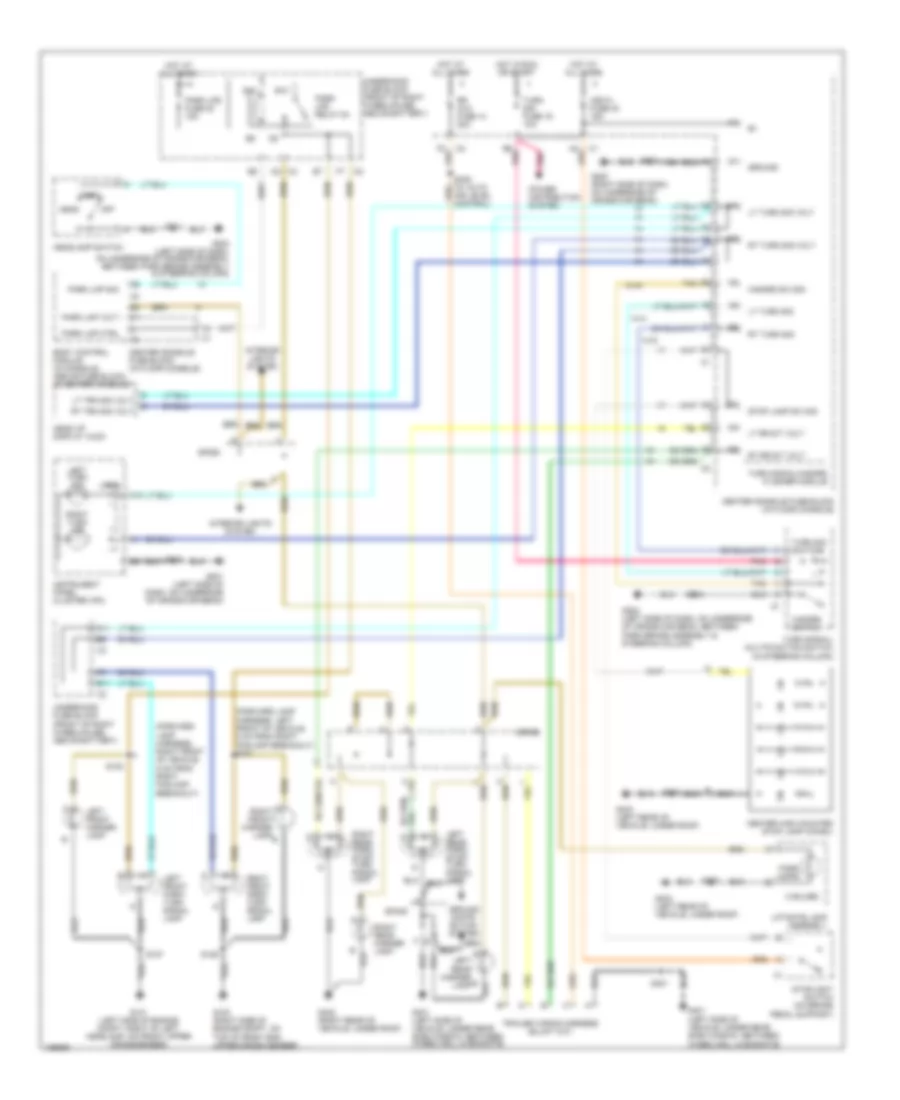
Manual A/C Wiring Diagram for Buick Rendezvous Ultra 2004
List of elements for Manual A/C Wiring Diagram for Buick Rendezvous Ultra 2004:
- (engine harn, top right side of radiator, 6 cm from starter breakout)
- (fuel injector harness, 5 cm from c102)
- (i/p harness, center of dash, 4 cm from blower motor resistor & auxiliary drop power connector main branch breakout)
- (left side of hvac module)
- (on hvac assembly, in front of blower motor) blower motor resistor assembly
- (right side of hvac module)
- +5v reference
- A/c compressor clutch
- A/c clu fuse 10a
- A/c clu relay 51
- A/c compressor clutch diode
- A/c press signal
- A/c refrigerant pressure sensor (left side of engine compt, below air cleaner assembly)
- A/c request
- A/c request sig
- A10
- B10
- Battery
- Blower motor
- Blower motor relay
- Blower motor resistors
- Blower mtr ctrl
- Blwr fuse 25a
- Body control module (bcm) (in console, above fuse block, in center console)
- Center console fuse block (in floor console)
- Comp control
- Cool fan 1 fuse 30a
- Cool fan 1 relay 61
- Cool fan 2 fuse 30a
- Cool fan 2 relay 58
- Cool fan 3 relay 60
- Data link connector (below steering column)
- Defogger system
- Ect sensor
- Engine controls system
- Engine coolant temperature (ect) sensor (on top rear of engine, near thermostat housing)
- Evap temp
- Evaporative temperature sensor (in hvac module, mounted to evaporator coil)
- F10
- G100 (right side of engine compt, on top of front end upper cross member)
- G117 (engine compartment, on bell housing, above starter)
- G200 (right side of dash, on underside of cross-car beam)
- Ground
- H10
- H12
- Hi spd fan ctrl
- Hot at all times
- Hot in run
- Hvac control module (center of dash, below radio)
- Ign 3 fuse 40a
- Ign 3 hvac fuse 10a c1
- Ignition
- Ignition relay 59 (3.4l) ptrain relay 59 (3.6l)
- Interior lights system
- Ip mdl fuse 10a
- J10
- J12
- Lamp dim sig
- Left air temp act
- Left air temperature actuator
- Left cooling fan (mounted to rear left side of radiator)
- Lo spd fan ctrl
- Logic
- Low ref
- Low reference
- Mode actuator (on left end of hvac assembly)
- Mode door ctrl
- N11
- Off
- Power distribution system
- Powertrain control module (pcm) (at left side of engine compartment, in air cleaner assembly)
- Rear defog
- Recirc door ctrl
- Recirculation actuator (on right end of hvac assembly)
- Red
- Right air temp act
- Right air temperature actuator
- Right cooling fan (mounted to rear right side of radiator)
- S105
- S110
- S213
- Serial data
- Splice pack sp205
- Splice pack sp250
- Tan
- Underhood fuse block (front of right wheelhouse, above battery)
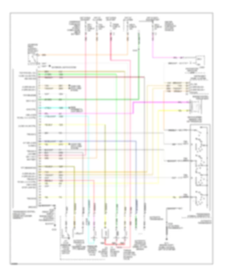
ANTI-LOCK BRAKES
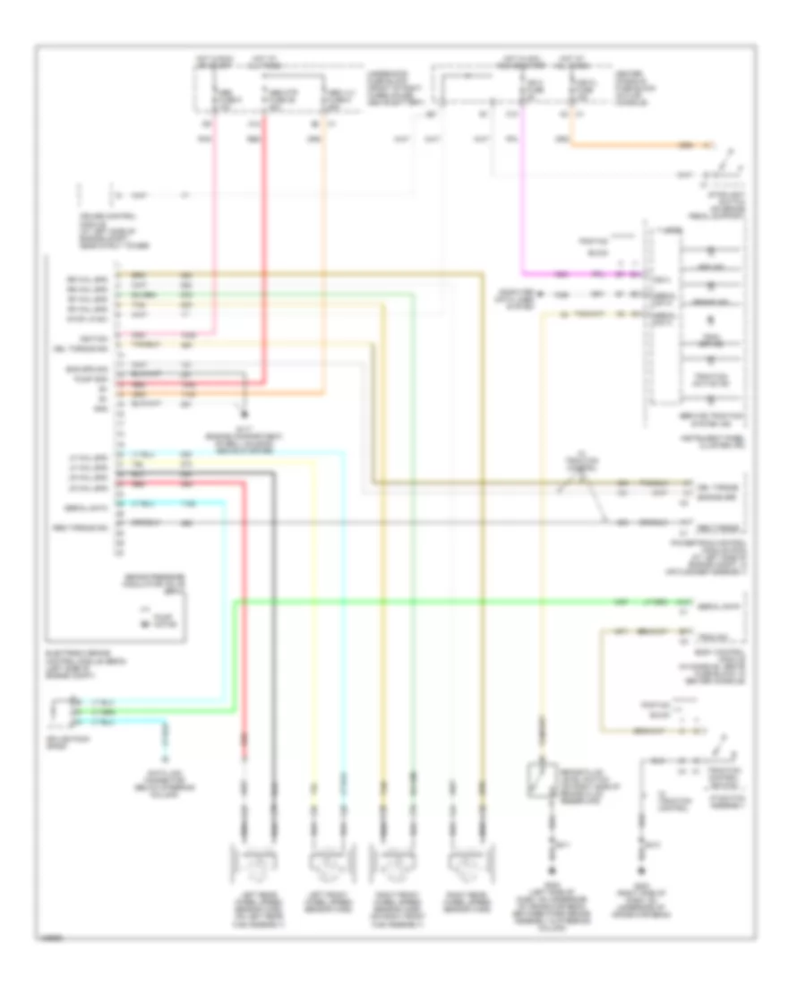
Anti-lock Brakes Wiring Diagram for Buick Rendezvous Ultra 2004
List of elements for Anti-lock Brakes Wiring Diagram for Buick Rendezvous Ultra 2004:
- A10
- A12
- Abs fuse 6 10a
- Abs ind
- Abs mtr fuse 36 40a
- Abs vlv fuse 9 25a
- Body control module (in console, above fuse block, in center console)
- Brake fluid level switch (on right side of brake fluid reservoir)
- Brake ind
- Brake pressure modulator valve (bpmv)
- Buick
- C10
- Center console fuse block (in flor console)
- Computer data lines system
- Cruise control module (at left side of engine compt, near strut tower)
- Data link connector (below steering column)
- Del torque
- Del torque sig
- Electronic brake control module (ebcm) (left side of engine compt)
- Eng spd sig
- Engine spd
- G117 (engine compartment, on bell housing, above starter)
- G200 (right side of dash, on underside of cross-car beam)
- G202 (left side of dash, on underside of cross-car beam, between park brake assembly & steering column)
- Gnd
- Hot at all times
- Hot in acc, run or start
- Hot in run or start
- Hzd fl fuse 15a
- I/p switch assembly
- Ign 0
- Ign 0 fuse 2a
- Ignition
- Instrument panel cluster (ipc)
- Left front wheel speed sensor (wss)
- Left rear wheel speed sensor (wss) (on left rear hub assembly)
- Lf whl spd
- Logic
- Lr whl spd
- Pnk
- Pontiac
- Powertrain control module (pcm) (at left side of engine compt, in air cleaner assembly)
- Pump gnd
- Pump motor
- Red
- Req torque
- Req torque sig
- Rf whl spd
- Right front wheel speed sensor (wss) (on right front hub assembly)
- Right rear wheel speed sensor (wss)
- Rr whl spd
- S211
- S213
- Serial data
- Service traction system ind
- Splice pack sp205
- Stop lp sw
- Stoplight switch (on brake pedal support)
- Tan
- Trac off ind
- Trac sw
- Traction active ind
- Traction control switch
- Underhood fuse block (front of right wheelhouse, above battery)
- W/ traction control
ANTI-THEFT
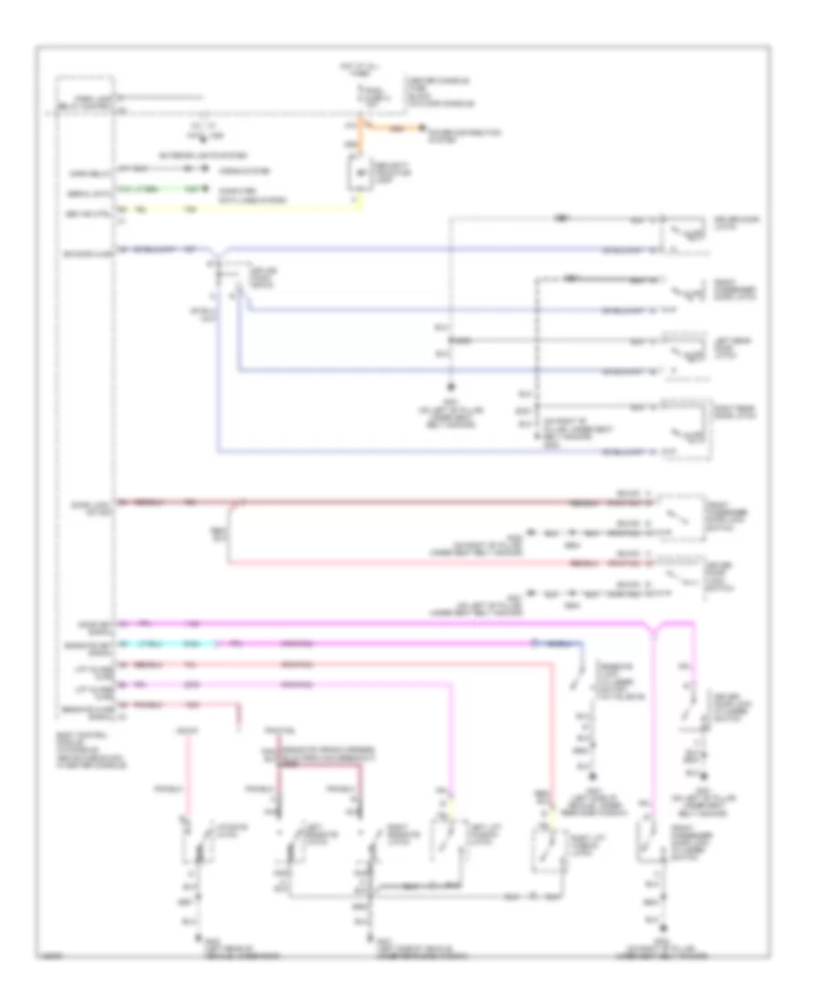
Forced Entry Wiring Diagram for Buick Rendezvous Ultra 2004
List of elements for Forced Entry Wiring Diagram for Buick Rendezvous Ultra 2004:
- (buick)
- (on right "b" pillar, under seat belt anchor) g302
- (pontiac)
- A10
- A11
- A4 door key signal
- A5 endgate key signal
- A8 lift glass ajar
- A9 endgate ajar signal
- Ajar
- B2 lift glass ajar
- Body control module (in console, above fuse block, in center console)
- Buick
- Center console fuse block (in floor console)
- Computer
- Data lines system
- Door lock/ sw sig
- Dr door ajar
- Driver door latch
- Driver door lock cylinder switch
- Driver door lock switch
- Endgate lock cylinder switch (in tailgate)
- Exterior lights system
- Front passenger door latch
- Front passenger door lock cylinder switch
- Front passenger door lock switch
- G301 (on left "b" pillar, under seat belt anchor)
- G302 (on right "b" pillar, under seat belt anchor)
- G401 (left side of vehicle, under rear side window)
- G403 (left rear of vehicle, under roof)
- Horn relay
- Horns system
- Hot at all times
- Ipmdl fuse 41 10a
- Left endgate latch
- Left lift window latch
- Left rear door latch
- Liftgate latch
- Nca
- Park lamp relay control c3
- Pontiac
- Power distribution system
- Right endgate latch
- Right lift window latch
- Right rear door latch
- S303
- S333
- S504
- S604
- S902
- S907
- Sec ind ctrl
- Security indicator lamp
- Serial data
- Splice pack sp315
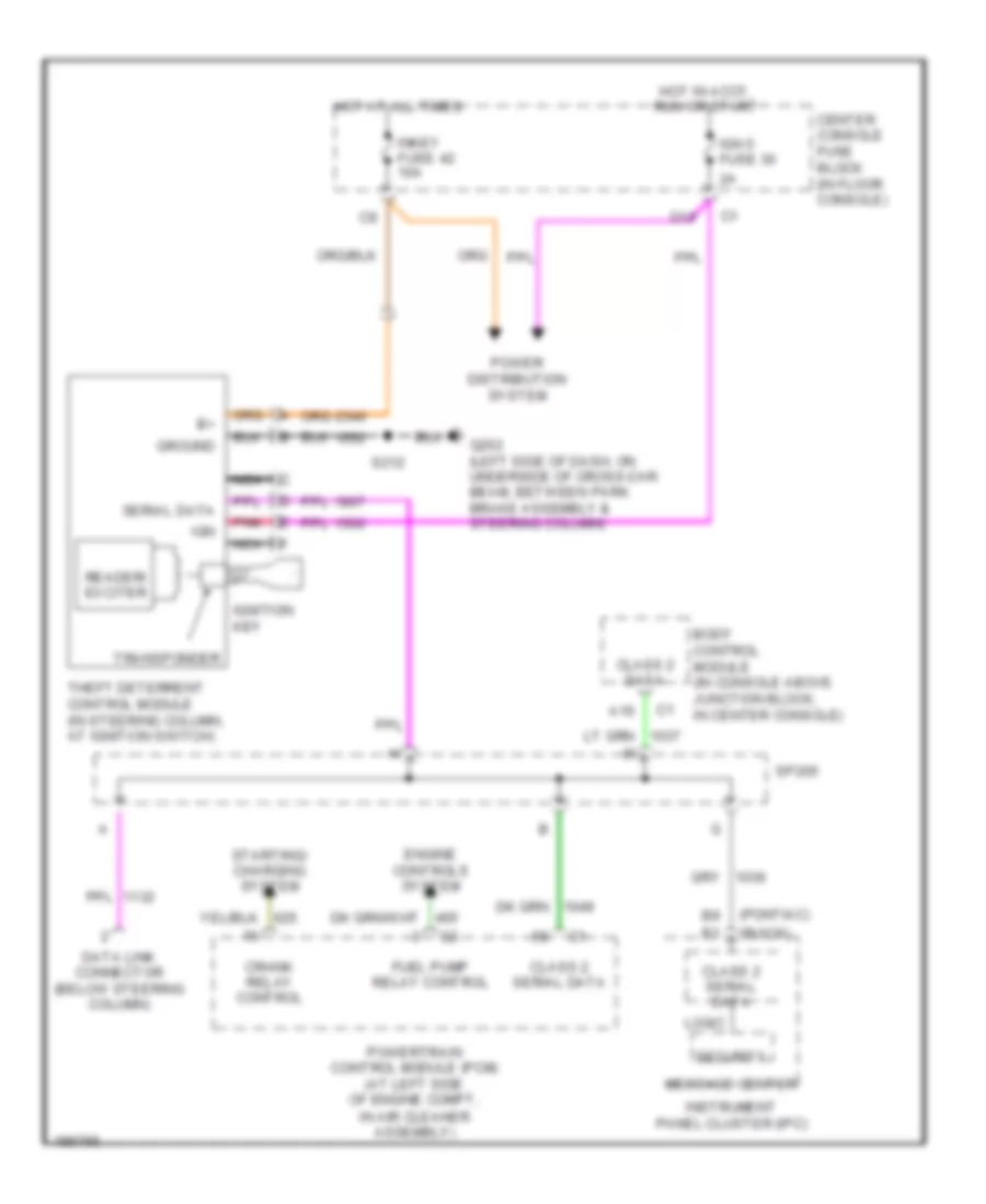
Pass-Key Wiring Diagram for Buick Rendezvous Ultra 2004
List of elements for Pass-Key Wiring Diagram for Buick Rendezvous Ultra 2004:
- (buick)
- (pontiac)
- A10
- Body control module (in console above junction block, in center console)
- Center console fuse block (in floor console)
- Class 2 data
- Class 2 serial data
- Crank relay control
- D10
- Data link connector (below steering column)
- Engine controls system
- Fuel pump relay control
- G202 (left side of dash, on underside of cross-car beam, between park brake assembly & steering column)
- Ground
- Hot at all times
- Hot in accy, run or start
- Ign
- Ign 0 fuse 30
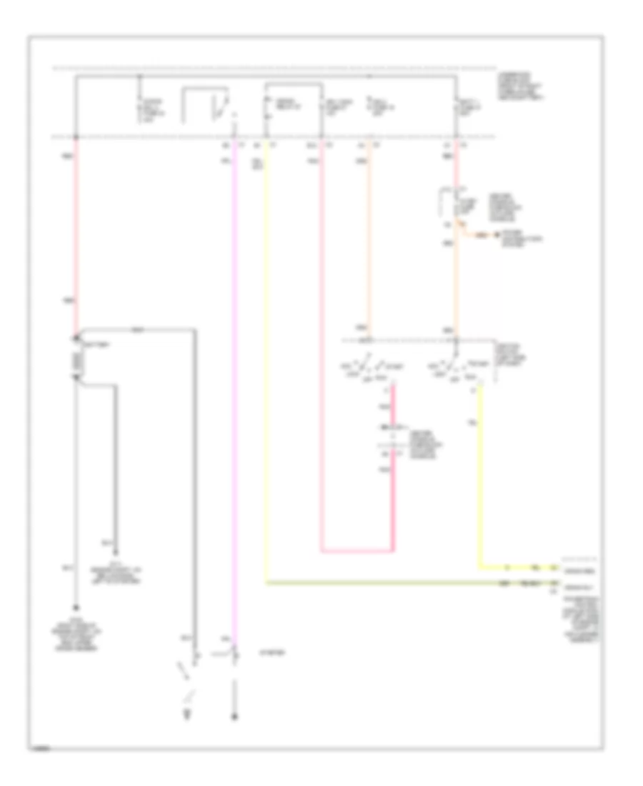
- Ignition key
- Inkey fuse 42 10a
- Instrument panel cluster (ipc)
- Logic
- Message center
- Nca
- Pnk
- Power distribution system
- Powertrain control module (pcm) (at left side of engine compt, in air cleaner assembly)
- Reader/ exciter
- S212
- Security
- Serial data
- Sp205
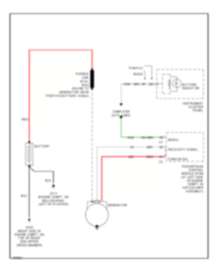
- Starting/ charging system
- Theft deterrent control module (in steering column, at ignition switch)
- Transponder
BODY CONTROL MODULES
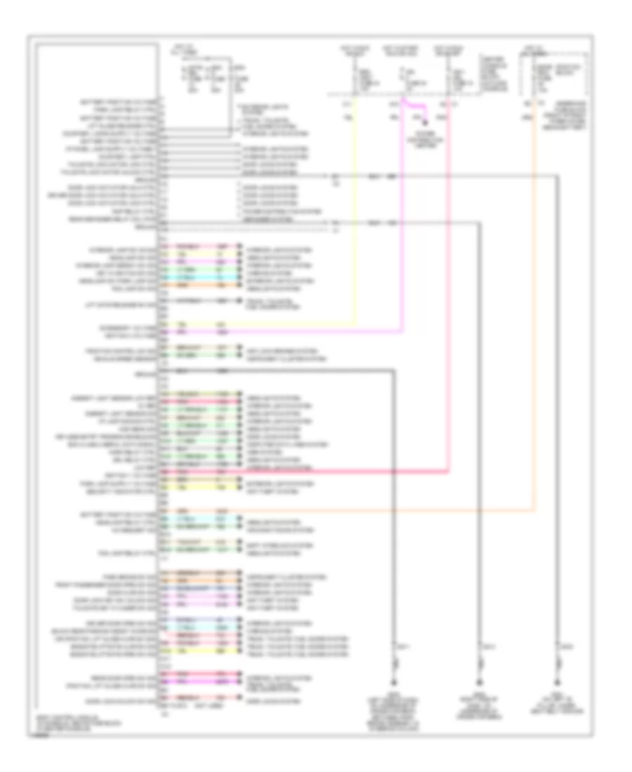
Body Control Modules Wiring Diagram for Buick Rendezvous Ultra 2004
List of elements for Body Control Modules Wiring Diagram for Buick Rendezvous Ultra 2004:
- (buick) rear parking assist chime sig
- (not used)
- (or (pontiac) lift glass ajar sw sig)
- (pontiac) (buick)
- (pontiac) lift glass ajar sw sig
- 5v ref
- A/c request sig
- A10
- A11
- A12
- Accessory voltage
- Air conditioning system
- Ambient light sensor low ref
- Ambient light sensor sig
- Anti-lock brakes system
- Anti-theft system
- B10
- B11
- B12
- B5 to b12
- Battery positive voltage
- Bcm class 2 serial data signal
- Bcm d fuse 25a
- Bcm l fuse 20a
- Bcm- accy fuse 44 10a
- Bcme bcm fuse 10a
- Body control module (in console, above fuse block, in center console)
- C1 a5
- C11
- Center console fuse block (in floor console)
- Computer data lines system
- Courtesy lamp ctrl
- D10
- Defogger system
- Door ajar sw sig
- Door lock actuator lock ctrl
- Door lock actuator unlk ctrl
- Door lock key sw unlock sig
- Door lock/unlock sw sig
- Door locks system
- Driver door lock actuator unlk ctrl
- Driver door open sw sig
- Drl relay ctrl
- Endgate/liftgate ajar sw sig
- Endgate/liftgate open sw sig
- Exterior lights system
- Fog lamp relay ctrl
- Fog lamp sw sig
- Front passenger door open sw sig
- G200 (right side of dash, on underside of cross-car beam)
- G202 (left side of dash, on underside of cross-car beam, between park brake assembly & steering column)
- G301 (on left "b" pillar, under seat belt anchor)
- Gate rel fuse 20a
- Ground
- Headlamp relay ctrl
- Headlamp sw park lamp sig
- Headlamp sw sig
- Headlights system
- High beam sig
- Horn relay ctrl
- Horn system
- Hot at all times
- Hot in run or acc
- Hot in run or start
- Hot in start, run or acc
- I/p lamp dimming ctrl
- Ign 1 mdl fuse 18 10a
- Ign fuse 30 2a
- Ignition 0 voltage
- Ignition 1 voltage
- Instrument cluster system
- Interior lamp defeat sw sig
- Interior lamp sw on sig
- Interior lights system
- Key in ignition sw sig
- Keyless entry program enable sig
- Lift gate release sw sig
- Lift glass release ctrl
- Low ref
- Park brake sw sig
- Park lamp relay ctrl
- Pnk
- Power distribution center
- Power distribution system
- Rap relay ctrl
- Rear defogger relay coil pwr
- Rear door open sw sig
- S211
- S214
- S333
- Security indicator ctrl
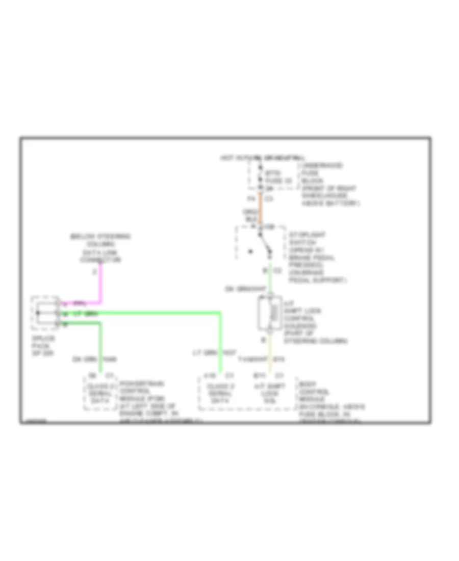
- Shift interlock system
- Tailgate key cylinder sw sig
- Tailgate lock motor lock ctrl
- Tailgate lock motor unlock ctrl
- Traction control sw sid
- Trunk, tailgate, fuel doors system
- Underhood fuse block (front of right wheelhouse, above battery)
- Vehicle speed sensor
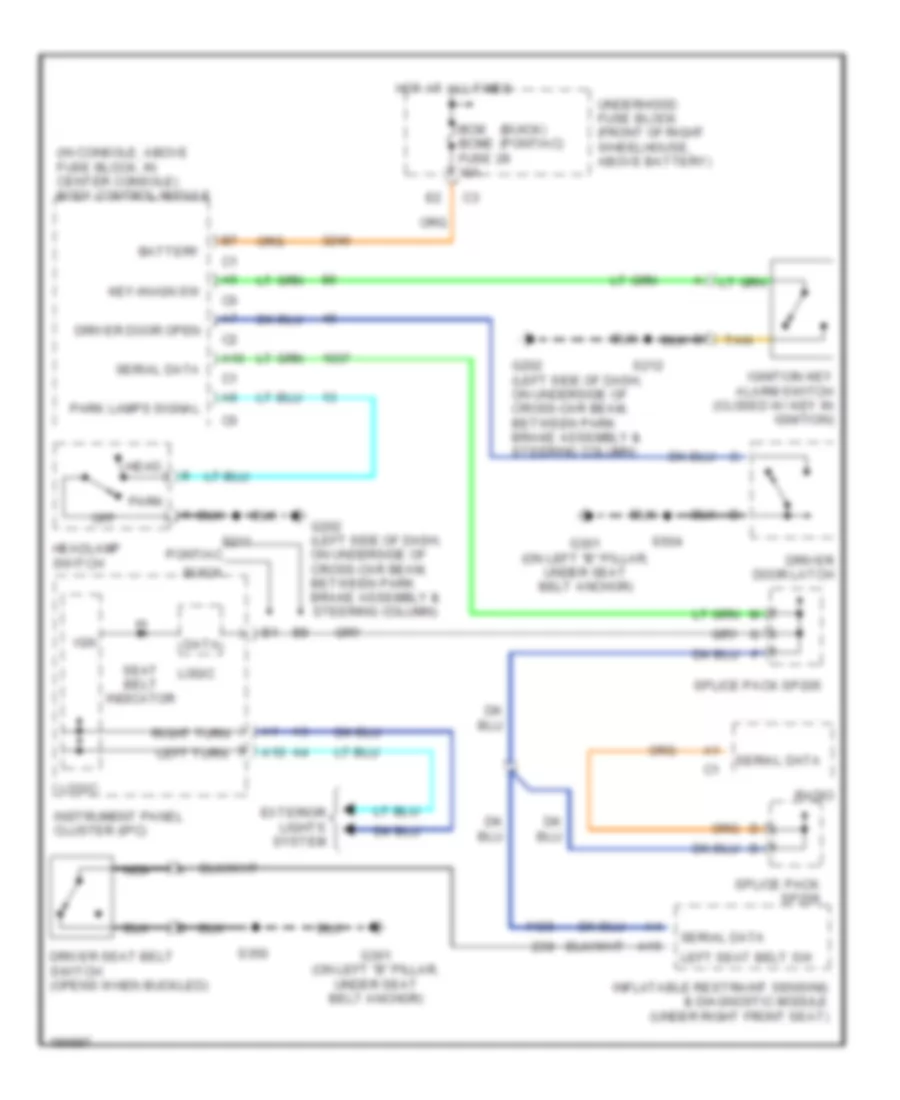
- Warning system
COMPUTER DATA LINES
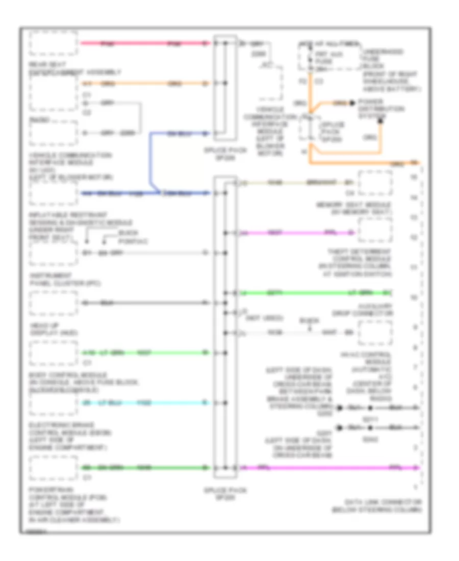
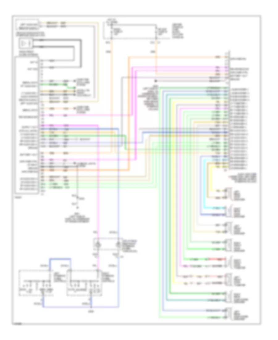
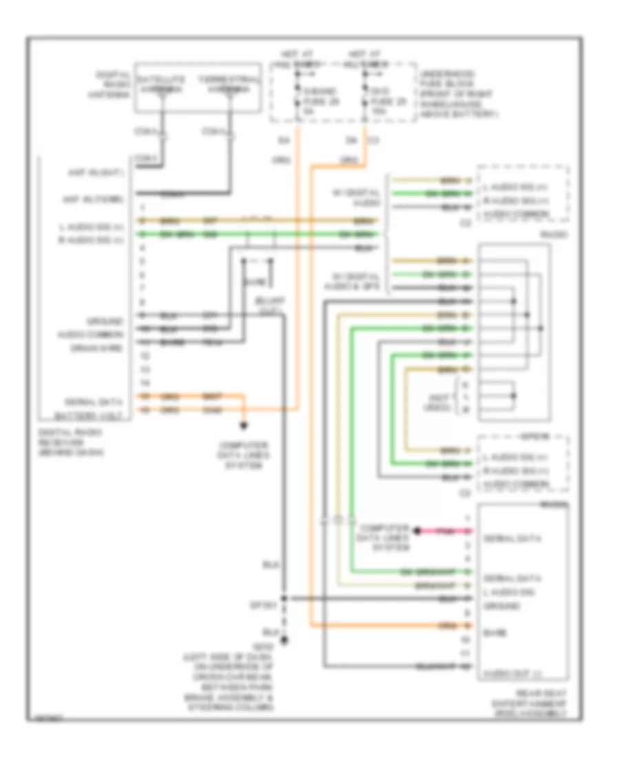
Computer Data Lines Wiring Diagram for Buick Rendezvous Ultra 2004
List of elements for Computer Data Lines Wiring Diagram for Buick Rendezvous Ultra 2004:
- (left side of dash, underside of cross-car beam, between park brake assembly & steering column) g202
- A10
- Auxiliary drop connector
- Body control module (in console, above fuse block, in center console)
- Buick
- D (not used)
- Data link connector (below steering column)
- Electronic brake control module (ebcm) (left side of engine compartment)
- Frt aux fuse 20a
- G201 (left side of dash, on underside of cross-car beam)
- Head up display (hud)
- Hot at all times
- Hvac control module (automatic a/c) (center of dash, below radio)
- Inflatable restraint sensing & diagnostic module (under right front seat)
- Instrument panel cluster (ipc)
- Memory seat module (w/ memory seat)
- Pnk
- Pontiac
- Power distribution system
- Powertrain control module (pcm) (at left side of engine compartment, in air cleaner assembly)
- Radio
- Rear seat entertainment assembly
- S211
- S242
- Splice pack sp205
- Splice pack sp206
- Splice pack sp250
- Theft deterrent control module (in steering column, at ignition switch)
- Underhood fuse block (front of right wheelhouse, above battery)
- Vehicle communication interface module (left of blower motor)
- Vehicle communication interface module (w/ ug1) (left of blower motor)
COOLING FAN
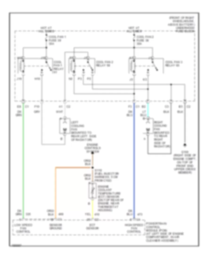
Cooling Fan Wiring Diagram for Buick Rendezvous Ultra 2004
List of elements for Cooling Fan Wiring Diagram for Buick Rendezvous Ultra 2004:
- (front of right wheelhouse, above battery) underhood fuse block
- Cool fan 1 fuse 39 30a
- Cool fan 1 relay
- Cool fan 2 fuse 38 30a
- Cool fan 2 relay 58
- Cool fan 3 relay 60
- Ect sensor
- Engine controls system
- Engine coolant temperature (ect) sensor (on top rear of engine, near thermostat housing)
- F10
- G100 (right side of engine compt, on top of front end upper cross member)
- H10
- H12
- High speed fan control
- Hot at all times
- J10
- J12
- Left cooling fan (mounted to rear left side of radiator)
- Low speed fan control
- Powertrain control module (pcm) (at left side of engine compartment, in air cleaner assembly)
- Right cooling fan (mounted to rear right side of radiator)
- S110 (fuel injector harness, 5 cm from c102)
- Sensor ground
CRUISE CONTROL
3.4L VIN E
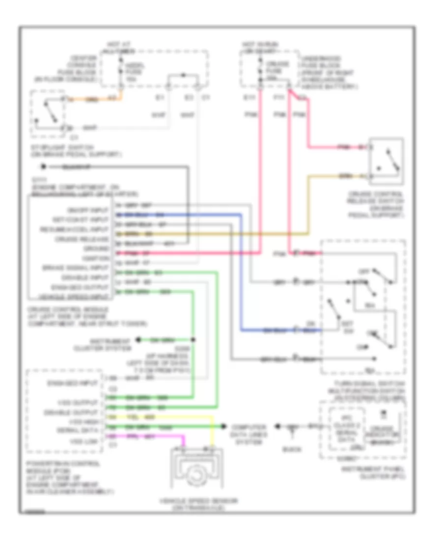
3.4L VIN E, Cruise Control Wiring Diagram for Buick Rendezvous Ultra 2004
List of elements for 3.4L VIN E, Cruise Control Wiring Diagram for Buick Rendezvous Ultra 2004:
- All times
- Brake signal input
- Buick
- Center console fuse block (in floor console)
- Computer data lines system
- Cruise control module (at left side of engine compartment, near strut tower)
- Cruise control release switch (on brake pedal support)
- Cruise fuse 10a
- Cruise indicator (buick)
- Cruise release
- Disable input
- Disable output
- E11
- Engaged input
- Engaged output
- F11
- G111 (engine compartment, on bellhousing, left of starter)
- Ground
- Hot at
- Hot in run or start
- Hzdfl fuse 15a
- Ign
- Ignition
- Instrument cluster system
- Instrument panel cluster (ipc)
- Ipc class 2 serial data
- Logic
- Off
- On/off input
- Pnk
- Powertrain control module (pcm) (at left side of engine compartment, in air cleaner assembly)
- R/a
- Resume/accel input
- S209 (i/p harness, left side of dash, 7.5 cm from p101)
- Serial data
- Set sw
- Set/coast input
- Stoplight switch (on brake pedal support)
- Turn signal switch/ multifunction switch (in steering column)
- Underhood fuse block (front of right wheelhouse, above battery)
- Vehicle speed input
- Vehicle speed sensor (on transaxle)
- Vss high
- Vss low
- Vss output
3.6L VIN 7
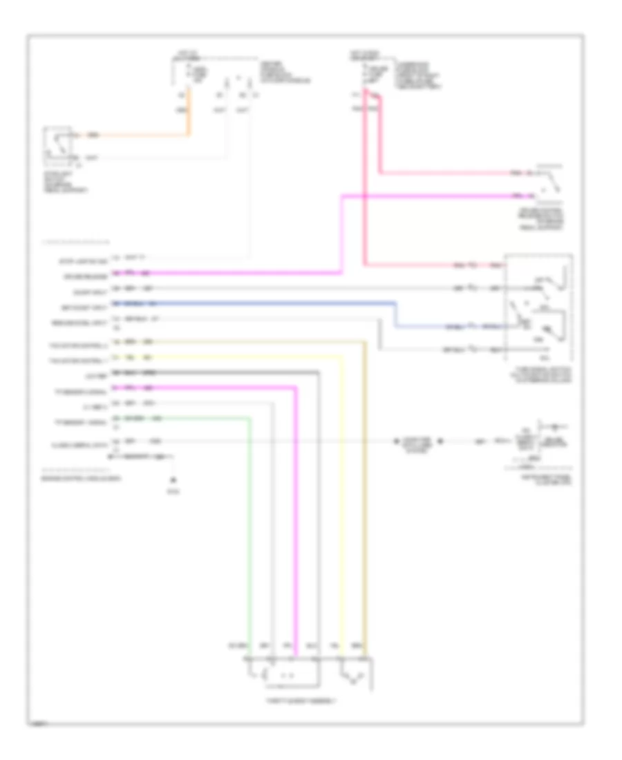
3.6L VIN 7, Cruise Control Wiring Diagram for Buick Rendezvous Ultra 2004
List of elements for 3.6L VIN 7, Cruise Control Wiring Diagram for Buick Rendezvous Ultra 2004:
- 5 v ref c
- All times
- Center console fuse block (in floor console)
- Class 2 serial data
- Computer data lines system
- Cruise control release switch (on brake pedal support)
- Cruise fuse 10a
- Cruise indicator
- Cruise release
- Engine control module (ecm)
- F11
- G133
- Hot at
- Hot in run or start
- Hzdfl fuse 15a
- Ign
- Instrument panel cluster (ipc)
- Ipc class 2 serial data
- Logic
- Low ref
- Off
- On/off input
- Pnk
- R/a
- Resume/accel input
- Set sw
- Set/coast input
- Stop lamp sw sig
- Stoplight switch (on brake pedal support)
- Tac motor control 1
- Tac motor control 2
- Throttle body assembly
- Tp sensor 1 signal
- Tp sensor 2 signal
- Turn signal switch/ multifunction switch (in steering column)
- Underhood fuse block (front of right wheelhouse, above battery)
DEFOGGERS
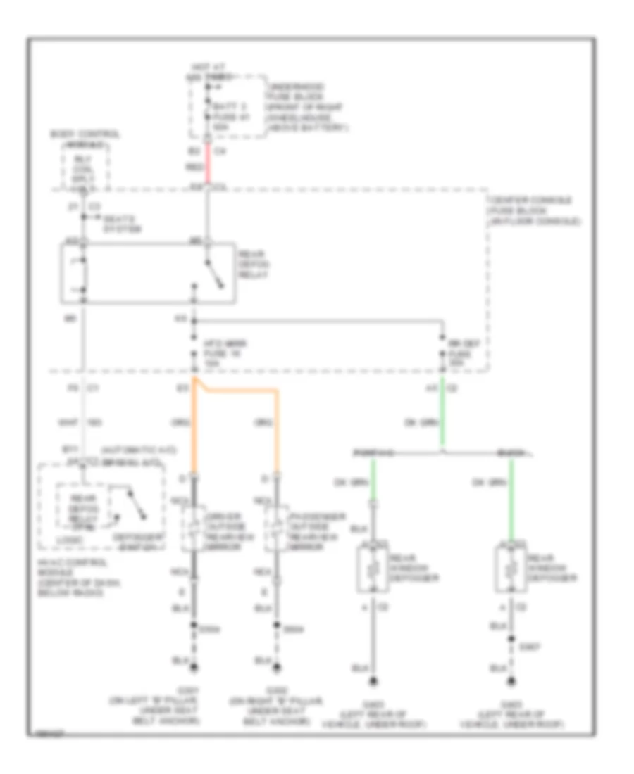
Defoggers Wiring Diagram for Buick Rendezvous Ultra 2004
List of elements for Defoggers Wiring Diagram for Buick Rendezvous Ultra 2004:
- (automatic a/c)
- (manual a/c)
- B11
- Batt 3 fuse 41 60a
- Body control module
- Buick
- C1 a
- C1 a4
- C1 f6
- C2 a
- C2 a5
- Center console fuse block (in floor console)
- Defogger switch
- Driver outside rearview mirror
- G301 (on left "b" pillar, under seat belt anchor)
- G302 (on right "b" pillar, under seat belt anchor)
- G403 (left rear of vehicle, under roof)
- Hot at all times
- Htd mirr fuse 16 10a
- Hvac control module (center of dash, below radio)
- Logic
- Nca
- Passenger outside rearview mirror
- Pontiac
- Rear defog relay
- Rear defog relay ctrl
- Rear window defogger
- Red
- Rly coil sply volt
- Rr def fuse 30a
- S504
- S604
- S907
- Seats system
- Underhood fuse block (front of right wheelhouse, above battery)
ELECTRONIC SUSPENSION
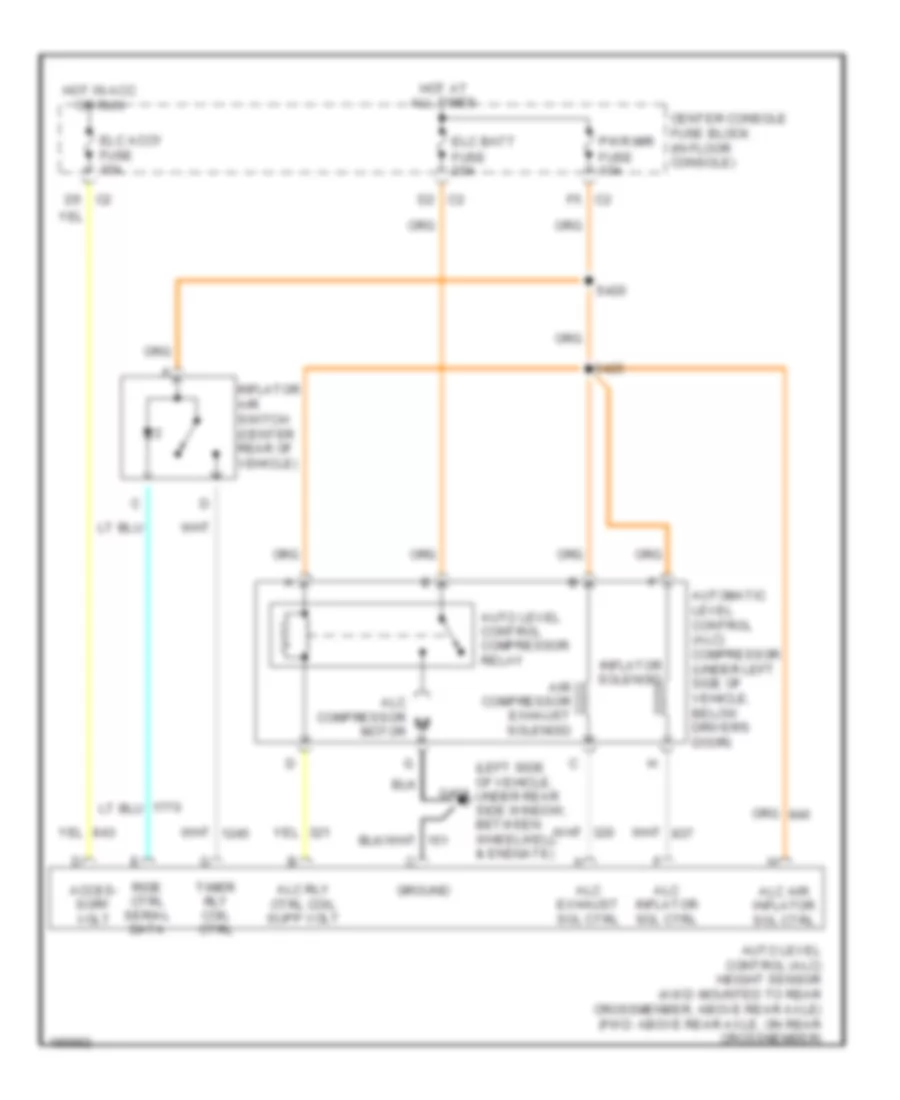
Electronic Suspension Wiring Diagram for Buick Rendezvous Ultra 2004
List of elements for Electronic Suspension Wiring Diagram for Buick Rendezvous Ultra 2004:
- (left side of vehicle, g401 under rear side window, between wheelwell & endgate)
- Acces- sory volt
- Air compressor exhaust solenoid
- Alc air inflator sol ctrl
- Alc compressor motor
- Alc exhaust sol ctrl
- Alc inflator sol ctrl
- Alc rly ctrl coil supp volt
- Auto level control (alc) height sensor (awd: mounted to rear crossmenber, above rear axle) (fwd: above rear axle, on rear crossmember)
- Auto level control compressor relay
- Automatic level control (alc) compressor (under left side of vehicle, below driver's door)
- Center console fuse block (in floor console)
- Elc accy fuse 10a
- Elc batt fuse 20a
- Ground
- Hot at all times
- Hot in acc or run
- Inflator air switch (center rear of vehicle)
- Inflator solenoid
- Pwr mir fuse 10a
- Ride ctrl serial data
- S420
- S425
- Timer rly coil ctrl
ENGINE PERFORMANCE
3.4L VIN E
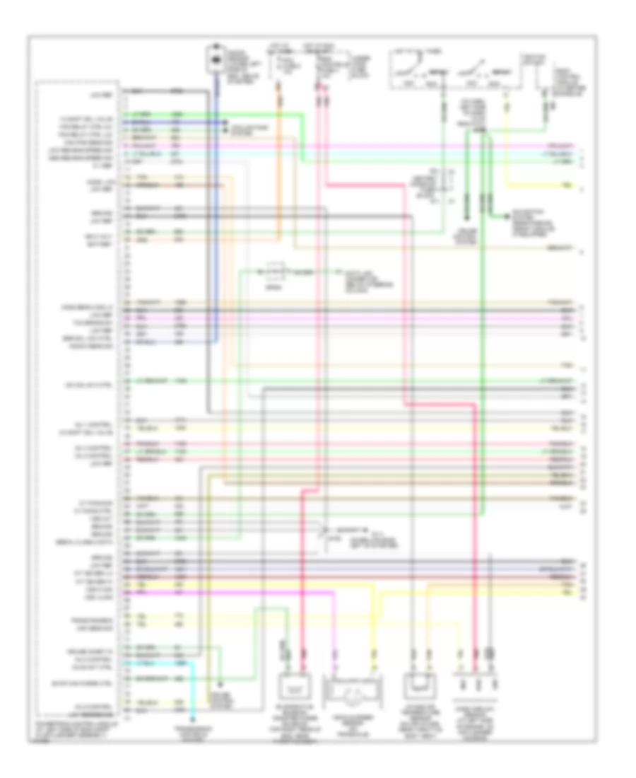
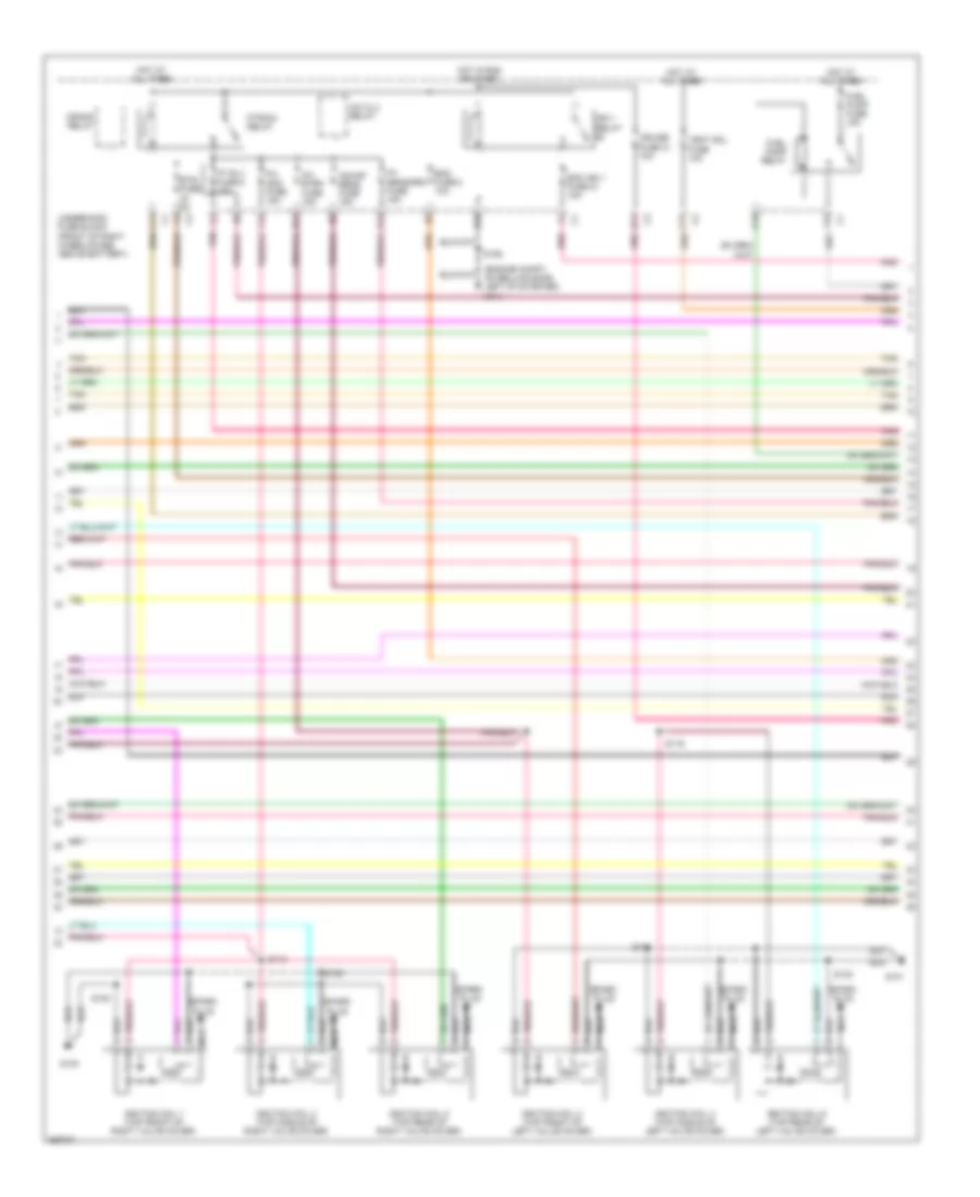
3.4L VIN E, Engine Performance Wiring Diagram (1 of 4) for Buick Rendezvous Ultra 2004
List of elements for 3.4L VIN E, Engine Performance Wiring Diagram (1 of 4) for Buick Rendezvous Ultra 2004:
- (i/p harn, left side of dash 7.5 cm from p101) s209
- (on bellhousing left of starter)
- 1-2 shift sol valve
- 2-3 shift sol valve
- 5 v ref
- A/t iss sen hi
- A/t iss sen lo
- Acc
- Axle act ctrl
- Battery
- Body control module (in center console)
- Cam pos sens sig
- Center console fuse block
- Cooling fans system
- Cruise control system
- Cruise inhibit in
- D11
- Data link connector (below steering column)
- E11
- Egr sol low ctrl
- Eng controls fuse 4 10a
- Evap can purge ctrl
- Evaporative emission canister purge solenoid (top right rear of eng, near throttle body)
- Fan relay ctrl (hi)
- Fan relay ctrl (lo)
- G111
- Gnd
- Ground
- Ho2s sens 2 sig lo
- Ho2s1 low
- Hot at all times
- Hot at run or start
- Iac coil b hi ctrl
- Ic timing ctrl
- Ic timing sig
- Ign 0 volt
- Ignition switch
- Inj 1 control
- Inj 2 control
- Inj 3 control
- Inj 5 control
- Inj 6 control
- Intake air temperature sensor (on air intake, near throttle body assy)
- Knock sens sig
- Knock sensor (lower left side of eng, above starter)
- Lock
- Low ref
- Low reference
- Low res eng speed sig
- Maf
- Maf sens sig
- Mass airflow sensor (at left side of engine, on air cleaner housing)
- Med res eng speed sig
- Navigation system (rear parking assist module) (if equipped)
- Pcm fuse 5 10a
- Pnk
- Powertrain control module (at left side of eng compt in air cleaner assembly)
- Pwr
- Run
- S106
- Serial class 2 data
- Sp205
- Start
- Tan
- Tcc brake sw
- Trans range b
- Transmission controls system
- Under- hood fuse block
- Vehicle speed sensor (on transaxle)
- Vss hi sig
- Vss lo sig
- Vss out
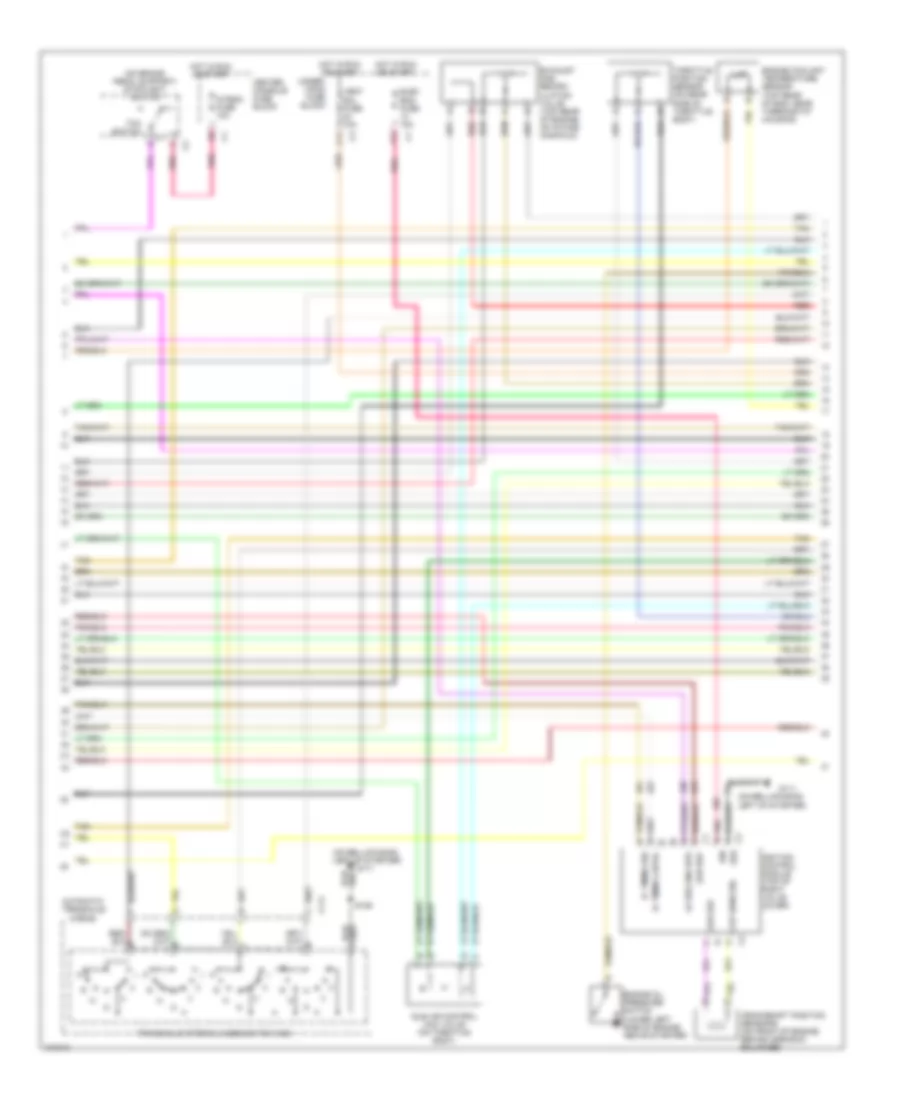
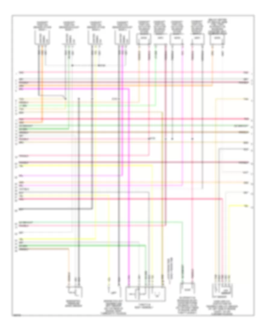
3.4L VIN E, Engine Performance Wiring Diagram (2 of 4) for Buick Rendezvous Ultra 2004
List of elements for 3.4L VIN E, Engine Performance Wiring Diagram (2 of 4) for Buick Rendezvous Ultra 2004:
- (4t65-e)
- (buick) a11
- (engine compt, on bellhousing left of starter)
- (pontiac) a2 mil ind (chk eng)
- 1-2 shift solenoid
- 2-3 shift solenoid
- 5v ref
- A/t fluid pressure manual valve position switch
- A/t input shaft speed sensor
- Automatic transaxle
- Automatic transaxle fluid temper- ature sensor
- B10
- C111
- C12
- Camshaft position sensor (top front of eng)
- Center console fuse block
- Crankshaft position sensor sensor a (on lower right side of engine)
- D12
- F12
- Fuel pump & sender assembly
- Fuel pump fuse 1 15a
- Fuel pump relay
- Fuel tank
- Fuel tank pressure sensor
- G111
- G301 (left "b" pillar, under seat belt anchor)
- Hot at all times
- Hot in run or start
- Instrument cluster
- Manifold absolute pressure sensor (top front of eng)
- Map
- Nca
- Pnk
- Pressure control solenoid
- Red
- Rtn
- S106
- S110 (fuel inj harn, 5 cm from c102)
- S329
- Tan
- Tcc pwm solenoid
- Trans sol fuse 10a
- Underhood fuse block
- V10
- V12
- W10
- W12
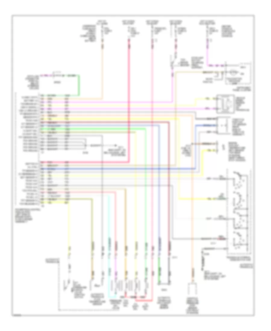
3.4L VIN E, Engine Performance Wiring Diagram (3 of 4) for Buick Rendezvous Ultra 2004
List of elements for 3.4L VIN E, Engine Performance Wiring Diagram (3 of 4) for Buick Rendezvous Ultra 2004:
- (4t65-e)
- (on bellhousing, left of starter)
- (on brake pedal support) stoplight switch
- Automatic transaxle
- C11
- C111
- C3 grd
- Center console fuse block
- Ckp sens sig
- Crankshaft position sensor b (on front of engine, behind harmonic balancer)
- Elec eng fuse 15a
- Engine coolant temperature sensor (top rear of eng, near thermostat housing)
- Engine oil pressure switch (lower left side of engine, above starter)
- Exhaust gas recirc- ulation valve (top rear of engine, on intake manifold)
- F12
- G111
- Hot in run or start
- Ic timing cntrl
- Ic timing sig
- Idle air control (iac) valve (on throttle body)
- Ign
- Ignition control module (top of right valve cover)
- Intemm fuse 10a
- Lo res eng spd
- Low ref
- Pnk
- Pnk b
- Red
- S106
- Tan
- Tcc switch
- Throttle position sensor (on rear side of throttle body)
- Transaxle internal mode switch (ims)
- Under- hood fuse block
- Vent sol fuse 10a
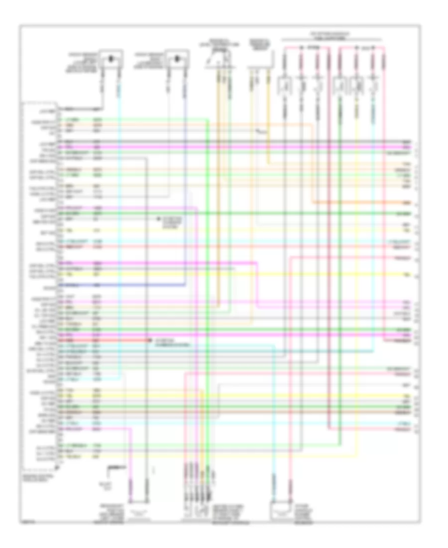
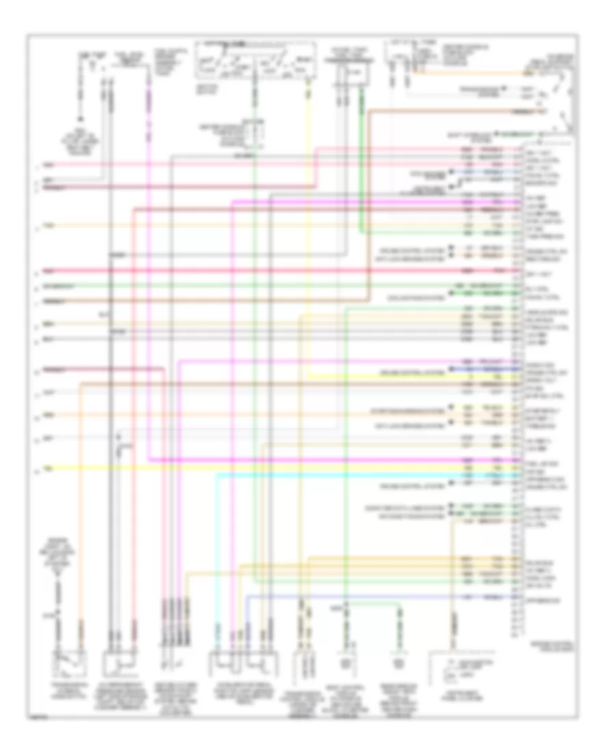
3.4L VIN E, Engine Performance Wiring Diagram (4 of 4) for Buick Rendezvous Ultra 2004
List of elements for 3.4L VIN E, Engine Performance Wiring Diagram (4 of 4) for Buick Rendezvous Ultra 2004:
- (engine compt, on bellhousing, above starter)
- (fuel inj harn, 39 cm from c102)
- 12 volt ref
- 5 v ref
- 5v ref a
- 5v ref b
- A/c comp rly ctrl
- A/c refrig press sig
- A/c refrigerant pressure sensor (below air cleaner)
- Air conditioning system
- Crank rly ctrl
- Crank volt
- Cruise control system
- Cruise engage sig
- E12
- Ect sens sig
- Egr sol hi ctrl
- Egr valve pos sig
- Evap can vent sol ctrl
- Evaporative emission canister vent solenoid (below center of vehicle, near fuel tank)
- Fuel inj fuse 11 15a
- Fuel injectors
- Fuel level sens sig
- Fuel pump relay ctrl
- Fuel tnk press sens sig
- G117
- Generator turn on sig
- Heated oxygen sensor 1 (on exhaust manifold, right side of eng)
- Heated oxygen sensor 2 (on exhaust system, behind catalytic converter)
- Ho2s 1 heater lo ctrl
- Ho2s sens 1 sig hi
- Ho2s sens sig 2 hi
- Hot in run or start
- Iac coil a hi ctrl
- Iac coil a lo ctrl
- Iac coil b lo ctrl
- Iat sens sig
- Ign 1 voltage
- Ign1 main fuse 27 10a
- Inj 4 control
- Low ref
- Map sens sig
- Mil ctrl
- O2 sensors fuse 10 15a
- Oil pressure sw sig
- Pc sol val hi ctrl
- Pc sol val lo ctrl
- Pnk
- Powertrain control module (left side of eng compt, (in air cleaner assembly)
- Red
- S105
- S109
- Starting/ charging system
- Tan
- Tcc pwm sol ctrl
- Tcc release sw sig
- Tft sens sig
- Tps sens sig
- Trs sig a
- Trs sig c
- Trs sig p
- Under- hood fuse block
3.6L VIN 7
3.6L VIN 7, Engine Performance Wiring Diagram (1 of 4) for Buick Rendezvous Ultra 2004
List of elements for 3.6L VIN 7, Engine Performance Wiring Diagram (1 of 4) for Buick Rendezvous Ultra 2004:
- (on intake manifold) fuel injectors
- +5v
- +5v ref
- Bare
- Baro sig
- Ckp sens ref
- Ckp sens sig
- Cmp sig
- Cmp sol ctrl
- Crankshaft position (ckp) sensor (left lower rear of engine)
- Ect sig
- Engine control module (ecm)
- Engine oil level/temperature sensor
- Engine oil pressure sensor
- Evap sol ctrl
- Gen fdc sig
- Gen to sig
- Gnd
- Heated oxygen sensor (ho2s 1) (at right side of engine, on exhaust manifold)
- Ho2s hi sig
- Ho2s lo ctrl
- Ho2s pmp ct
- Ign 1 sig
- Ign 2 ctrl
- Ign 3 ctrl
- Ign 4 sig
- Ign 5 ctrl
- Ign 6 ctrl
- Imrc sol ctrl
- Inj 1 ctrl
- Inj 2 ctrl
- Inj 3 ctrl
- Inj 4 ctrl
- Inj 5 ctrl
- Inj 6 ctrl
- Intake manifold runner control solenoid
- Knock sensor bank 1 (lower right side of engine)
- Knock sensor bank 2 (lower left side of engine, above starter) nca
- Ks sig
- Low ref
- Nca
- Oil lev sig
- Oil pres sig
- Oil tmp sig
- Red
- S121
- S122
- S127
- Starting/ charging system
- Tac mtr ctrl
- Tan
- Tp sig
- Tp2 sig
3.6L VIN 7, Engine Performance Wiring Diagram (2 of 4) for Buick Rendezvous Ultra 2004
List of elements for 3.6L VIN 7, Engine Performance Wiring Diagram (2 of 4) for Buick Rendezvous Ultra 2004:
- (engine compt, on bellhousing, left of starter) g111
- A/c clu relay
- B10
- Btsi fuse 2a
- C11
- C12
- Crank relay
- Cruise fuse 31 10a
- D12
- E11
- E12
- Ecm fuse 5 10a
- Ecm ign 1 fuse 21 15a
- F12
- Fuel pump fuse 15a
- Fuel pump relay
- G130
- G131
- Hot at all times
- Hot in run or start
- Ign 1 relay
- Ignition coil 1 (top front of right valve cover)
- Ignition coil 2 (top front of left valve cover)
- Ignition coil 3 (top middle of right valve cover)
- Ignition coil 4 (top middle of left valve cover)
- Ignition coil 5 (top rear of right valve cover)
- Ignition coil 6 (top rear of left valve cover)
- Inj even fuse 15a
- Inj odd fuse 15a
- Nca
- O2/maf sens fuse 15a
- Pnk
- Pt rly fuse 6 15a
- Pt sensors fuse 15a
- Ptrain relay
- S106
- S112
- S119
- S130
- S131
- S132
- S133
- Spark plug
- Tan
- Underhood fuse block (front of right wheelhouse, above battery)
- Vent sol fuse 10a
3.6L VIN 7, Engine Performance Wiring Diagram (3 of 4) for Buick Rendezvous Ultra 2004
List of elements for 3.6L VIN 7, Engine Performance Wiring Diagram (3 of 4) for Buick Rendezvous Ultra 2004:
- (below center of vehicle, near fuel tank) evaporative emissions canister vent solenoid valve
- +5v
- Barometric pressure (baro) sensor
- Camshaft position actuator solenoid exhaust bank 1
- Camshaft position actuator solenoid exhaust bank 2
- Camshaft position actuator solenoid intake bank 1
- Camshaft position actuator solenoid intake bank 2
- Camshaft position sensor exhaust bank 1
- Camshaft position sensor exhaust bank 2
- Camshaft position sensor intake bank 1
- Camshaft position sensor intake bank 2
- Early production
- Engine coolant temperature (ect) sensor (on top rear of engine, near thermostat housing)
- Evaporative emissions (evap) canister purge solenoid valve (on top right rear of engine, near throttle body)
- Iat sensor
- Late production
- Low ref
- Maf sensor
- Mass airflow (maf)/intake air temperature (iat) sensor (at left side of engine compt, on air cleaner housing)
- Pnk
- S120
- S126
- S128
- Signal
- Tan
- Throttle body assembly
3.6L VIN 7, Engine Performance Wiring Diagram (4 of 4) for Buick Rendezvous Ultra 2004
List of elements for 3.6L VIN 7, Engine Performance Wiring Diagram (4 of 4) for Buick Rendezvous Ultra 2004:
- (engine compt, on bellhousing, left of starter) g111
- (in fuel tank) fuel tank pressure sensor
- (on brake pedal support) stoplamp switch
- +5v ref
- +5v ref a
- +5v ref c
- A/c ref pres
- A/c refrigerant pressure sensor (left side of engine compt, below air cleaner assembly)
- A11
- Acc
- Accelerator pedal position (app) sensor (above accelerator pedal)
- Air conditioning system
- Anti-lock brakes system
- App sens 2 sig
- App sens sig
- Battery +
- Body control module (in console, above fuse block, in center console)
- Center console fuse block (in floor console)
- Class 2 data
- Clu rly ctrl
- Computer data lines system
- Cooling fans system
- Crank volt
- Cruise control system
- Cruise ctrl sw
- D11
- E11
- Eng spd sig
- Engine control module (ecm)
- Evap sol ctrl
- Fan rly ctrl
- Fuel lev sig
- Fuel level sensor
- Fuel pump
- Fuel pump & sender assembly (in fuel tank)
- G301 (on left "b" pillar, under seat belt anchor)
- Gmlan bus
- Heated oxygen sensor (ho2s 2) (on exhaust system, behind catalytic converter)
- Ho2s hi sig
- Ho2s lo ctrl
- Ho2s lo sig
- Hot at all times
- Hzdfl fuse 40 15a
- Iat sig
- Ign
- Ign 1 volt
- Ign volts
- Ignition switch
- Instrument cluster system
- Instrument panel cluster
- Lan bus +
- Lan bus -
- Lock
- Logic
- Low ref
- Maf sig
- Malfunction ind lamp
- Mil ctrl
- Nca
- Off
- P/n sig
- Pnk
- Ptrain rly ctrl
- Rear parking assist (rpa) module (behind front center dash console)
- Req torq sig
- Rly ctrl
- Run
- S106
- S108
- S125
- S209
- S329
- Shift interlock system
- Spd sig
- Start
- Starter rly
- Starting/charging system
- Stop lamp sw
- Tan
- Tank pres sig
- Torque sig
- Transmission control module (inside air cleaner assembly)
- Transmission internal mode switch
- Transmissions system
- Vehicle spd sig
EXTERIOR LIGHTS
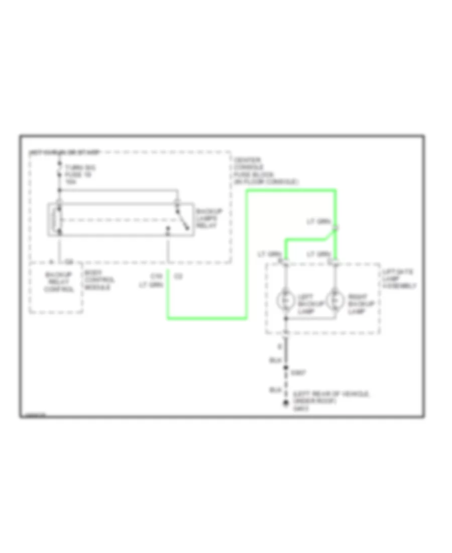
Back-up Lamps Wiring Diagram for Buick Rendezvous Ultra 2004
List of elements for Back-up Lamps Wiring Diagram for Buick Rendezvous Ultra 2004:
- (left rear of vehicle, under roof) g403
- Backup lamps relay
- Backup relay control
- Body control module
- C10
- Center console fuse block (in floor console)
- Hot in run or start
- Left backup lamp
- Liftgate lamp assembly
- Right backup lamp
- S907
- Turn sig fuse 19 10a
Exterior Lamps Wiring Diagram for Buick Rendezvous Ultra 2004
List of elements for Exterior Lamps Wiring Diagram for Buick Rendezvous Ultra 2004:
- (4 bulbs)
- (forward lamp harness, left front of vehicle, 5 cm from right foglamp breakout) s101
- (forward lamp harness, right front of vehicle, 5 cm from right foglamp breakout)
- A right front marker lamp b
- A10
- A11
- B5 pnk
- Body control module (in console, above fuse block, in center console)
- C8 c3
- Center console fuse block (in floor console)
- Center high mounted stop lamp (chmsl)
- D10
- E10
- E11
- G100 (right side of engine compt, on top of front end upper cross member)
- G101 (left side of engine compt, right of left headlamp, on front upper crossmember)
- G200 (right side of dash, on underside of cross-car beam)
- G201 (left side of dash, on underside of cross-car beam)
- G202 (left side of dash, on underside of cross-car beam, between park brake assembly & steering column)
- G401 (left side of vehicle, under rear side window, between wheelwell & endgate)
- G402 (right rear of vehicle, under roof)
- G403 (left rear of vehicle, under roof)
- Ground
- Ground distri- bution system
- Hazard sw sig
- Hazard switch
- Head
- Head up display (hud)
- Headlamp switch
- Hot at all times
- Hot in run or start
- Hzd fl fuse 40 15a
- Instrument panel cluster (ipc)
- Interior lights system
- Left front marker lamp
- Left front park/ turn signal lamp
- Left rear marker lamp
- Left turn ind
- Liftgate lamp assembly
- Logic
- Lt rr s/t volt
- Lt trn sig volt
- Lt turn sig
- Lt turn sig volt
- Off
- Park
- Park lamps
- Park lmp ctrl
- Park lmp sig
- Park lmp volt
- Park lps fuse 20 15a
- Park lps relay 54
- Pnk
- Power distribution system
- Right front park/ turn signal lamp
- Right rear marker lamp
- Right rear park/ stop/ turn signal lamp
- Right turn ind
- Rr aux fuse 14 20a
- Rt rr s/t volt
- Rt trn sig volt
- Rt turn sig
- Rt turn sig volt
- S102
- S126
- S127
- S211
- S212
- S213
- S242
- S301
- S305 (w/ auto air level control)
- S400
- S907
- Sp250
- Sp409
- Stop lamp sw sig
- Stoplight switch (on brake pedal support)
- Tan
- Turn sig fuse 19 10a
- Turn sig switch
- Turn signal/ multifunction switch (in steering column)
- Turn signal/hazard flasher module
- Underhood fuse block (front of right wheelhouse, above battery)
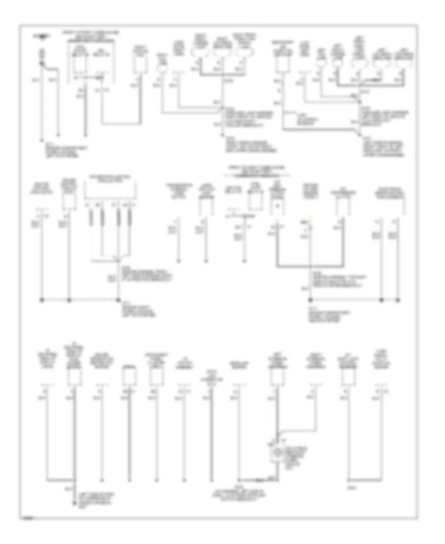
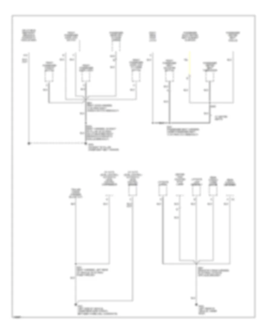
GROUND DISTRIBUTION
Ground Distribution Wiring Diagram (1 of 4) for Buick Rendezvous Ultra 2004
List of elements for Ground Distribution Wiring Diagram (1 of 4) for Buick Rendezvous Ultra 2004:
- (front of right wheelhouse, above battery) underhood fuse block
- (high note) right horn
- (if equipped) head up display (hud)
- (if equipped) head up display (hud) dimmer switch
- (left side of dash, on underside of cross-car beam) g201
- (low note) left horn
- A/c com- pressor clutch diode
- A/c compressor clutch
- A/t shift lock control solenoid
- B10
- Battery
- Cool fan sp relay 59
- Cruise control module (ccm)
- D nca
- Data link connector (dlc)
- Driver information center (dic) switch
- Drl relay 53
- Electronic brake control module (ebcm)
- Fuel pump relay 51
- G100 (right side of engine compt, on top of front end upper cross member)
- G101 (left side of engine compt, right of left headlamp, on front upper crossmember)
- G111 (engine compartment, on bellhousing, left of starter)
- G111 (engine compt, on bellhousing, left of starter)
- G117 (engine compartment, on bell housing, above starter)
- Headlamp switch
- Heated oxygen sensor (ho2s) 2
- I/p switch assembly
- Ignition control module (icm)
- Ignition relay 60
- Inflatable restraint steering wheel module coil
- Instrumemt panel cluster (ipc)
- Left fog lamp
- Left front marker lamp
- Left front park/ turn signal lamp
- Left high beam headlamp
- Left low beam headlamp
- Left steering wheel controls
- M11
- Mass air flow (maf) sensor
- Powertrain control module (pcm)
- Radio
- Right cooling fan
- Right fog lamp
- Right front marker lamp
- Right front park/turn signal lamp
- Right low beam headlamp
- Right steering wheel controls
- S105 (engine harness, top right side of radiator, 6 cm from starter breakout)
- S106 (engine harness, front left side of engine compt, 47 cm from pcm breakout)
- S123 (forward lamp harness, right front of vehicle, 5 cm from right foglamp breakout)
- S126
- S127
- S242 (i/p harness, left side of dash, 24 cm from stoplamp switch breakout)
- S243
- Secondary air injection (air) pump
- Transmission internal mode switch
- Turn signal/ multi- function switch
- Ulev california emission
- W10
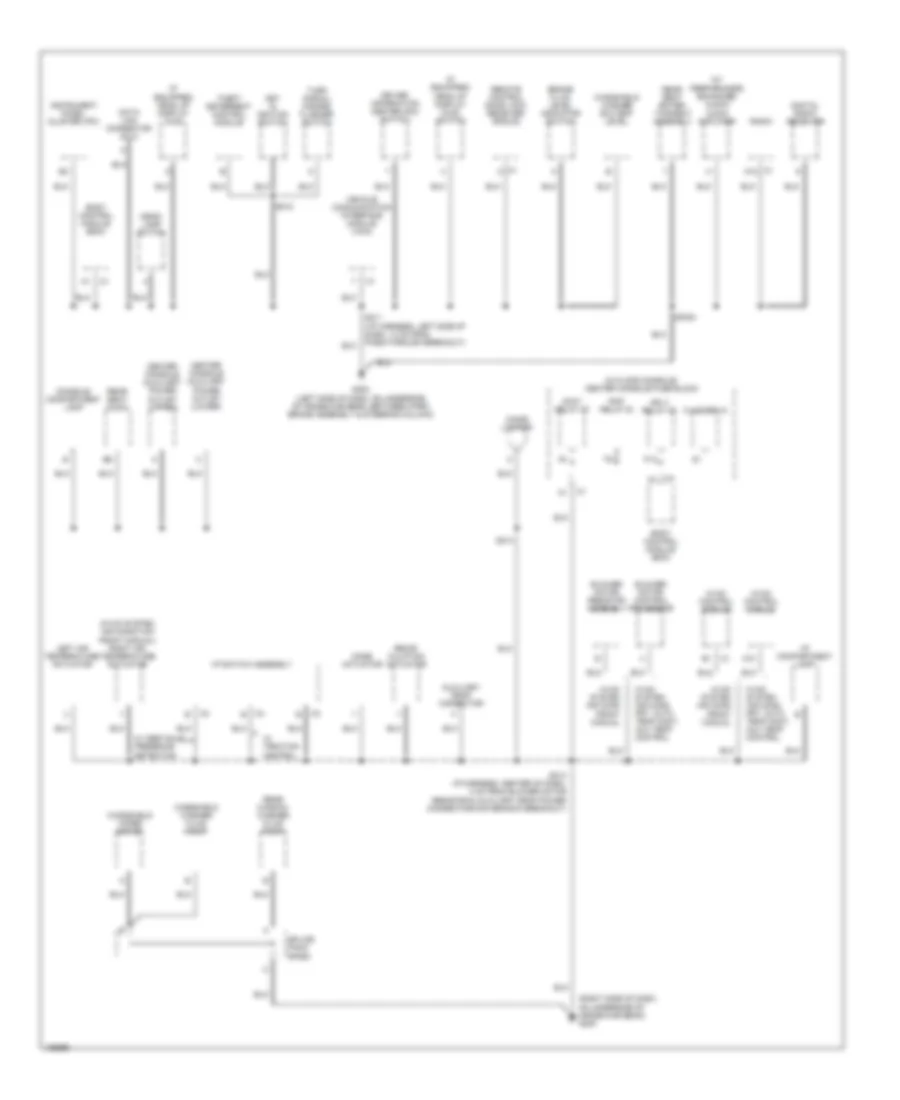
Ground Distribution Wiring Diagram (2 of 4) for Buick Rendezvous Ultra 2004
List of elements for Ground Distribution Wiring Diagram (2 of 4) for Buick Rendezvous Ultra 2004:
- (hvac system air condition front manual) right air temperature actuator
- (if equipped) head up display (hud)
- (if equipped) head up display (hud) switch
- (in floor console) center console fuse block
- (right side of dash, on underside of cross-car beam) g200
- (w/ performance enhanced audio) audio amplifier
- A10
- Accy relay 27
- Auxiliary drop connector
- Blower motor control processor
- Blower motor resistor assembly
- Body control module (bcm)
- Brake fluid level indicator switch
- C1 a12
- Center console auxiliary power outlet (lower)
- Center console auxiliary power outlet (upper)
- Cigar lighter
- Console compartment lamp
- Data link connector (dlc)
- Digital radio receiver
- Driver information center (dic) switch
- Flasher 10
- G202 (left side of dash, on underside of cross-car beam, between park brake assembly & steering column)
- Head- lamp switch
- Hvac control module
- Hvac system air cond front manual
- Hvac system air cond. frt, auto temp cont, aux temp control
- I/p compartment lamp
- I/p switch assembly
- Ign 3 relay 23
- Instrument panel cluster (ipc)
- Key in ignition switch
- Left air temperature actuator
- Mode actuator
- P13
- Radio
- Rap relay 33
- Rear seat audio
- Rear seat enter- tainment assembly
- Rear window washer fluid pump
- Recir- culation actuator
- Remote control door lock receiver (rcdlr)
- S211 (i/p harness, left side of dash, 13 cm from pass-through breakout)
- S212
- S213 (/p harness, center of dash, 4 cm from blower motor resistor & auxiliary drop power connector main branch breakout)
- S214
- Sp351
- Splice pack sp250
- Theft deterrent control module
- Turn signal/ hazard flasher switch
- Vehicle communication interface module (vcim)
- W/ obstacle presence detection
- W/ traction control
- Windshield washer fluid pump
- Windshield washer solvent level
- Windshield wiper motor
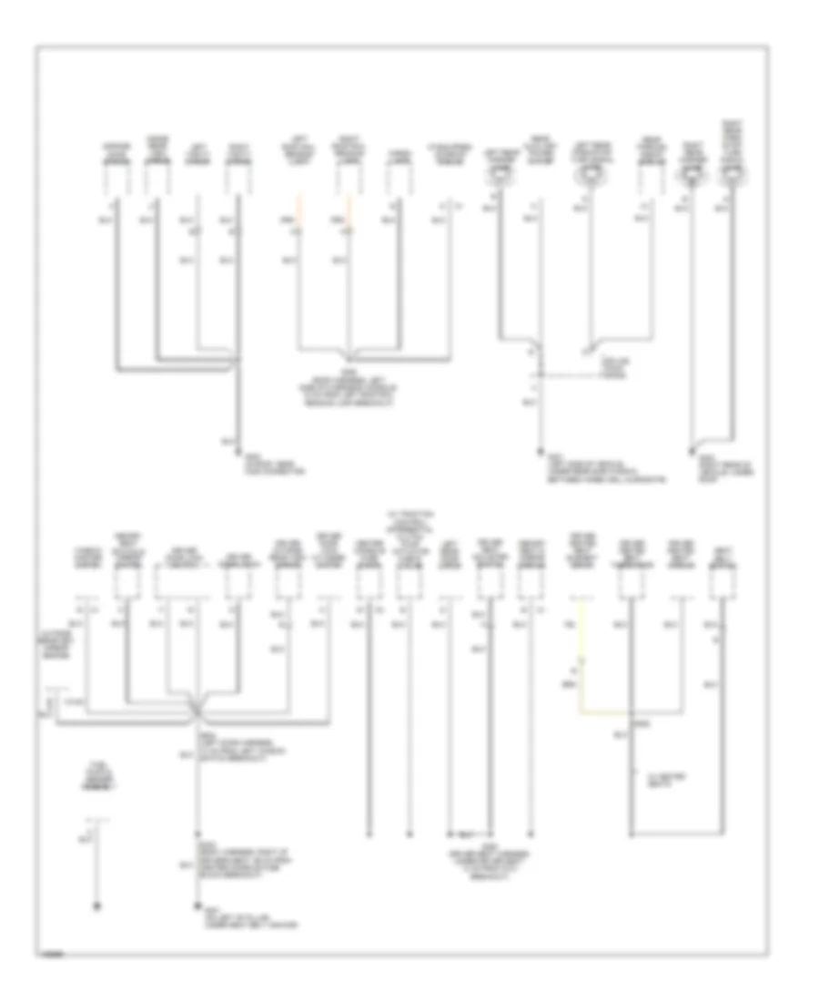
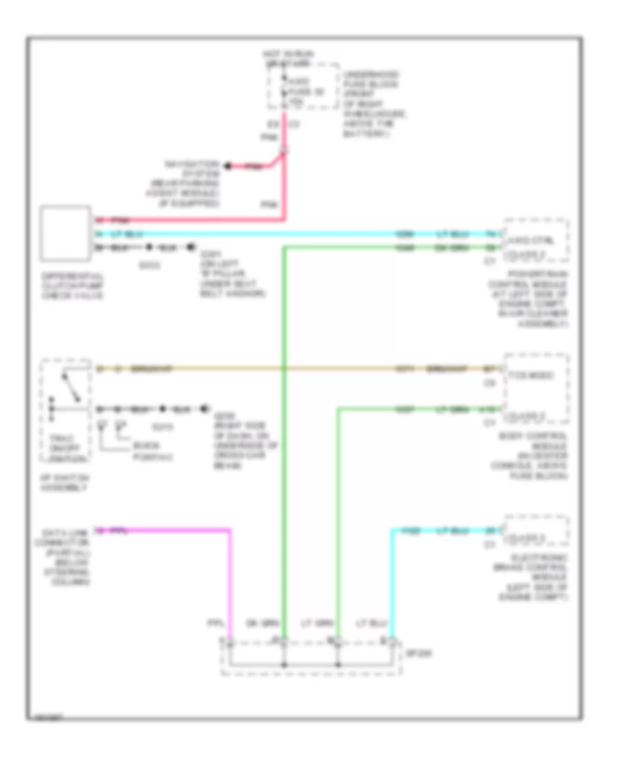
Ground Distribution Wiring Diagram (3 of 4) for Buick Rendezvous Ultra 2004
List of elements for Ground Distribution Wiring Diagram (3 of 4) for Buick Rendezvous Ultra 2004:
- (if equipped) sunroof module
- (w/ traction control) differential clutch pump actuator check valve
- (w/43)
- Cargo lamp
- Center console fuse block
- Driver door latch
- Driver door lock cylinder switch
- Driver door lock switch
- Driver heated seat element (back)
- Driver heated seat module
- Driver heated seat thermistor
- Driver outside rear view mirror
- Driver seat adjuster switch
- Fuel pump & sender assembly
- G301 (on left "b" pillar, under seat belt anchor)
- G303 (in roof, near c308 connector)
- G401 (left side of vehicle, under rear side window, between wheelwell & endgate)
- G402 (right rear of vehicle, under roof)
- Garage door opener
- Inside rear view mirror
- Left rear door latch
- Left rear marker lamp
- Left rear park/stop/ turn signal lamp
- Left roof rail reading lamp
- Left vanity mirror
- Memory seat & mirror module
- Memory seat switch & mirror switch
- Outside rearview mirror switch
- Rear auxiliary power outlet
- Rear parking assist module
- Right rear marker lamp
- Right rear park/ stop/ turn signal lamp
- Right roof rail reading lamp
- Right vanity mirror
- S333 (body harness, right of driver's seat, 66 cm from center console fuse block breakout)
- S350 (driver seat harness, under driver seat, 13 cm from c313 breakout)
- S352
- S390 (roof harness, left side of overhead console, 15 cm from left roof rail reading lamp breakout)
- S504 (left door harness, 10 cm from left window switch breakout)
- Seat belt switch
- Splice pack sp409
- W/ heated seats
- Window master switch
Ground Distribution Wiring Diagram (4 of 4) for Buick Rendezvous Ultra 2004
List of elements for Ground Distribution Wiring Diagram (4 of 4) for Buick Rendezvous Ultra 2004:
- (w/ auto level control) automatic level control compressor
- (w/ auto level control) automatic level control sensor
- A18
- Center high mounted stop lamp
- Front passenger door latch
- Front passenger door lock cylinder switch
- Front passenger door lock switch
- Front passenger seat adjuster switch
- Front passenger window switch
- G302 (on right "b" pillar, under seat belt anchor)
- G401 (left side of vehicle, under rear side window, between wheelwell & endgate)
- G403 (left rear of vehicle, under roof)
- Inflatable restraint sensing & diagnostic module (sdm)
- Liftgate lamp assembly
- Liftgate latch
- Nca
- Passenger back heated seat element (cushion)
- Passenger heated seat module
- Passenger heated seat thermistor
- Passenger rearview outside mirror
- Rear window defogger
- Rear window wiper motor
- Right rear door latch
- S301 (body harness, left rear of vehicle, 25 cm from pass-through)
- S303 (body harness, on right "b" pillar, 80 cm from inflatable restraint sensing & diagnostic module breakout)
- S351 (passenger seat harness, under passenger seat, 13 cm from c314 breakout)
- S353
- S604 (right door harness, 10 cm from right window switch breakout)
- W/ heated seats
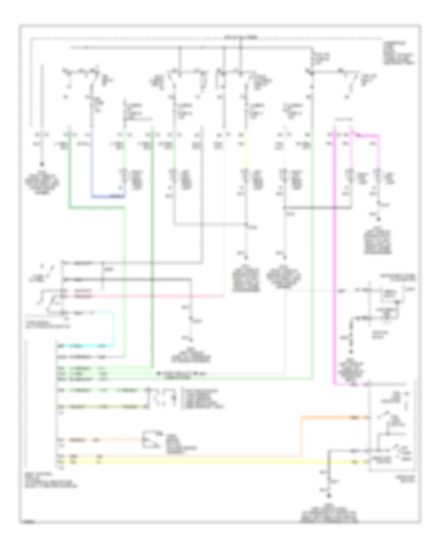
HEADLIGHTS
Headlights Wiring Diagram for Buick Rendezvous Ultra 2004
List of elements for Headlights Wiring Diagram for Buick Rendezvous Ultra 2004:
- A10
- A12
- B12
- Body control module (in console, above fuse block, in center console)
- Buick
- C2 b3
- C3 f5
- Computer data lines system
- Daytime running lamp ambient light sensor (center of dash, near defrost vent)
- Drl fuse 10a
- Drl relay
- Flash to pass
- Fog lamp indicator
- Fog lamp switch
- Fog lps fuse 26 10a
- Fog lps relay
- G100 (right side of engine compt, on top of front end upper cross member)
- G101 (left side of engine compt, right of left headlamp, on front upper crossmember)
- G201 (left side of dash, on underside of cross-car beam)
- G202 (left side of dash, on underside of cross-car beam, between park brake assembly & steering column)
- Hdlp hi beam relay
- Hdlp lo beam relay
- Head
- Headlamp switch
- Hi beam lt fuse 18 10a
- Hi beam rt fuse 23 10a
- High beam ind
- Hot at all times
- Ign
- Instrument panel cluster (ipc)
- Left fog lamp
- Left high beam head- lamp
- Left low beam head- lamp
- Lo beam lt fuse 17 10a
- Lo beam rt fuse 15 10a
- Logic
- Off
- Park
- Park brake switch (on park brake assembly
- Pontiac
- Right fog lamp
- Right high beam head- lamp
- Right low beam head- lamp
- S123
- S124
- S125
- S211
- S243
- S269
- Serial data
- Turn signal/ multi-function switch
- Underhood fuse block (front of right wheelhouse, above battery)
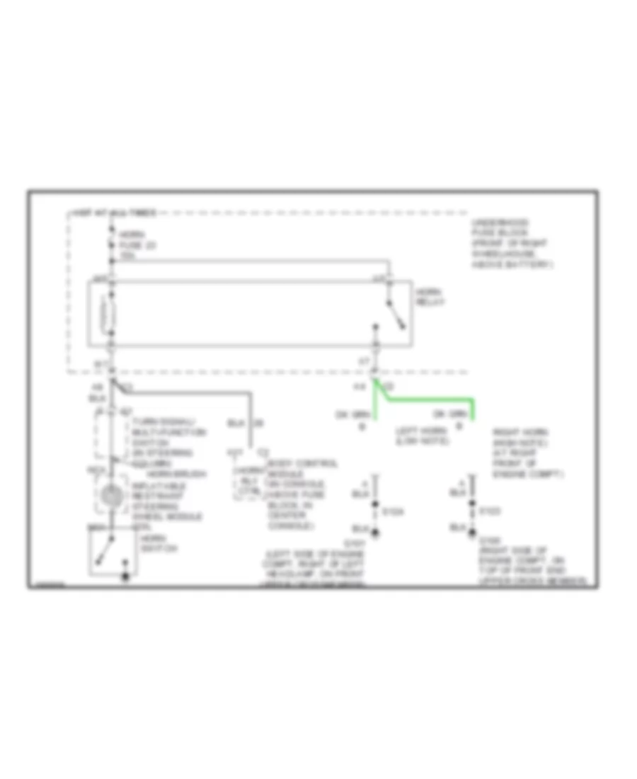
HORN
Horn Wiring Diagram for Buick Rendezvous Ultra 2004
List of elements for Horn Wiring Diagram for Buick Rendezvous Ultra 2004:
- A11
- Body control module (in console, above fuse block, in center console)
- G100 (right side of engine compt, on top of front end upper cross member)
- G101 (left side of engine compt, right of left headlamp, on front upper crossmember)
- Horn brush
- Horn fuse 23 15a
- Horn relay
- Horn rly ctrl
- Horn switch
- Hot at all times
- Inflatable restraint steering wheel module coil
- Left horn (low note)
- Nca
- Right horn (high note) (at right front of engine compt)
- S123
- S124
- Turn signal/ multi-function switch (in steering column)
- Underhood fuse block (front of right wheelhouse, above battery)
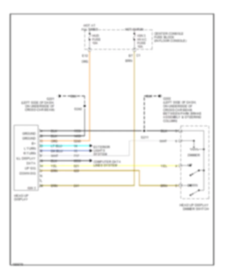
INSTRUMENT CLUSTER
Head-Up Display Wiring Diagram for Buick Rendezvous Ultra 2004
List of elements for Head-Up Display Wiring Diagram for Buick Rendezvous Ultra 2004:
- Center console fuse block (in floor console)
- Computer data lines system
- Data
- Dimmer
- Down
- Down sig
- E12
- Exterior lights system
- G201 (left side of dash, on underside of cross-car beam)
- G202 (left side of dash, on underside of cross-car beam, between park brake assembly & steering column)
- Ground
- Head up display
- Head up display dimmer switch
- Hot at all times
- Hot in run
- Hud fuse 10a
- Ign 3
- Ign 3 hvac fuse 10a
- Ill display
- L turn
- R turn
- S211
- S242
- Up sig
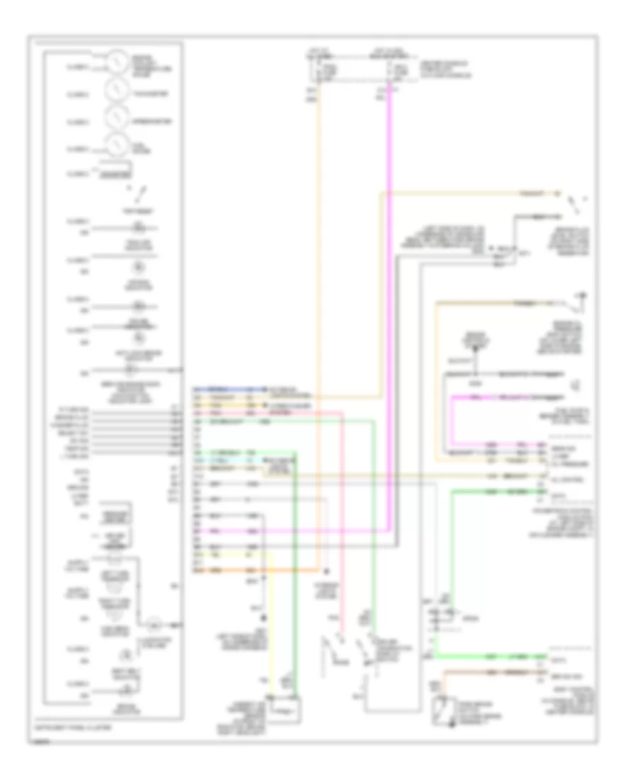
Instrument Cluster Wiring Diagram for Buick Rendezvous Ultra 2004
List of elements for Instrument Cluster Wiring Diagram for Buick Rendezvous Ultra 2004:
- (left side of dash, on underside of cross-car beam, between park brake assembly & steering column) g202
- A10
- A11
- A12
- Air bag indicator
- Ambient air temperature sensor (in front of radiator, behind right headlight)
- Anti-lock brake indicator
- B10
- B11
- B12
- Batt
- Body control module (in console, above fuse block, in center console)
- Brake fluid
- Brake fluid level switch (on right side of brake fluid reservoir)
- Brake indicator
- Brk sw sig
- C10
- Center console fuse block (in floor console)
- Class 2
- Cruise indicator
- Data
- Driver info center
- Driver information display switch set
- Engine controls system
- Engine coolant temperature gauge
- Engine oil pressure (eop) switch (on lower left side of engine, above starter)
- Exterior lights system
- Fuel gauge
- Fuel pump & sender assembly (in fuel tank)
- G201 (left side of dash, on underside of cross-car beam)
- Ground
- High beam indicator
- Hot at all times
- Hot in acc, run or start
- Ign
- Ign 0 fuse 2a
- Illumination (8 bulbs)
- Instrument panel cluster
- Interior lights system
- Ipc
- Ipmdl fuse 10a
- L turn sig
- Left turn indicator
- Lo ref
- Message center
- Mil control
- Mode
- Nca
- Odometer
- Oil pressure
- Park brake switch (on park brake assembly)
- Pnk
- Powertrain control module (pcm) (at left side of engine compt, in air cleaner assembly)
- R turn sig
- Right turn indicator
- S211
- S242
- S329
- Seat belt indicator
- Select sw
- Sens sig
- Service engine soon indicator (malfunction indicator lamp)
- Sp205
- Speedometer
- Sw sig
- Tachometer
- Tan
- Temp sig
- Trac off indicator
- Trip reset
- Washer fluid
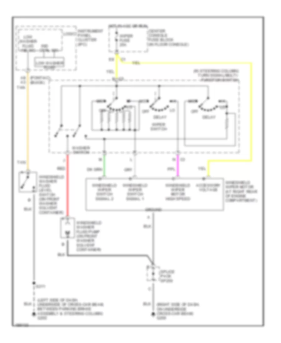
- Wiper/washer system
INTERIOR LIGHTS
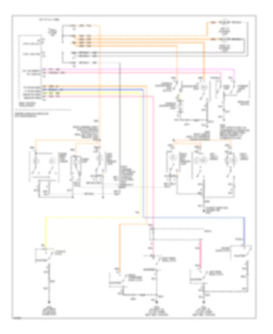
Courtesy Lamps Wiring Diagram for Buick Rendezvous Ultra 2004
List of elements for Courtesy Lamps Wiring Diagram for Buick Rendezvous Ultra 2004:
- (in roof, near c308 connector) g303
- (roof harness, right side of overhead console, 64 cm from left roof rail reading lamp) s393
- 40 cm from g303 breakout) s397
- A10
- Bcm l fuse 20a
- Body control module (bcm)
- Cargo lamp
- Center console fuse block (in floor console)
- Console compartment lamp
- Console compartment lamp switch
- Courtesy
- Ctsy lps ctrl
- Ctsy lps volt
- Dome lamp
- Driver door latch
- Endgate open
- Front passenger door latch
- G200 (right side of dash, on underside cross-car beam)
- G202 (left side of dash, on underside of cross-car beam, between park brake assembly & steering column)
- G301 (on left "b" pillar, under seat belt anchor)
- G302 (on right "b" pillar, under seat belt anchor)
- G403 (left rear of vehicle, under roof)
- Headlamp switch
- Hot at all times
- I/p compartment lamp
- Inside rear view mirror
- Int lmp defeat
- Int lmps on
- Interior lamps off
- Left i/p courtesy lamp
- Left rear door latch
- Left roof rail reading lamp
- Left vanity mirror
- Liftgate latch
- Lt fr dr open
- Pnk
- Rear dr open
- Right i/p courtesy lamp
- Right rear door latch
- Right roof rail reading lamp
- Right vanity mirror
- Rt fr dr open
- S211
- S213
- S214
- S303
- S390
- S504
- S604
- S907
- Sp315
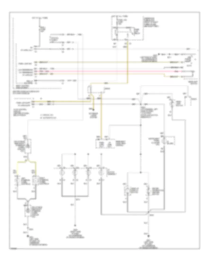
Instrument Illumination Wiring Diagram (1 of 2) for Buick Rendezvous Ultra 2004
List of elements for Instrument Illumination Wiring Diagram (1 of 2) for Buick Rendezvous Ultra 2004:
- (8 bulbs)
- 12v reference
- A manual a/c
- Auto
- B automatic a/c
- B c1
- B c3
- B12
- Bcm l fuse 20a
- Body control module (bcm)
- C2 b
- C4 b
- Center console fuse block (in floor console)
- D10
- Driver information center switch
- E10
- Exterior lamps system
- G200 (right side of dash, on underside of cross-car beam)
- G201 (left side of dash, on underside of cross-car beam)
- G202 (leftside of dash, on underside of cross-car beam)
- Head
- Head up display switch
- Head- lamp switch
- Headlamp switch
- Hot at all times
- Hvac control module (center of dash, below radio)
- I/p lmps dim
- I/p lmps supp
- I/p lmps volt
- I/p switch assembly
- Inflatable restraint steering wheel module coil
- Instrument panel cluster (ipc)
- Left steering wheel controls
- Low reference
- Nca
- Off
- Park
- Park lamp sig
- Park lmp supp
- Park lmps volt
- Park lps fuse 15a
- Park lps relay
- Pnk
- Prk lp rly ctrl c3
- Radio
- Rear seat audio (rsa) control
- Right steering wheel controls
- S203 (i/p harness, left side of dash, 13 cm from stoplamp switch breakout)
- S211
- S213
- S242
- S243
- Sp250
- Stg col fuse 2 2a
- Underhood fuse block (front of right wheelhouse, above battery)
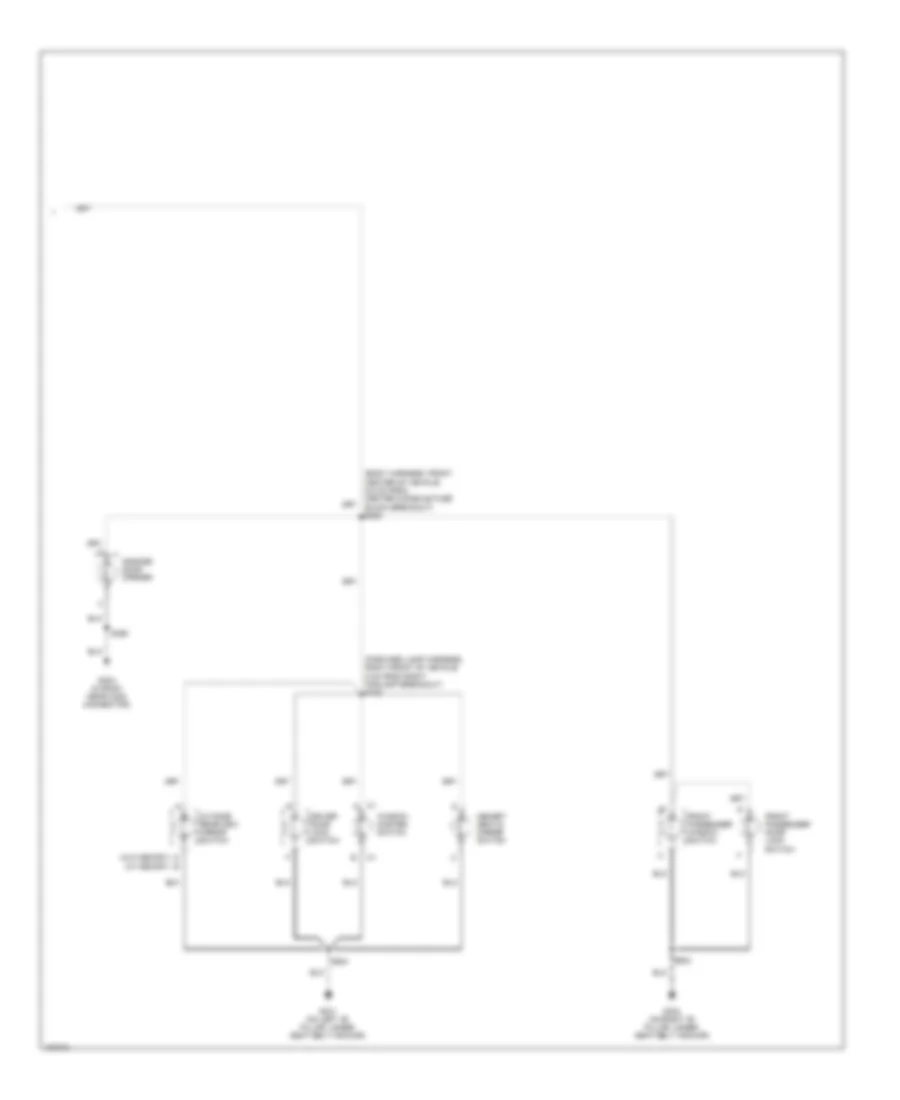
Instrument Illumination Wiring Diagram (2 of 2) for Buick Rendezvous Ultra 2004
List of elements for Instrument Illumination Wiring Diagram (2 of 2) for Buick Rendezvous Ultra 2004:
- (body harness, front center of vehicle, 6.5 cm from center console fuse block breakout) s320
- (forward lamp harness, right front of vehicle, 5 cm from right foglamp breakout) s102
- (w/ memory)
- (w/o memory)
- Driver door lock switch
- Front passenger door lock switch
- Front passenger window switch
- G301 (on left "b" pillar, under seat belt anchor)
- G302 (on right "b" pillar, under seat belt anchor)
- G303 (in roof, near c308 connector)
- Garage door opener
- Memory seat & mirror switch
- Outside rearview mirror switch
- S390
- S504
- S604
- Window master switch
MEMORY SYSTEMS
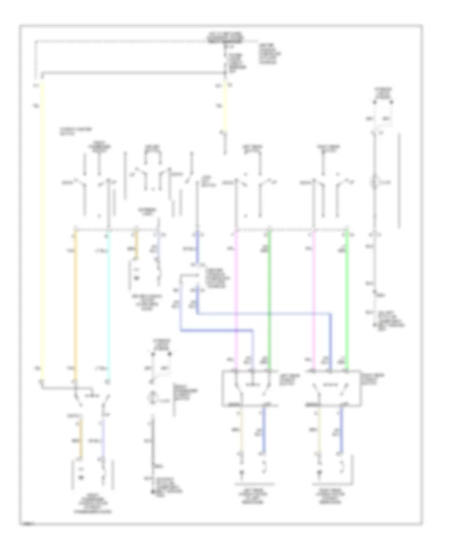
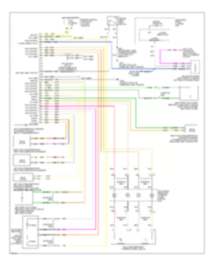
Memory Seat & Mirrors Wiring Diagram for Buick Rendezvous Ultra 2004
List of elements for Memory Seat & Mirrors Wiring Diagram for Buick Rendezvous Ultra 2004:
- (on left "b" pillar, under seat belt anchor)
- 5v ref
- A10
- A11
- A12
- Aft
- B10
- B11
- B12
- Bat (+)
- C2 b4
- Center console fuse block (in floor console)
- Class 2 serial data
- Computer data lines system
- Dr seat sw pwr
- Dr st frt vert dn sw
- Dr st frt vert pos sen
- Dr st frt vert up sw
- Dr st hori fwd sw
- Dr st hori pos sen
- Dr st hori rwd sw
- Dr st rr vert dn sw
- Dr st rr vert pos sen
- Dr st rr vert up sw
- Driver outside rearview mirror
- Driver seat adjuster motor assembly
- Driver seat adjuster switch
- Driver seat position sensor
- Exit
- Fore
- Front up/down
- Front vertical
- Frt dn
- Frt up
- Frt vert mtr dn ctrl
- Frt vert mtr up ctrl
- G301
- Gnd
- Hori- zontal
- Horiz mtr fwd ctrl
- Horiz mtr rwd ctrl
- Horizontal for/aft
- Hot at all times
- Interior lights system
- Left
- Low ref
- Lt mir hor pos sen
- Lt mir mtr dn ctrl
- Lt mir mtr lt ctrl
- Lt mir mtr rt ctrl
- Lt mir sw dn sig
- Lt mir sw rt sig
- Lt mir ver pos sen
- Mem
- Memory 1 sw sig
- Memory 2 sw sig
- Memory seat & mirror module (under driver seat)
- Memory seat & mirror switch
- Mir mtr left/up ctrl
- Mir sw pwr
- Nca
- Outside rearview mirror switch
- Passenger outside rearview mirror
- Pwr sts circuit breaker 11 30a
- Rear up/down
- Rear vertical
- Rr dn
- Rr up
- Rr vert mtr dn ctrl
- Rr vert mtr up ctrl
- Rt mir hor pos sen
- Rt mir mtr dn ctrl
- Rt mir mtr lt ctrl
- Rt mir mtr rt ctrl
- Rt mir sw dn sig
- Rt mir sw rt sig
- Rt mir ver pos sen
- S333
- S340
- S350
- S504
- Tan
- Vertical
NAVIGATION
Parking Assistant Wiring Diagram for Buick Rendezvous Ultra 2004
List of elements for Parking Assistant Wiring Diagram for Buick Rendezvous Ultra 2004:
- Awd fuse 30 15a
- Backup lamp voltage
- Body control module (in console above fuse block, in center console)
- C1 b8
- C1 f
- C11
- Center amber ind ctrl
- Center amber indicator
- Center console fuse block (in floor console)
- Diagnostic input
- Engine controls system
- G200 (right side of dash, on underside of cross-car beam)
- G401 (left side of vehicle, under rear side window, between wheelwell & endgate)
- Ground
- Hot in run or start
- I/p switch assembly
- Ign3 hvac fuse 26 10a
- Left amber ind ctrl
- Left amber indicator
- Left rear corner object sensor (behind left corner of rear bumper)
- Left rear middle object sensor (behind middle of rear bumper)
- Low ref
- Lr corner sensor sig
- Lr middle sensor sig
- Mirrors system
- Park aid
- Park assist sw sig
- Pnk
- Power distribution system
- Rear park chime sig
- Rear parking assist (rpa) diagnostic connector
- Rear parking assist (rpa) display
- Rear parking assist (rpa) module (behind front center dash console)
- Red
- Red ind ctrl
- Red indicator
- Right rear corner object sensor (behind right corner of rear bumper)
- Right rear middle object sensor (behind middle of rear bumper)
- Rr corner sensor sig
- Rr middle sensor sig
- S213
- S401
- S402
- Sensor low ref
- Sensor signal
- Sensor voltage
- Splice pack sp250
- Splice pack sp409
- Telltail assy voltage
- Transaxle range switch (on top of transaxle)
- Trnsig fuse 19 10a
- Underhood fuse block (front of right wheelhouse, above battery)
- Vss signal
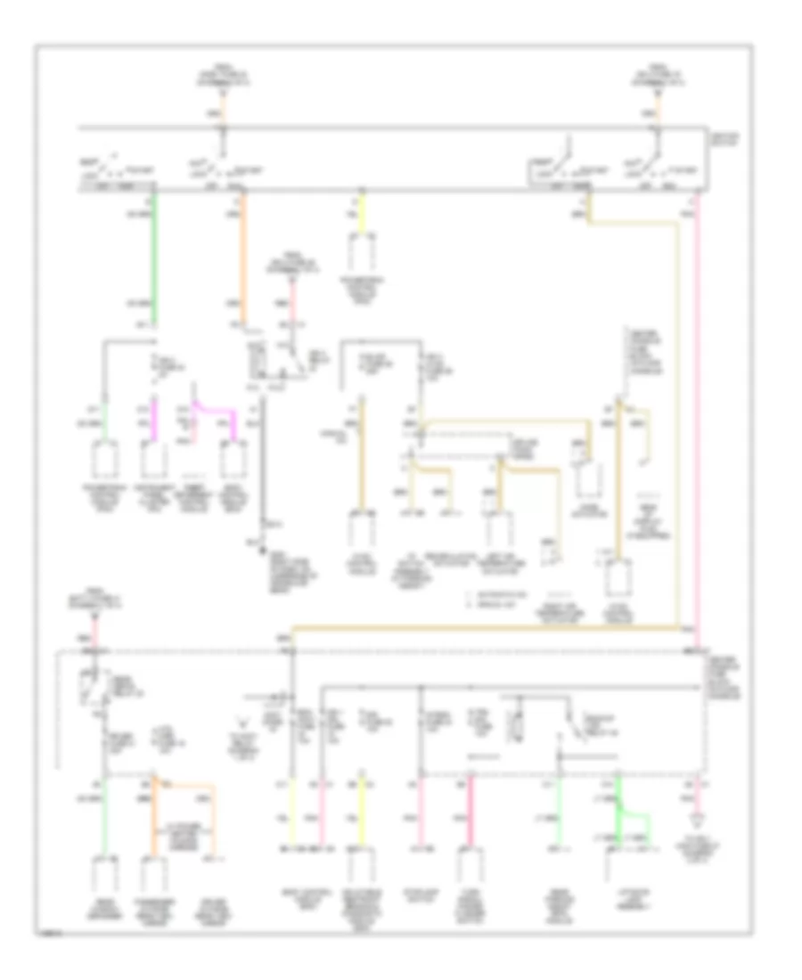
POWER DISTRIBUTION
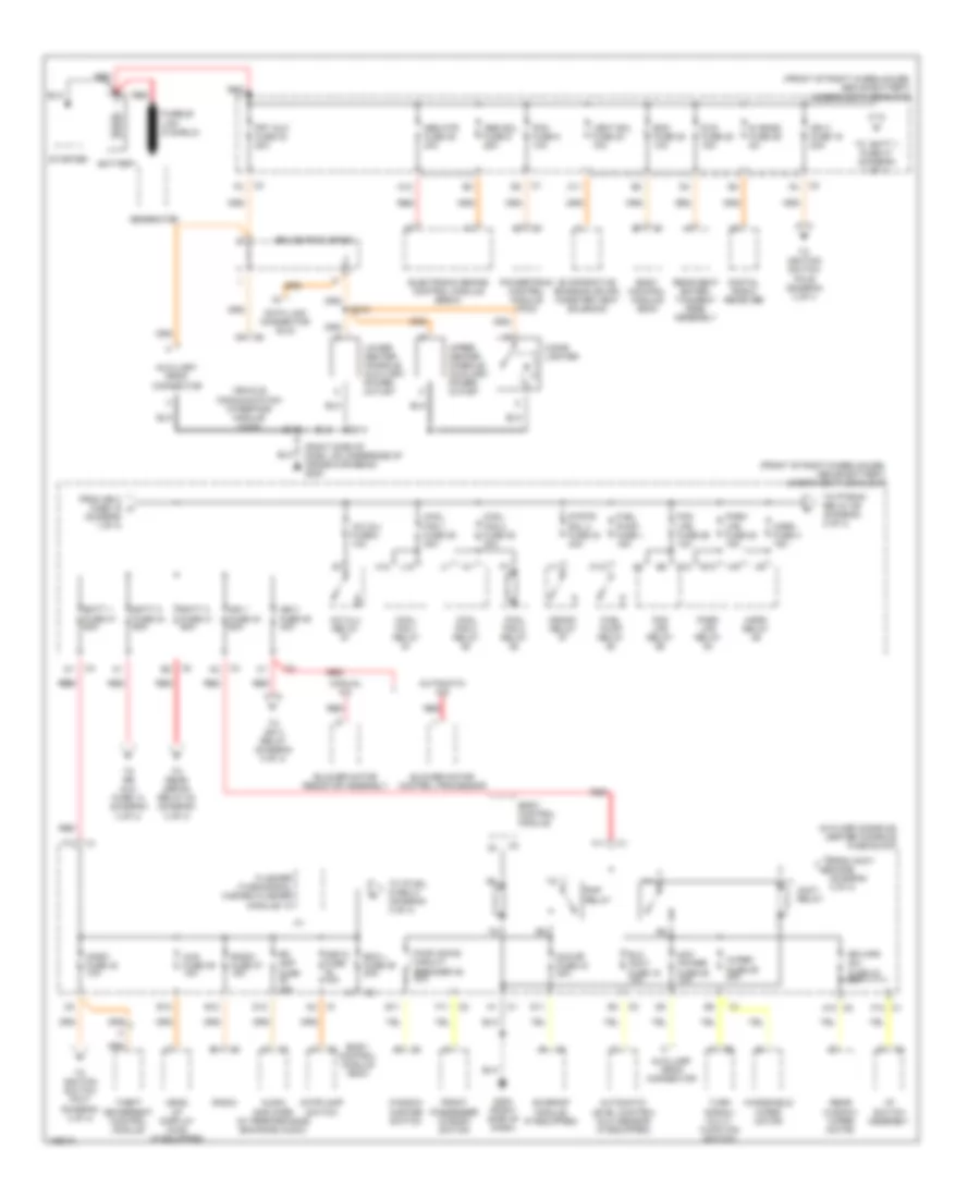
Power Distribution Wiring Diagram (1 of 4) for Buick Rendezvous Ultra 2004
List of elements for Power Distribution Wiring Diagram (1 of 4) for Buick Rendezvous Ultra 2004:
- (diagram 1 of 4)
- (diagram 3 of 4)
- (front of right wheelhouse, above battery) underhood fuse block
- (in floor console) center console fuse block
- (right side of dash, on underside of cross-car beam) g200
- A/c clu fuse 2 10a
- A/c clu relay
- A12
- Abs mtr fuse 35 40a
- Abs sol fuse 9 25a
- Acc power fuse 28 10a
- Accy relay
- Audio amplifier (w/ performance enhance audio)
- Automatic a/c
- Automatic level control (alc) sensor (if equipped)
- Auxiliary drop connector
- B12
- Batt 1 fuse 47 60a
- Batt 2 fuse 44 60a
- Batt 3 fuse 41 60a
- Battery
- Bcm fuse 28 10a
- Bcm l fuse 36 20a
- Blower motor control processor
- Blower motor resistor assembly
- Body control module
- Body control module (bcm)
- C1 f10
- C11
- C2 a10
- Cigar lighter
- Cool fan 1 fuse 39 30a
- Cool fan 1 relay
- Cool fan 2 fuse 38 30a
- Cool fan 2 relay
- Cool fan 3 relay
- Crank relay
- D10
- D11
- D12
- Data link connector (dlc)
- Digital radio receiver
- Dvd fuse 25 15a
- E10
- E11
- E12
- Elc accy fuse 15 10a
- Electronic brake control module (ebcm)
- Evaporative emission (evap) canister vent solenoid
- F11
- F12
- Flasher (turn/signal hazard flasher module) 10
- Fog lps fuse 26 10a
- Fog lps relay
- From accy diode k
- From ign 3 fuse 19 a
- Front passenger window switch
- Frt aux fuse 32 20a
- Fuel pump fuse 1 15a
- Fuel pump relay
- G200 (right side of dash)
- Generator
- H12
- Head up display (hud) (if equipped)
- Horn fuse 3 15a
- Horn relay
- Hud fuse 39 10a
- Hzd fl fuse 15a
- I/p switch assembly
- Ign 1 fuse 40 60a
- Ign 3 fuse 19 20a
- Ign 3 fuse 46 40a
- Inkey fuse 42 10a
- J12
- Lower center console auxiliary power outlet
- Manual a/c
- Park lps fuse 20 15a
- Park lps relay
- Pcm fuse 5 10a
- Powertrain control module (pcm)
- Pwr wdws circuit breaker 35 30a
- Radio
- Radio fuse 37 15a
- Rap relay
- Rd amp fuse 25a
- Rear seat enter- tainment (rse) assembly
- Rear window wiper motor
- Red
- Red red
- Rr wpr sw fuse 32 20a
- S- band fuse 29 5a
- S213
- S214
- S215
- Splice pack sp250
- Starter
- Stoplamp switch
- Strtr sol 2 fuse 34 40a
- Sun rf fuse 34 20a
- Sunroof module (if equipped)
- Theft deterrent control module
- To batt 1 fuse 47 (diagram 1 of 4)
- To ign 3 relay (diagram 3 of 4)
- To ignition switch pin b (diagram 3 of 4
- To ignition switch pin f (diagram 3 of 4)
- To ip mdl fuse 41 (diagram 4 of 4)
- To ptrain relay 59 (diagram 2 of 4)
- To rear defog relay 20 (diagram 3 of 4)
- To rr aux fuse 14 (diagram 4 of 4)
- Turn signal/ multi- function switch
- Upper center console auxiliary power outlet
- Vehicle communication interface module (vcim)
- Vent sol fuse 24 10a
- W12
- Window master switch
- Windshield wiper motor
- Wiper fuse 29 25a
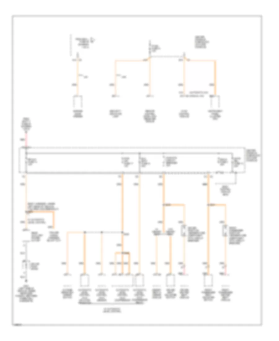
Power Distribution Wiring Diagram (2 of 4) for Buick Rendezvous Ultra 2004
List of elements for Power Distribution Wiring Diagram (2 of 4) for Buick Rendezvous Ultra 2004:
- (front of right wheelhouse, above battery) underhood fuse block
- (fuel injector pnk
- 1-2 shift solenoid (1-2 ss) valve
- 2-3 shift solenoid (2-3 ss) valve
- 3.4l
- 3.6l
- A/c clu relay
- Abs fuse 4 10a
- Abs fuse 6 10a
- Automatic transaxle
- Awd fuse 30 15a
- B10
- Btsi fuse 33 2a
- C111 e
- Crank relay 59
- Cruise control module
- Cruise control release switch
- Cruise control switch
- Cruise fuse 31 10a
- D12
- Differential clutch pump actuator check valve (electronic traction control)
- Drl relay 52
- E11
- E12
- Ecm fuse 5 10a
- Elec eng fuse 13 15a
- Electronic brake control module (ebcm)
- Eng controls fuse 4 10a
- Engine control module (ecm)
- Evaporative emissions (evap) canister purge solenoid
- F11
- F12
- From horn fuse 3 c (diagram 1 of 4)
- From ignition relay 59 diagram (2 of 4)
- From turn sig fuse 19 (center console fuse block) (diagram 3 of 4)
- Fuel inj fuse 11 15a
- Fuel injector
- G111 (engine compt, on bellhousing, left of starter)
- Harness, 39 cm from c102) s109
- Hdlp hi beam relay 55
- Hdlp lo beam relay 53
- Heated oxygen sensor (ho2s)
- Ign 1 main fuse 27 10a
- Ignition control module (icm)
- Ignition relay 59 (3.4l) ignition relay 62 (3.6l)
- M11
- Mass air flow (maf) sensor
- N11
- Nca
- O2 sensors fuse 10 15a
- Pnk
- Powertrain control module (pcm)
- Ptrain relay 59 (3.6l)
- Rear parking assist (rpa) module
- Red
- S106
- S115
- Stoplamp switch
- Tcm fuse 8 10a
- To o2 sensors fuse 10 (diagram 2 of 4)
- Torque converter clutch (tcc) solenoid valve
- Trans sol fuse 7 10a
- Transmission control module (tcm)
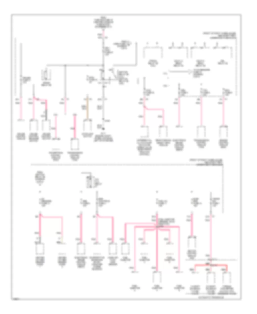
Power Distribution Wiring Diagram (3 of 4) for Buick Rendezvous Ultra 2004
List of elements for Power Distribution Wiring Diagram (3 of 4) for Buick Rendezvous Ultra 2004:
- A10
- A11
- Acc
- Accy diode
- Automatic a/c
- Backup lps relay 45
- Bcm- accy fuse 10a
- Blwr fuse 25 25a
- Body control module (bcm)
- C10
- C11
- Center console fuse block (in floor console)
- D10
- D11
- Driver outside rear view mirror
- E11
- From batt 3 fuse 41 (diagram 1 of 4)
- From ign 3 fuse 19 (diagram 1 of 4)
- From ign 3 fuse 46 (diagram 1 of 4)
- From inkey fuse 42 (diagram 1 of 4)
- G200 (right side of dash, on underside of cross-car beam)
- Head up display (hud) (if equipped)
- Htd mirr fuse 16 10a
- Hvac control module
- I/p switch assembly (w/ parking assist)
- Ign 0 fuse 30 2a
- Ign 1 mdl fuse 10a
- Ign 3 hvac fuse 26 10a
- Ign 3 relay
- Ignition switch
- Inflatable restraint sensing & diagnostic module (sdm)
- Instrument panel cluster (ipc)
- Intemm fuse 24 10a
- Left air temperature actuator
- Liftgate lamp assembly
- Lock
- M12
- M13
- Manual a/c
- Mode actuator
- Off
- P12
- P13
- Passenger outside rear view mirror
- Pnk
- Powertrain control module (pcm)
- Rear defog relay 20
- Rear parking assist (rpa) module
- Rear window defogger
- Recirculation actuator
- Red
- Right air temperature actuator
- Rr def fuse 21 30a
- Run
- S213
- Sir fuse 22 10a
- Splice pack sp250
- Start
- Stoplamp switch
- Theft theft deterrent control module
- To accy relay (diagram 1 of 4)
- To ign 1 main fuse 27 (diagram 2 of 4)
- Trn sig fuse 10a
- Turn signal/ hazard flasher switch
- W/ power heated folding mirrors
Power Distribution Wiring Diagram (4 of 4) for Buick Rendezvous Ultra 2004
List of elements for Power Distribution Wiring Diagram (4 of 4) for Buick Rendezvous Ultra 2004:
- (automatic a/c)
- (body harness, under left rear of vehicle, 7 cm from c302 breakout) s305
- (diagram
- (manual a/c)
- 1 of 4)
- A10
- A12
- A12 c2
- Automatic level control (alc) compressor
- Automatic level control (alc) compressor relay
- Automatic level control (alc) inflator air switch
- Automatic level control (alc) sensor
- B10
- B12
- Bcm d fuse 3 25a
- Body control module (bcm)
- Center console fuse block (in floor console)
- Driver heated seat module
- Driver positive temperature coefficient (ptc) circuit breaker
- Driver seat adjuster switch
- Elc batt fuse 12 30a
- From batt 2 fuse 44 (diagram 1 of 4)
- From bcm l fuse 36
- Front passenger heated seat module
- Front passenger positive temperature coefficient (ptc) circuit breaker
- Front passenger seat adjuster switch
- G401 (left side of vehicle, under rear side window, between wheelwell & endgate)
- Garage door opener
- Gate rel fuse 13 20a
- Hvac control module
- Instrument panel cluster (ipc)
- Ip mdl fuse 41 10a
- Memory seat & mirror module
- Outside rearview mirror switch
- Pwr mir fuse 17 10a
- Pwr sts circuit breaker 30a
- Rear auxiliary power outlet
- Red
- Remote control door lock receiver (rcdlr)
- Rr aux fuse 14 10a
- S340
- S341
- S420
- S425
- Security indicator lamp
- Splice pack sp409
- Ua5
- Ug1
- W/ automatic level control
- W/ memory seat
- W/o memory seat
POWER DOOR LOCKS
Power Door Locks Wiring Diagram for Buick Rendezvous Ultra 2004
List of elements for Power Door Locks Wiring Diagram for Buick Rendezvous Ultra 2004:
- (on left "b" pillar,
- (on right "b" pillar,
- A10
- Antenna
- Battery
- Bcm d fuse 25a
- Body control module (in console, above fuse block, in center console)
- Center console fuse block (in floor console)
- Class 2 serial data
- Door lock key unlock signal
- Door lock/ unlock switch
- Driver door lock actuator (in driver's door)
- Driver door lock cylinder switch
- Driver door lock switch
- Driver unlock
- Endgate lock
- Endgate unlock
- Front passenger door lock actuator (in front passenger's door)
- Front passenger door lock cylinder switch
- Front passenger door lock switch
- G202 (left side of dash, on underside of cross-car beam, between park brake assembly & steering column)
- G301
- G301 (on left "b" pillar, under seat belt anchor)
- G302
- Gate rel fuse 20a
- Ground
- Hot at all times
- Instrument panel cluster
- Interior lights system
- Ipmdl fuse 10a
- Key fob low battery
- Left rear door lock actuator (in left rear door)
- Liftgate lock actuator (in tailgate)
- Lock
- Logic
- Message center
- Power distribution system
- Remote control door lock receiver (behind center of dash, near windshield defrost vent, in sun roof assembly)
- Remote signal
- Right rear door lock actuator (in right rear door)
- S211
- S333
- S504
- S604
- Signal
- Sp205
- Tan
- Under seat belt anchor)
- Unlock
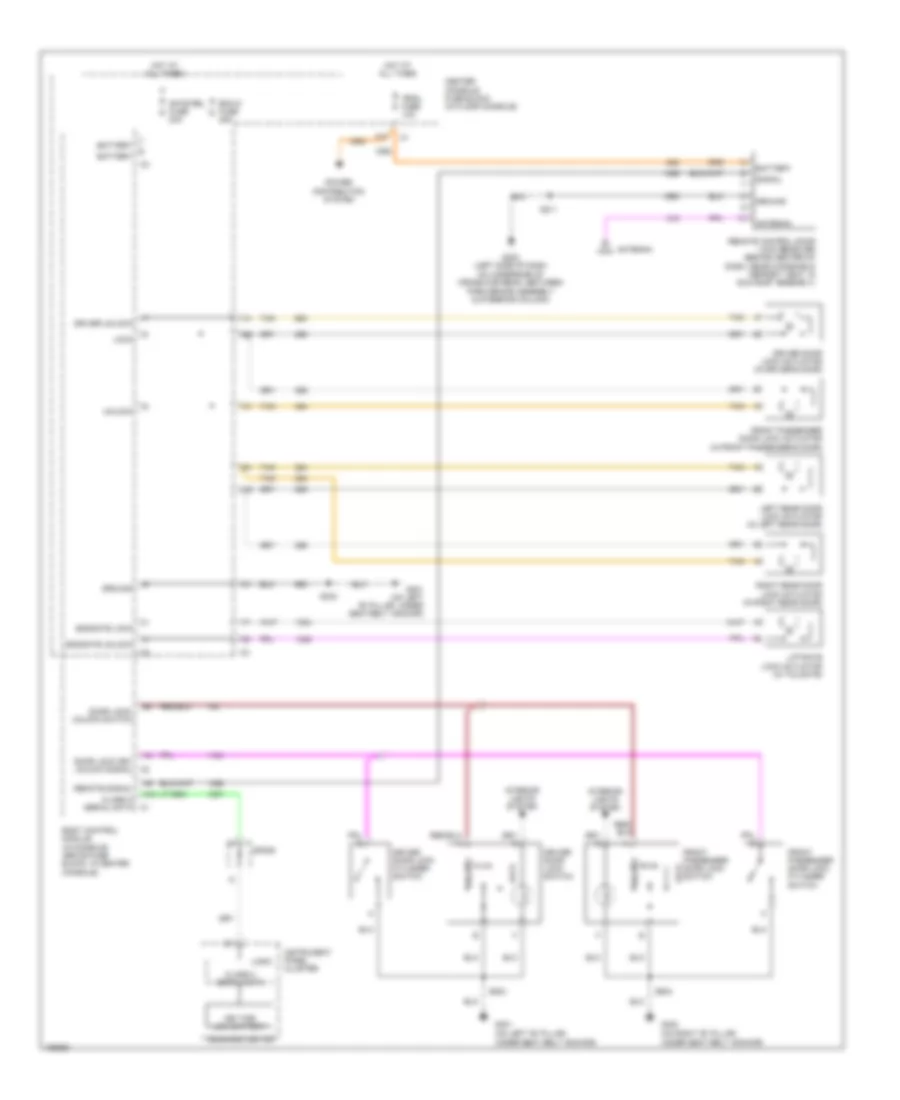
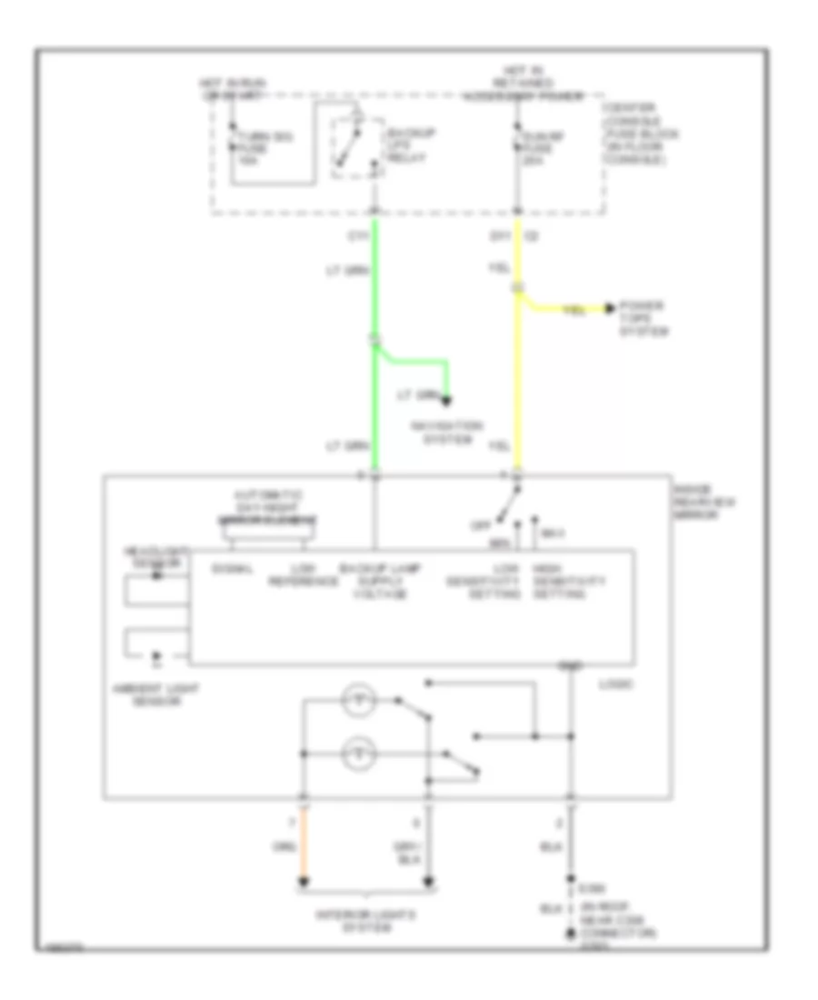
POWER MIRRORS
Electrochromic Mirror Wiring Diagram for Buick Rendezvous Ultra 2004
List of elements for Electrochromic Mirror Wiring Diagram for Buick Rendezvous Ultra 2004:
- (in roof, near c308 connector) g303
- Ambient light sensor
- Automatic day-night mirror element
- Backup lps relay
- C11
- Center console fuse block (in floor console)
- D11 c2
- Gnd
- Headlight sensor
- Hot in retained accessory power
- Hot in run or start
- Inside rearview mirror
- Interior lights system
- Logic
- Low high sensitivity setting
- Low reference
- Max
- Min
- Navigation system
- Off
- Power tops system
- S390
- Sensitivity setting
- Signal
- Sun rf fuse 20a
- Turn sig fuse 10a
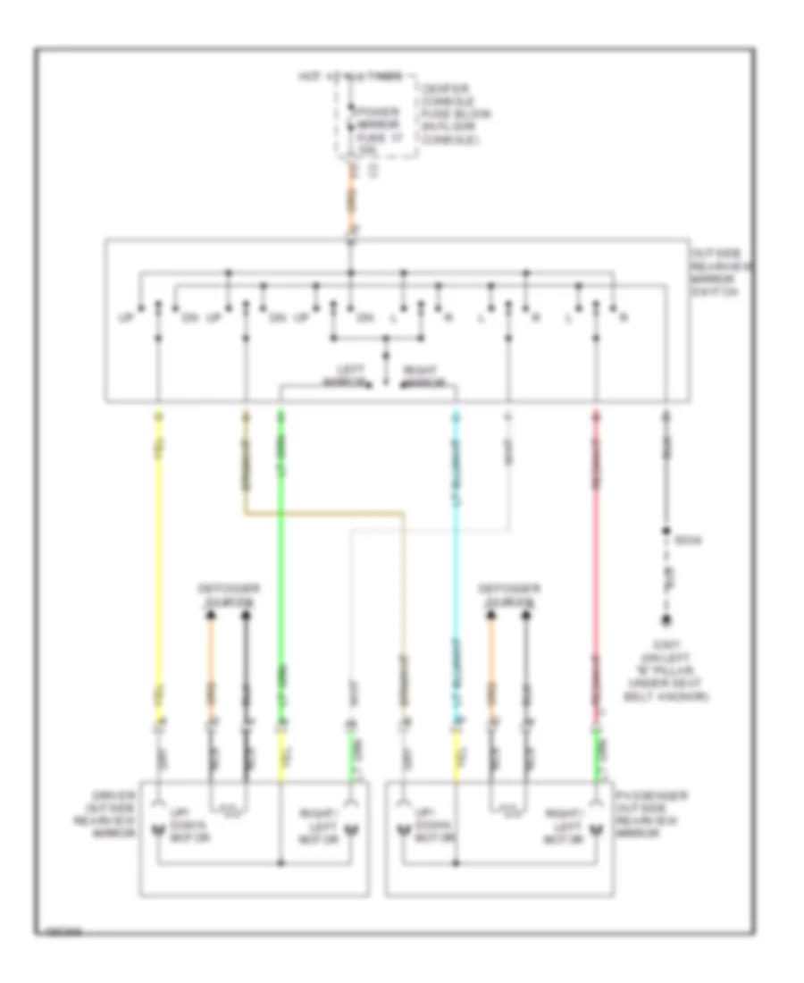
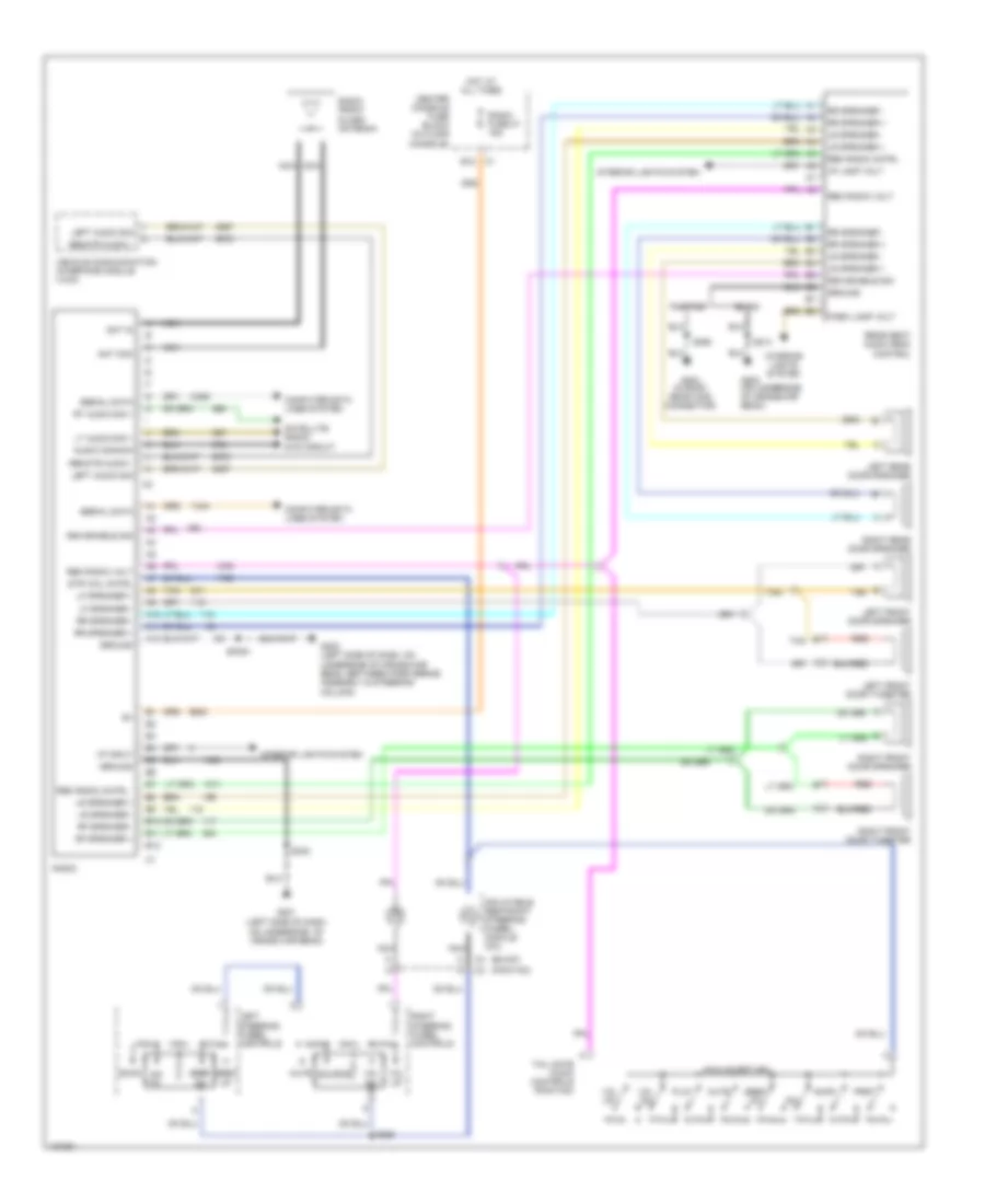
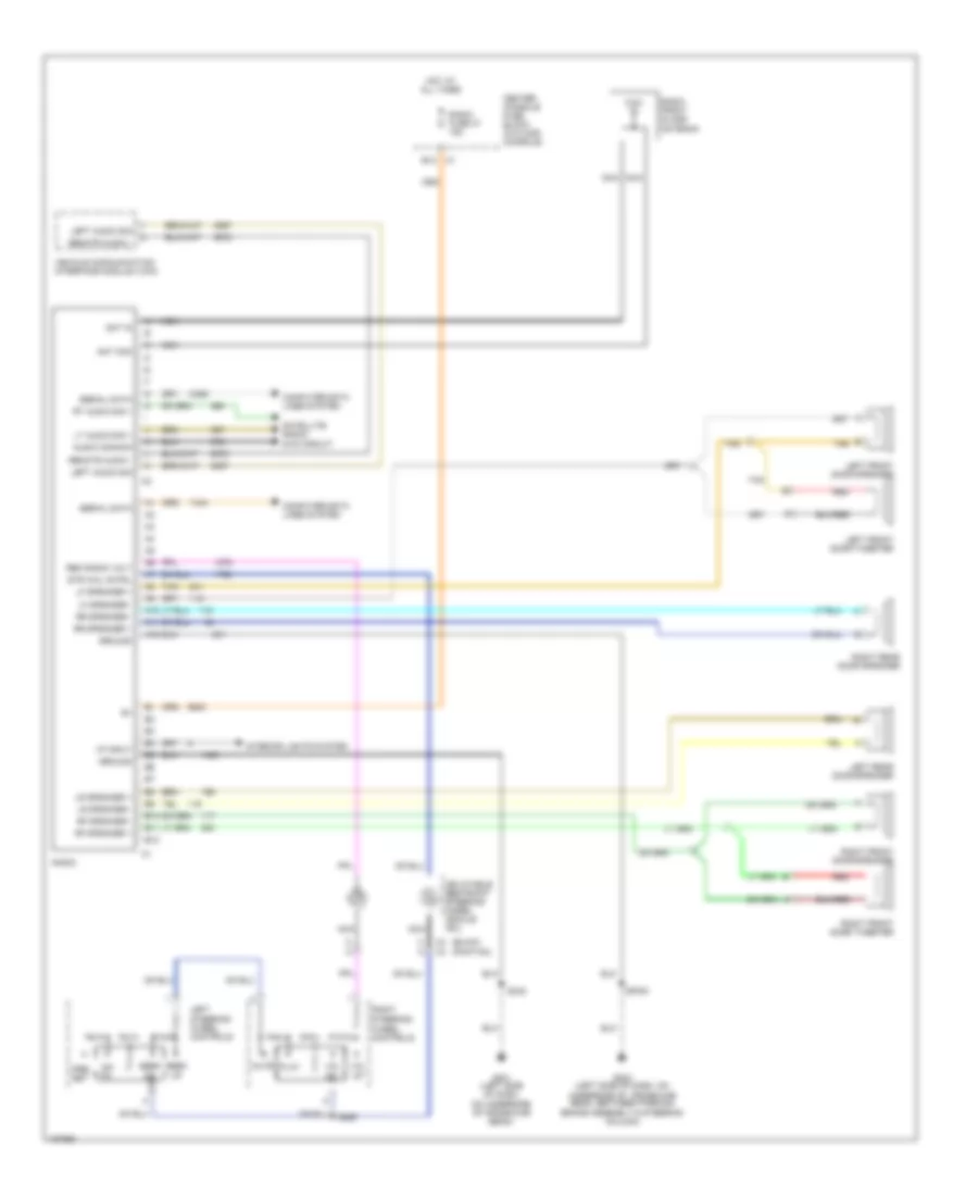
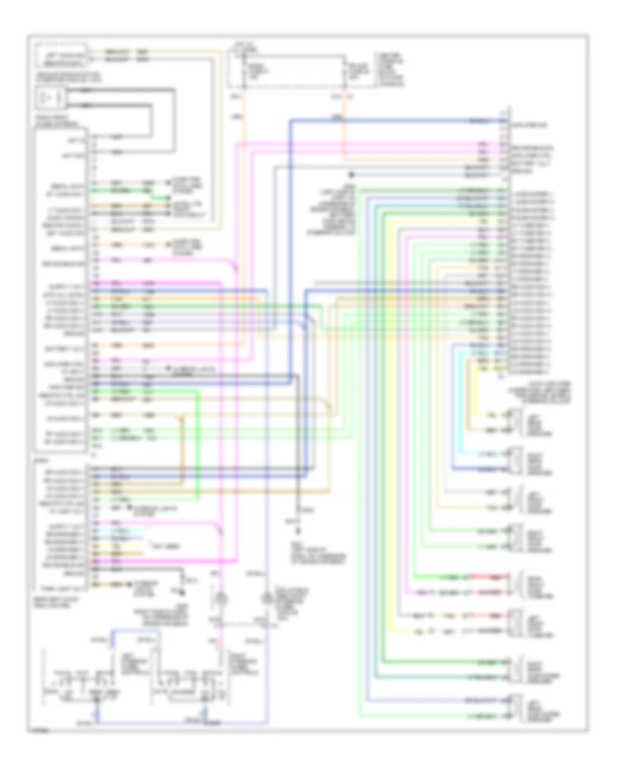
Power Mirrors Wiring Diagram for Buick Rendezvous Ultra 2004
List of elements for Power Mirrors Wiring Diagram for Buick Rendezvous Ultra 2004:
- Center console fuse block (in floor console)
- Defogger system
- Driver outside rearview mirror
- G301 (on left "b" pillar, under seat belt anchor)
- Hot at all times
- Left mirror
- Motor
- Nca
- Outside rearview mirror switch
- Passenger outside rearview mirror
- Power mirror fuse 17 10a
- Right mirror
- Right/ left m
- S504
- Up/ down m
POWER SEATS
6-Way Power Seat Wiring Diagram for Buick Rendezvous Ultra 2004
List of elements for 6-Way Power Seat Wiring Diagram for Buick Rendezvous Ultra 2004:
- Aft
- Back
- Center console fuse block (in floor console)
- Driver seat adjuster motor assembly
- Driver seat adjuster switch
- Fore
- Fore- hori- zontal motor
- Front passenger seat adjuster motor assembly
- Front passenger seat adjuster switch
- Front vert- ical motor
- Frt
- Frt dn
- Frt up
- G301 (on left "b" pillar, under seat belt anchor)
- G302 (on right "b" pillar, under seat belt anchor)
- Hori- zontal motor
- Hot at all times
- Pwr sts circuit breaker 30a
- Rear vert- ical motor
- Rr dn
- Rr up
- S340
- S341
- S350
- S351
- Tan
Heated Seats Wiring Diagram for Buick Rendezvous Ultra 2004
List of elements for Heated Seats Wiring Diagram for Buick Rendezvous Ultra 2004:
- Body control module (in console, above fuse block, in center console)
- C315
- C316
- C319
- C320
- Center console fuse block (in floor console)
- Driver
- Driver back heated seat element
- Driver back heated seat pad
- Driver cushion heated seat element
- Driver cushion heated seat pad
- Driver heated seat module
- Driver heated seat thermistor
- Driver positive temperature coefficient circuit breaker
- Front passenger
- Front passenger back heated seat element
- Front passenger back heated seat pad
- Front passenger cushion heated seat element
- Front passenger cushion heated seat pad
- Front passenger heated seat module
- Front passenger heated seat thermistor
- Front passenger positive temperature coefficient circuit breaker
- G200 (right side of dash, on underside of cross-car beam)
- G301 (on left "b" pillar, under seat belt anchor)
- G302 (on right "b" pillar, under seat belt anchor)
- Gnd
- Hot at all times
- I/p switch assembly
- Logic
- Nca
- Pwr sts circuit breaker 30a
- Red
- S213
- S340
- S341
- S350
- S351
- S352
- S353
- Seat sig
- Sens sig
POWER TOP/SUNROOF
Power Top/Sunroof Wiring Diagram for Buick Rendezvous Ultra 2004
List of elements for Power Top/Sunroof Wiring Diagram for Buick Rendezvous Ultra 2004:
- (in floor console)
- Battery
- Center console fuse block
- Close
- D11 c2
- G303 (in roof, near c308 connector)
- Ground
- Hot with rap relay energized
- Limit switches
- Low ref
- Nca
- Open
- Open/ vent
- Range
- Range sig
- Red
- S390
- Soft stop
- Soft stop sig
- Sun rf fuse 34 20a
- Sunroof module (in sunroof assembly)
- Sunroof motor (front of sunroof assembly)
- Sunroof position encoding switch
- Sunroof switch
POWER WINDOWS
Power Windows Wiring Diagram for Buick Rendezvous Ultra 2004
List of elements for Power Windows Wiring Diagram for Buick Rendezvous Ultra 2004:
- (on left "b" pillar, under seat belt anchor) g301
- (on right "b" pillar, under seat belt anchor) g302
- Center console fuse block (in floor console)
- Down
- Driver switch
- Driver window motor (in driver's door)
- E11
- Express logic
- F11
- Front passenger switch
- Front passenger window motor (in front passenger's door)
- Front passenger window switch
- Hot w/ retained accessory power relay energized
- Illum
- Interior lights system
- Left rear switch
- Left rear window motor (in left rear door)
- Left rear window switch
- Lock out switch
- Power wdws circuit breaker 30a
- Right rear switch
- Right rear window motor (in right rear door)
- Right rear window switch
- S504
- S604
- Tan
- Window master switch
RADIO
Base Radio Wiring Diagram, with Rear Controls for Buick Rendezvous Ultra 2004
List of elements for Base Radio Wiring Diagram, with Rear Controls for Buick Rendezvous Ultra 2004:
- (buick)
- (left side of dash, on underside of cross car beam)
- (pontiac)
- A10
- A11
- A12
- Am/ fm
- Am/fm
- Analog return
- Ant com
- Ant in
- Audio common
- B10
- B11
- B12
- Buick
- Center console fuse block (in floor console)
- Computer data lines system
- G200 (on underside of cross-car beam)
- G201
- G202 (left side of dash, on underside of cross-car beam, between park brake assembly & steering column)
- G303 (in roof, near c308 connector)
- Ground
- Hot at all times
- I/p input
- I/p lamp volt
- Inflatable restraint steering wheel module coil
- Interior lights system
- Left audio sig
- Left front door speaker
- Left front door tweeter
- Left rear door speaker
- Left steering wheel controls
- Lf speaker +
- Lf speaker -
- Lr speaker +
- Lr speaker -
- Lt audio sig +
- Mute
- Nca
- Park lamp volt
- Play
- Pontiac
- Prst
- Radio
- Radio front glass antenna
- Radio fuse 37 15a
- Rear seat audio (rsa) control
- Red
- Rem radio cntrl
- Rem radio volt
- Remote audio -
- Rf speaker +
- Rf speaker -
- Right front door speaker
- Right front door tweeter
- Right rear door speaker
- Right steering wheel controls
- Rr speaker +
- Rr speaker -
- Rsa enable sig
- Rt audio sig +
- S214
- S242
- S285
- S390
- Satellite radio/ dvd circuit
- Scan
- Seek dn
- Seek up
- Serial data
- Source
- Sp351
- Str whl cntrl
- Tail gate audio controls (pontiac)
- Tan
- Vehicle communication interface module (vcim)
- Vol dn
- Vol up
Base Radio Wiring Diagram, without Rear Controls for Buick Rendezvous Ultra 2004
List of elements for Base Radio Wiring Diagram, without Rear Controls for Buick Rendezvous Ultra 2004:
- (buick)
- (pontiac)
- A10
- A11
- A12
- Am/ fm
- Ant com
- Ant in
- Audio common
- B10
- B11
- B12
- Center console fuse block (in floor console)
- Computer data lines system
- G201 (left side of dash, on underside of cross-car beam)
- G202 (left side of dash, on underside of cross-car beam, between parking brake assembly & steering column)
- Ground
- Hot at all times
- I/p input
- Inflatable restraint steering wheel module coil
- Interior lights system
- Left audio sig
- Left front door speaker
- Left front door tweeter
- Left rear door speaker
- Left steering wheel controls
- Lf speaker +
- Lf speaker -
- Lr speaker +
- Lr speaker -
- Lt audio sig +
- Mute
- Nca
- Play
- Pre- set
- Radio
- Radio front glass antenna
- Radio fuse 37 15a
- Red
- Rem radio volt
- Remote audio -
- Rf speaker +
- Rf speaker -
- Right front door speaker
- Right front door tweeter
- Right rear door speaker
- Right steering wheel controls
- Rr speaker +
- Rr speaker -
- Rt audio sig +
- S242
- S285
- Satellite radio/ dvd circuit
- Seek dn
- Seek up
- Serial data
- Sp351
- Str whl cntrl
- Tan
- Vehicle communication interface module (vcim)
- Vol dn
- Vol up
Premium Sound Radio Wiring Diagram, with Rear Controls for Buick Rendezvous Ultra 2004
List of elements for Premium Sound Radio Wiring Diagram, with Rear Controls for Buick Rendezvous Ultra 2004:
- (not used)
- A10
- A11
- A12
- Am/ fm
- Amplifier ctrl
- Amplifier sig
- Ant com
- Ant in
- Audio amplifier (under dash, between park brake lever & steering column)
- Audio common
- B10
- B11
- B12
- Battery volt
- Center console fuse block (in floor console)
- Computer data lines system
- D12
- G200 (right side of dash, on underside of cross-car beam)
- G201 (left side of dash, on underside of cross-car beam)
- G202 (left side of dash, on underside of cross-car beam, between park brake assembly & steering column)
- Ground
- Hot at all times
- I/p input
- I/p lamp volt
- Inflatable restraint steering wheel module coil
- Interior lights system
- L subwoofer (+)
- L subwoofer (-)
- Left audio sig
- Left front door speaker
- Left front door tweeter
- Left rear door speaker
- Left rear subwoofer speaker
- Left steering wheel controls
- Lf audio sig (+)
- Lf audio sig (-)
- Lf speaker (+)
- Lf speaker (-)
- Lf tweeter (+)
- Lf tweeter (-)
- Lr audio sig (+)
- Lr audio sig (-)
- Lr speaker (+)
- Lr speaker (-)
- Lt audio sig +
- Mute
- Nca
- Park lamp volt
- R subwoofer (+)
- R subwoofer (-)
- Radio
- Radio front glass antenna
- Radio fuse 37 15a
- Rd amp fuse 38 25a
- Rear front door tweeter
- Rear seat audio (rsa) control
- Red
- Remote audio -
- Remote audio(-)
- Remote ctrl sig
- Rf audio sig (+)
- Rf audio sig (-)
- Rf speaker (+)
- Rf speaker (-)
- Rf tweeter (+)
- Rf tweeter (-)
- Right front door speaker
- Right rear door speaker
- Right rear subwoofer speaker
- Right steering wheel controls
- Rr audio sig (+)
- Rr audio sig (-)
- Rr speaker (+)
- Rr speaker (-)
- Rsa enable sig
- Rt audio sig +
- S214
- S242
- Satellite radio/ dvd circuit
- Scan
- Seek dn
- Seek up
- Serial data
- Source
- Str whl cntrl
- Tan
- Vehicle communication interface module (vcim)
- Vol dn
- Vol up
Premium Sound Radio Wiring Diagram, without Rear Controls for Buick Rendezvous Ultra 2004
List of elements for Premium Sound Radio Wiring Diagram, without Rear Controls for Buick Rendezvous Ultra 2004:
- A10
- A11
- A12
- Am/ fm
- Amplifier ctrl
- Amplifier sig
- Ant com
- Ant in
- Audio amplifier (under dash, between park brake lever & steering column)
- Audio common
- B10
- B11
- B12
- Battery volt
- Center console fuse block (in floor console)
- Computer data lines system
- D12
- G201 (left side of dash, on underside of cross-car beam)
- G202 (left side of dash, on underside of cross-car beam, between park brake assembly & steering column)
- Ground
- Hot at all times
- I/p input
- Inflatable restraint steering wheel module coil
- Interior lights system
- L subwoofer (+)
- L subwoofer (-)
- Left audio sig
- Left front door speaker
- Left front door tweeter
- Left rear door speaker
- Left rear subwoofer speaker
- Left steering wheel controls
- Lf audio sig (+)
- Lf audio sig (-)
- Lf speaker (+)
- Lf speaker (-)
- Lf tweeter (+)
- Lf tweeter (-)
- Lr audio sig (+)
- Lr audio sig (-)
- Lr speaker (+)
- Lr speaker (-)
- Lt audio sig +
- Mute
- Nca
- R subwoofer (+)
- R subwoofer (-)
- Radio
- Radio front glass antenna
- Radio fuse 37 15a
- Rd amp fuse 38 25a
- Red
- Remote audio(-)
- Rf audio sig (+)
- Rf audio sig (-)
- Rf speaker (+)
- Rf speaker (-)
- Rf tweeter (+)
- Rf tweeter (-)
- Right front door speaker
- Right front door tweeter
- Right rear door speaker
- Right rear subwoofer speaker
- Right steering wheel controls
- Rr audio sig (+)
- Rr audio sig (-)
- Rr speaker (+)
- Rr speaker (-)
- Rsa enable sig
- Rt audio sig +
- S242
- S285
- Satellite radio/ dvd circuit
- Scan
- Seek dn
- Seek up
- Serial data
- Source
- Str whl cntrl
- Tan
- Vehicle communication interface module (vcim)
- Vol dn
- Vol up
Satellite Radio/DVD Wiring Diagram for Buick Rendezvous Ultra 2004
List of elements for Satellite Radio/DVD Wiring Diagram for Buick Rendezvous Ultra 2004:
- (not used)
- Ant in (sat)
- Ant in (terr)
- Audio common
- Audio out (-)
- Bare
- Battery volt
- Coax
- Computer data lines system
- D4 c3
- Digital radio antenna
- Digital radio receiver (behind dash)
- Drain wire
- Dvd fuse 25 15a
- G202 (left side of dash, on underside of cross-car beam, between park brake assembly & steering column)
- Ground
- Hot at all times
- L audio sig
- L audio sig (+)
- Pnk
- R audio sig (+)
- Radio
- Rear seat entertainment (rse) assembly
- S-band fuse 29 5a
- Satellite antenna
- Serial data
- Sp215
- Sp351
- Terrestrial antenna
- Underhood fuse block (front of right wheelhouse, above battery)
- W/ digital audio
- W/ digital audio & gps
SHIFT INTERLOCK
Shift Interlock Wiring Diagram for Buick Rendezvous Ultra 2004
List of elements for Shift Interlock Wiring Diagram for Buick Rendezvous Ultra 2004:
- (below steering column)
- A/t shift lock control solenoid (part of steering column)
- A/t shift lock sol
- A10
- B11
- Body control module (in console, above fuse block, in center console)
- Btsi fuse 33 2a
- Class 2 serial data
- Data link connector
- Hot in park or neutral
- Powertrain control module (pcm) (at left side of engine compt, in air cleaner assembly)
- Splice pack sp 205
- Stoplight switch (opens w/ brake pedal pressed) (on brake pedal support)
- Underhood fuse block (front of right wheelhouse, above battery)
STARTING/CHARGING
Charging Wiring Diagram for Buick Rendezvous Ultra 2004
List of elements for Charging Wiring Diagram for Buick Rendezvous Ultra 2004:
- Battery
- Battery indicator
- Buick
- Computer data lines
- Field duty signal
- G100 (right side of engine compt, on top of front end upper cross member)
- G111 (engine compt, on bellhousing, left of starter)
- Generator
- Instrument cluster panel
- Logic
- Pontiac
- Powertrain control module (pcm) (at left side of engine compt, in air cleaner assembly)
- Red
- Serial
- Turn on sig
Starting Wiring Diagram for Buick Rendezvous Ultra 2004
List of elements for Starting Wiring Diagram for Buick Rendezvous Ultra 2004:
- Acc
- Batt 1 fuse 47 60a
- Battery
- Center console fuse block (in floor console)
- Crank relay 57
- Crank req
- Crank rly
- E12
- F12
- G100 (right side of engine compt, on top of front end upper cross member)
- G111 (engine compt, on bellhousing, left of starter)
- Ign 1 main fuse 27 10a
- Ign 3 fuse 19 20a
- Ignition switch (left side of dash)
- In key fuse 10a
- Lock
- Off
- Pnk
- Power distributiopn system
- Powertrain control module (pcm) (at left side of engine compt, in air cleaner assembly)
- Red
- Run
- Start
- Starter
- Strtr sol 2 fuse 34 40a
- Underhood fuse block (front of right wheelhouse, above battery)
SUPPLEMENTAL RESTRAINTS
Supplemental Restraints Wiring Diagram for Buick Rendezvous Ultra 2004
List of elements for Supplemental Restraints Wiring Diagram for Buick Rendezvous Ultra 2004:
- (not used)
- (on left "b" pillar, under seat belt anchor)
- (on right "b" pillar, under seat belt anchor)
- A10
- A11
- A12
- A13
- A14
- A15
- A16
- A17
- A18
- Air bag indicator
- Bar
- Breakout)
- C1 a1
- Center console fuse block (in floor console)
- Class 2 serial data
- Computer data lines system
- Data link connector (dlc) (partial) (below steering column)
- Driver seat belt switch
- G301
- G302
- Ground
- High control
- Hot in on & start
- Ign
- Ignition
- Inflatable restraint i/p module (right side of dash, above glove box)
- Inflatable restraint sensing & diagnostic module (below passenger's seat)
- Inflatable restraint steering wheel module
- Inflatable restraint steering wheel module coil
- Instrument panel cluster (ipc)
- Left front inflatable restraint side impact module (left side of driver seat back cover)
- Left inflatable restraint front end discriminating sensor
- Left inflatable restraint side impact sensor (at base of left "b" pillar, above seat belt retractor)
- Left seat belt switch
- Low control
- Nca
- Not used
- Pnk
- Red
- Right front inflatable restraint side impact module (right side of driver seat back cover)
- Right inflatable restraint front end discriminating sensor
- Right inflatable restraint side impact sensor (at base of right "b" pillar, above seat belt retractor)
- Shorting
- Shorting bar
- Signal
- Sir fuse 22 10a
- Solid state
- Splice pack sp 315 (inside console, on floor underneath rear air duct)
- Splice pack sp205 (left side of i/p, behind left side i/p access panel)
- Stage 1
- Stage 2
- Tan
- Voltage
TRANSMISSION
3.4L VIN E
3.4L VIN E, A/T Wiring Diagram for Buick Rendezvous Ultra 2004
List of elements for 3.4L VIN E, A/T Wiring Diagram for Buick Rendezvous Ultra 2004:
- (eng compt, on bellhousing, left of starter)
- 1-2 shift sol
- 2-3 shift sol
- 5v reference a
- A/t fluid pressure manual valve position switch
- A/t sensor hi
- A/t sensor lo
- A11
- Automatic transaxle
- Automatic transaxle fluid temperature sensor
- Automatic transaxle input shaft speed sensor
- Battery in
- Buick
- C10
- C111
- Center console fuse block (in floor console)
- Class ii data
- D12
- Data link connector (partial) (below steering column)
- Ect sensor in
- Engine coolant temperature (ect) sensor (top rear of engine, near thermo- stat housing)
- G111
- G111 (eng compt, on bellhousing, left of starter)
- Hot at all times
- Hot in accy, run or start
- Hot in run or start
- Ign
- Ign 0
- Ign 0 fuse 30 2a
- Ign 1 main fuse 27 10a
- Ignition in
- Instrument panel cluster
- Intemm fuse 24 10a
- Malfunction indicator lamp
- Manifold absolute pressure (map) sensor (top front of engine)
- Mil ctrl
- Pc sol hi
- Pc sol lo
- Pcm fuse 5 10a
- Pcm ground
- Pnk
- Pontiac
- Powertrain control module (pcm) (left side of engine compt, in air cleaner assembly)
- Pressure control sol valve
- Red
- S106
- S110 (fuel inj harn, 5 cm from c102)
- Sensor rtn
- Sp205
- Stoplamp switch (on brake pedal support)
- Tan
- Tcc pwm sol
- Tcc release in
- Tcc/ brake switch
- Tcc/brake sw
- Tft sensor gnd
- Tft sensor in
- Throttle position (tp) sensor (rear side of throttle assembly)
- Tp sensor in
- Tp sensor rtn
- Tr sw in-a
- Tr sw in-b
- Tr sw in-c
- Tr sw in-p
- Trans sol fuse 7 10a
- Transaxle internal mode switch (ims)
- Underhood fuse block (front of right wheelhouse, above battery)
- Vehicle speed sensor (vss) (on transaxle)
- Vss hi (signal)
- Vss lo (ground)
3.4L VIN E, Rear Differential Lock Wiring Diagram for Buick Rendezvous Ultra 2004
List of elements for 3.4L VIN E, Rear Differential Lock Wiring Diagram for Buick Rendezvous Ultra 2004:
- A10
- Awd ctrl
- Awd fuse 30 15a
- Body control module (in center console, above fuse block)
- Buick
- C3 e9
- Class 2
- Data link connector (partial) (below steering column)
- Differential clutch pump check valve
- Electronic brake control module (left side of engine compt)
- G200 (right side of dash, on underside of cross-car beam)
- G301 (on left "b" pillar, under seat belt anchor)
- Hot in run or start
- I/p switch assembly
- Navigation system (rear parking assist module) (if equipped)
- Pnk
- Pontiac
- Powertrain control module (at left side of engine compt, in air cleaner assembly)
- S213
- S333
- Sp205
- Tcs modc
- Trac on/off switch
- Underhood fuse block (front of right wheelhouse, above the battery)
3.6L VIN 7
3.6L VIN 7, A/T Wiring Diagram for Buick Rendezvous Ultra 2004
List of elements for 3.6L VIN 7, A/T Wiring Diagram for Buick Rendezvous Ultra 2004:
- (on brake pedal support) stoplight switch
- 1-2 shift solenoid (1-2 ss) valve
- 1-2 ss valve ctrl
- 2-3 shift solenoid (2-3 ss) valve
- 2-3 ss valve ctrl
- A/t fluid pressure manual valve position switch
- A/t iss lo sig
- A11
- Automatic transaxle fluid temperature (tft) sensor
- Automatic transaxle input shaft speed (a/t iss) sensor
- Automatic transmission
- Awd ctrl
- Battery
- C10
- Center console fuse block (in floor console)
- Class 2
- Computer data lines system
- D11
- Engine control module (ecm)
- Exterior lights system
- G111 (engine compt, on bellhousing, left of starter)
- G132
- Ground
- Hi spd gmlan +
- Hi spd gmlan -
- Hot at all times
- Hot in accy, run or start
- Hot in run or start
- Hzd fl fuse 40 15a
- Ign
- Ign 0
- Ign 0 fuse 30 2a
- Ign 0 volt
- Ign 1 main fuse 27 15a
- Ign 1 volt
- Instrument panel cluster
- Iss high sig
- Logic
- Low ref
- Malfunction indicator lamp
- Mil ind
- P/n
- P/n sig
- Pc sol vlv hi ctrl
- Pc sol vlv lo ctrl
- Pnk
- Pressure control solenoid (pc sol) valve
- Rear differental lock circuit
- Red
- S106 (47 cm from pcm breakout)
- S106 (front left side of engine compt, 47 cm from pcm breakout)
- S115
- S140
- Stop lamp sw
- Tan
- Tan b
- Tcc pwm sol vol
- Tcc release
- Tcm fuse 8 10a
- Tft sensor sig
- Torque converter clutch (tcc) solenoid valve
- Trans fuse 16 10a
- Transmission control module (tcm) (inside air cleaner assembly)
- Transmission internal mode switch
- Trs sig a
- Trs sig b
- Trs sig c
- Trs sig p
- Underhood fuse block (front of right wheelhouse, above battery)
- Vehicle speed sensor (vss) (on transaxle)
- Vss hi sig
- Vss lo sig
3.6L VIN 7, Rear Differential Lock Wiring Diagram for Buick Rendezvous Ultra 2004
List of elements for 3.6L VIN 7, Rear Differential Lock Wiring Diagram for Buick Rendezvous Ultra 2004:
- A10
- Awd ctrl
- Awd fuse 30 15a
- Body control module (in console, above fuse block, in center console)
- Breakout)
- C3 e9
- Class 2
- Data link connector (partial) (below steering column)
- Differential clutch pump actuator check valve
- Electronic brake control module (ebcm) (left side of engine compt)
- Engine control module (ecm)
- G200 (right side of dash, on underside of cross-car beam)
- G301 (on left "b" pillar, under seat belt anchor)
- Hot in run or start
- I/p switch assembly
- Navigation system
- Pnk
- S213 (4 cm from blower motor resistor)
- S333 (66 cm from center console fuse block
- Sp205 (left side of dash behind access panel)
- Tcs modc
- Trac on/off switch
- Transmission control module (tcm) (inside air cleaner assembly)
- Underhood fuse block (front of right wheelhouse, above battery)
WARNING SYSTEMS
Warning Systems Wiring Diagram for Buick Rendezvous Ultra 2004
List of elements for Warning Systems Wiring Diagram for Buick Rendezvous Ultra 2004:
- (buick) (pontiac)
- (in console, above fuse block, in center console) body control module
- A10
- A15
- Battery
- Bcm bcme fuse 28 10a
- Buick
- Data
- Driver door latch
- Driver door open
- Driver seat belt switch (opens when buckled)
- Exterior lights system
- G202 (left side of dash, on underside of cross-car beam, between park brake assembly & steering column)
- G301 (on left "b" pillar, under seat belt anchor)
- Head
- Headlamp switch
- Hot at all times
- Ign
- Ignition key alarm switch (closed w/ key in ignition)
- Inflatable restraint sensing & diagnostic module (under right front seat)
- Instrument panel cluster (ipc)
- Key-in-ign sw
- Left seat belt sw
- Left turn
- Logic
- Nca
- Off
- Park
- Park lamps signal
- Pontiac
- Radio
- Right turn
- S211
- S212
- S350
- S504
- Seat belt indicator
- Serial data
- Splice pack sp205
- Splice pack sp206
- Tan
- Underhood fuse block (front of right wheelhouse, above battery)
WIPER/WASHER
Front Wiper/Washer Wiring Diagram for Buick Rendezvous Ultra 2004
List of elements for Front Wiper/Washer Wiring Diagram for Buick Rendezvous Ultra 2004:
- (in steering column) turn signal/multi- function switch
- (left side of dash, underside of cross-car beam, between parking brake assembly & steering column) g202
- (right side of dash, on underside cross-car beam) g200
- A8 (pontiac) (buick)
- Accessory voltage
- Center console fuse block (in floor console)
- Delay
- Ground
- Hot in acc or run
- Ign
- Ind ctrl
- Instrument panel cluster (ipc)
- K c3
- Logic
- Low washer fluid
- Low washer fluid ind sig
- Mist
- N c3
- Off
- Red
- S211
- Splice pack sp250
- Tan
- Washer switch
- Windshield washer fluid level switch (on front washer solvent container)
- Windshield washer fluid pump (on front washer solvent container)
- Windshield wiper motor (at right rear of engine compartment)
- Windshield wiper motor high speed
- Windshield wiper switch signal 1
- Windshield wiper switch signal 2
- Wiper fuse 25a
- Wiper switch
Rear Wiper/Washer Wiring Diagram for Buick Rendezvous Ultra 2004
List of elements for Rear Wiper/Washer Wiring Diagram for Buick Rendezvous Ultra 2004:
- (left rear of vehicle, under roof) g403
- (right side of dash, on underside of cross-car beam) g200
- A10
- Accessory voltage
- Center console fuse block (in floor console)
- F10
- Hot in acc or run
- I/p switch assembly
- Logic
- Park
- Rear window washer pump (right front of engine compt)
- Rear window washer pump cntrl
- Rear window wiper motor (in tailgate)
- Rear window wiper motor cntrl
- Rear window wiper switch signal
- Rear wiper/ washer switch
- Rrwpr fuse 32 20a
- Run
- S392
- S907
- Splice pack sp250
- Wash
- Wipe
- Wiper arm position signal

 Čeština
 Dansk
Dansk Deutsch
 Ελληνικά
 English
 English
 Suomi
Suomi Français
 Français
 עברית
עברית Hrvatski
 Magyar
 Italiano
 日本語
日本語 한국어
한국어 Nederlands
 Polski
 Português
 Português
 Română
 Русский
 Slovenčina
 Slovenščina
 Svenska
 Türkçe
 中文 (中国)