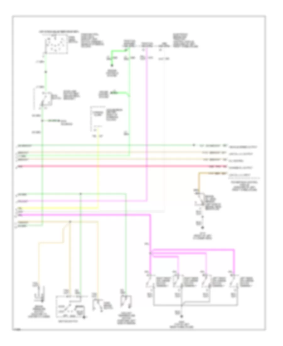
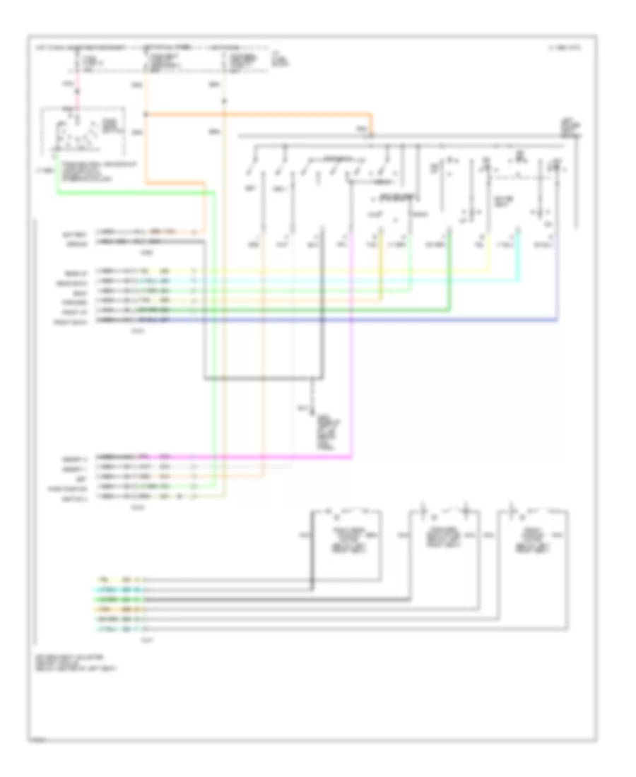
AIR CONDITIONING
Air Conditioning Wiring Diagrams for Cadillac Fleetwood 1995
 https://portal-diagnostov.com/license.html
Automotive Electricians Portal FZCO
Automotive Electricians Portal FZCO
https://portal-diagnostov.com/license.html
https://portal-diagnostov.com/license.html
Automotive Electricians Portal FZCO
Automotive Electricians Portal FZCO
List of elements for Air Conditioning Wiring Diagrams for Cadillac Fleetwood 1995:
- (behind compressor)
- (behind right headlamp
- (front of left
- (front of left cylinder head)
- +5v
- 40a
- A/c comp fuse 10a
- A/c compressor clutch
- A/c compressor clutch diode
- A/c compressor pressure cycling switch (right rear of engine compartment, on accumulator)
- A/c compressor relay (in underhood electrical center)
- A/c on signal
- A/c refrigerant pressure sensor
- A/c request
- Air mix motor (attached to left side of plenum)
- Attached to radiator support)
- Batt
- Battery
- Blower motor
- Blower motor control module (right i/p)
- Blw ctrl
- Blw motor fdbk
- Blw spd ctrl
- C1 a
- C10
- C11
- C12
- C13
- C14
- C15
- C16
- Ctrl sig
- Cylinder head)
- D10
- D11
- D12
- D13
- D14
- D15
- D16
- Data link connector (right of steering column)
- Def sol signal
- Dlc data link
- E/m signal
- Electric act drive
- G109
- G112
- G200 (left kickpad)
- Gen fuse 10a
- Ground
- Heater-a/c control
- Hot at all times
- Hot in run
- Htr sol signal
- Hvac bat fuse 10a
- Hvac ign fuse 10a
- Hvac mdl fuse 25a
- I/p fuse block
- Ignition
- Illumination
- Inside air temp
- Inside air temperature sensor (above glove box)
- Instrument cluster
- Interior lights system
- Logic
- Lower sol signal
- Nca
- Outside air temp
- Outside air temperature sensor (on hood latch support)
- Power steering pressure switch (near power steering unit)
- Powertrain control module (behind right side of i/p)
- Pressure switch input
- Primary clg fan maxi fuse
- Primary coolant fan motor (base and v03)
- Primary engine coolant fan relay (underhood electrical center) (base and v03)
- Rear defog
- Rear defogger system
- Recirc sol signal
- Red
- Relay control
- Second- ary clg fan maxi fuse
- Secondary coolant fan motor
- Secondary engine coolant fan relay (underhood electrical center)
- Sensor ground
- Sensor input
- Sun sensor input
- Sunload temperature sensor (top center of i/p)
- Tan
- Temp valve fdbk
- Underhood electrical center
- Upper sol signal
- Vacuum/electric solenoid (near center of i/p)
- Vf dim signal
ANTI-LOCK BRAKES
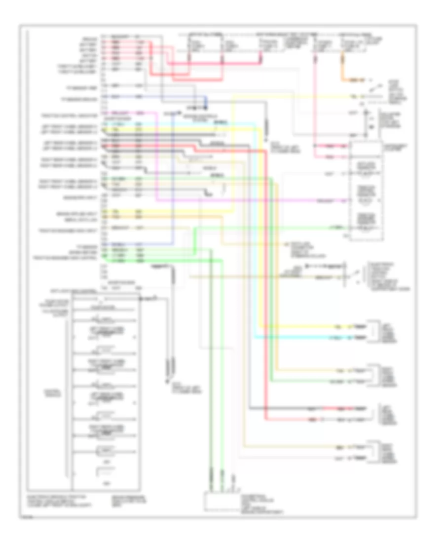
Anti-lock Brake Wiring Diagrams for Cadillac Fleetwood 1995
List of elements for Anti-lock Brake Wiring Diagrams for Cadillac Fleetwood 1995:
- (on top of brake pedal)
- Adjuster motor (top left of engine)
- Anti-lock indic control
- Antilock indicator
- Asv
- Battery
- Brake pressure modulator valve (bpm)
- Control signals
- Data link connector (right of steering column)
- Electronic
- Electronic brake & traction control module (ebtcm) (lower left front of eng compt)
- Engine controls system
- Engine rpm input
- G110 (front of left cylinder head)
- G203 (at right kick panel)
- Ground
- Hot at all times
- Hot in run, bulb test or start
- I/p fuse block
- I/p indic fuse 11 10a
- Ignition
- Instrument cluster
- Left front wheel sensor hi
- Left front wheel sensor lo
- Left front wheel speed sensor
- Left front wheel valve solenoids
- Left rear wheel sensor hi
- Left rear wheel sensor lo
- Left rear wheel speed sensor
- Left rear wheel valve solenoids
- Maxi fuse 5 50a
- Maxi fuse 6 20a
- Nca
- Nca 814
- Out
- Pcm/ign fuse 15 10a
- Pnk
- Powertrain control module (pcm) (left side of engine compartment)
- Pump motor
- Pump motor power output
- Red
- Right front wheel sensor hi
- Right front wheel sensor lo
- Right front wheel speed sensor
- Right front wheel valve solenoids
- Right rear wheel sensor hi
- Right rear wheel sensor lo
- Right rear wheel speed sensor
- Right rear wheel valve solenoids
- Serial data link
- Shield
- Shorting bar
- Spark retard
- Stop lamp switch
- Stop lts fuse 38 20a
- Tan
- Throttle relaxer +
- Throttle relaxer -
- Tp sensor
- Tp sensor ground
- Tp sensor vref
- Traction control indicator
- Traction control switch (right side of i/p, behind i/p compartment door)
- Traction engaged indic control
- Traction engaged indic input
- Traction engaged indicator
- Underhood electrical center
- Usv
- Valve power output
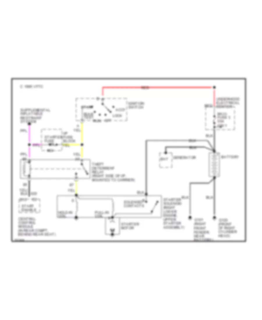
ANTI-THEFT
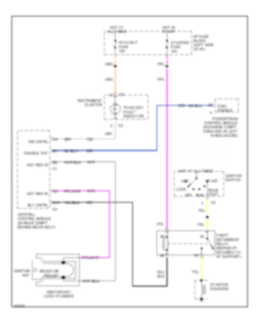
Pass-Key Wiring Diagram for Cadillac Fleetwood 1995
List of elements for Pass-Key Wiring Diagram for Cadillac Fleetwood 1995:
- "pass key fault" indicator
- Acc
- Bulb test
- Central control module (in rear compt, behind rear seat)
- D13
- Enable out
- Fuel enable
- Hot at all times
- Hot in start
- Hvac bat fuse 10a
- I/p fuse block (left side of i/p)
- Ignition key
- Ignition key lock cylinder
- Ignition switch
- Ind cntrl
- Instrument cluster
- Key res in
- Lock
- Off
- Powertrain control module (in engine compt, forward of left wheelhouse)
- Resistor pellet
- Rly cntrl
- Run
- Start
- Starter fuse 10a
- Starter solenoid
- Theft deterrent relay (behind i/p, secured to i/p support)
BODY COMPUTER
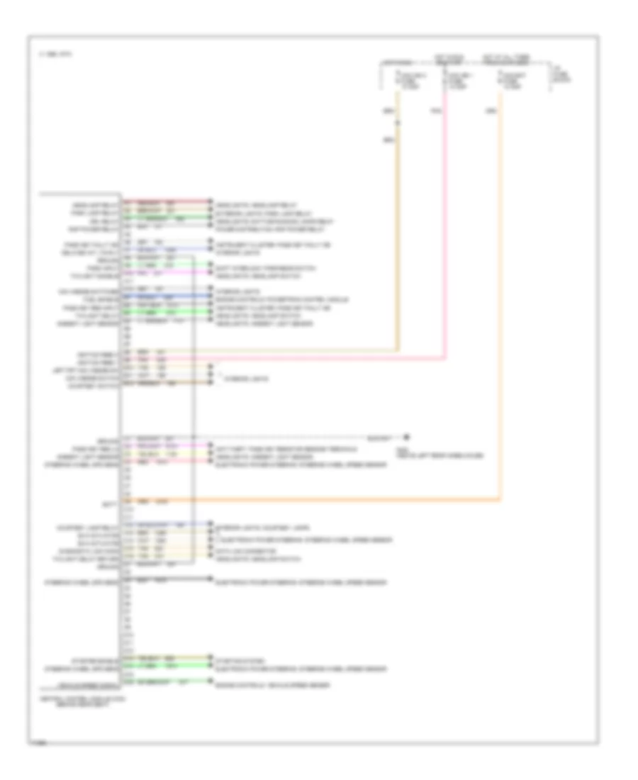
Body Computer Wiring Diagrams for Cadillac Fleetwood 1995
List of elements for Body Computer Wiring Diagrams for Cadillac Fleetwood 1995:
- 1995 vftc c
- A1 headlamp relay
- A10 twilight disable
- A11
- A12 mini wedge switches
- A2 park lamp relay
- A3 drl relay
- A4 rap power relay
- A6 pass key fault ind
- A7 delayed int lts rly
- A8 ground
- A9 park input
- Anti-theft: pass key resistor sensing terminals
- B1 fuel enable
- B10 left frt mini wedge sw
- B11 mini wedge switch
- B12 courtesy switch
- B2 pass key res input
- B3 twilight delay
- B4 ambient light sensor
- B8 ignition feed 3
- B9 ignition feed 1
- C1 ground
- C10
- C11
- C12 courtesy lamp relay
- C13 evo actuator
- C14 evo actuator
- C15 diagnostic link conn
- C16 twilight delay return
- C2 pass key res lo
- C3 ambient light sensor
- C4 steering wheel spd sens
- C9 batt
- Ccm bat fuse 10 amp
- Ccm ign 1 fuse 10 amp
- Ccm ign 3 fuse 10 amp
- Central control module (ccm) (behind rear seat)
- D1 ground
- D10
- D11
- D12
- D13 starter enable
- D14 steering wheel spd sens
- D15
- D16 vehicle speed signal
- D3 steering wheel spd sens
- Data link connector
- Electronic power steering: steering wheel speed sensor
- Engine controls: powertrain control module
- Engine controls: vehicle speed sensor
- Exterior lights: park lamp relay
- G402 (above left rear wheelhouse)
- Headlights: ambient light sensor
- Headlights: daytime running lamps relay
- Headlights: headlamp relay
- Headlights: headlamp switch
- Hot at all times from maxifuse 2
- Hot in run
- Hot in run or start
- I/p fuse block
- Instrument cluster: pass key fault ind
- Interior lights
- Interior lights: courtesy lamps
- Pnk
- Power distribution: rap power relay
- Red
- Shift interlock: park/rear switch
- Starting system
- Tan
COMPUTER DATA LINES
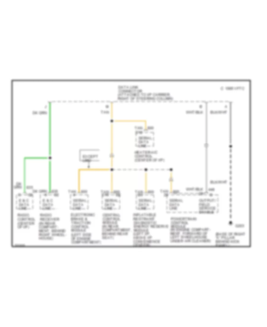
Data Link Connector Wiring Diagram for Cadillac Fleetwood 1995
List of elements for Data Link Connector Wiring Diagram for Cadillac Fleetwood 1995:
- (base of right "a" pillar behind kick panel)
- C 1995 vftc
- Central control module (in rear compartment, behind rear seat)
- Data link connector (attached to i/p carrier, right of steering column)
- E & c data line
- Electronic brake & traction control module (left side of engine compartment)
- Except limo
- G203
- Heater-a/c control (center of i/p)
- Inflatable restraint diagnostic energy reserve module (left i/p, above i/p convenience center)
- Output/ field service enable
- Powertrain control module (in engine compart- ment, forward of left wheelhouse under air cleaner)
- Radio control (center of i/p)
- Radio receiver (in rear compart- ment, behind right wheel- house)
- Serial data line
- Tan
- Tan b3
- Tan c15
- Tan d12
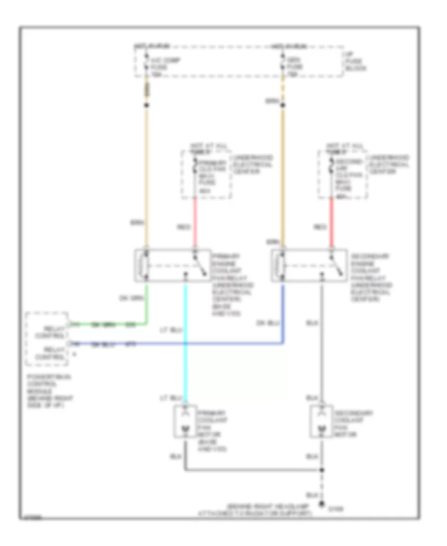
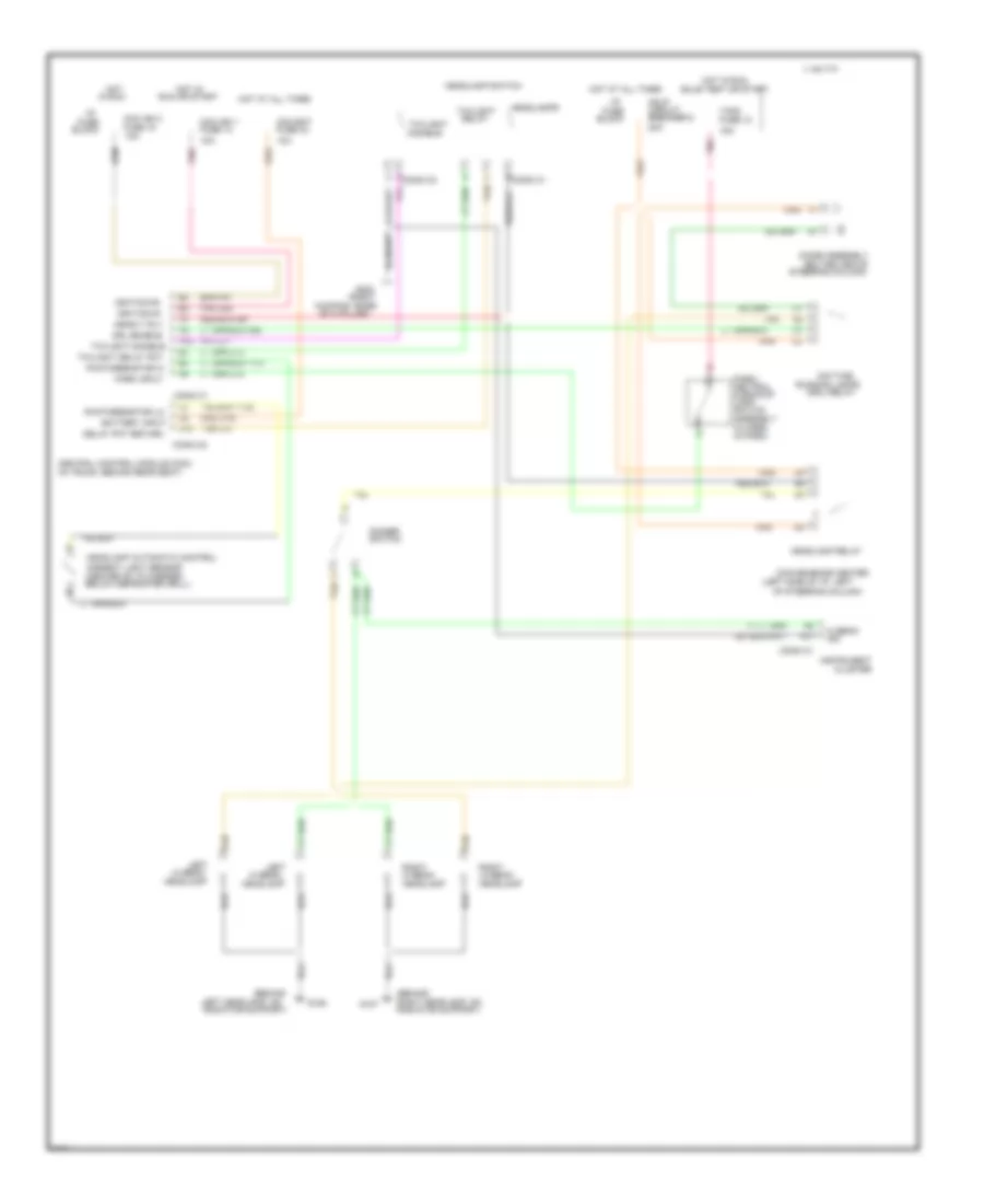
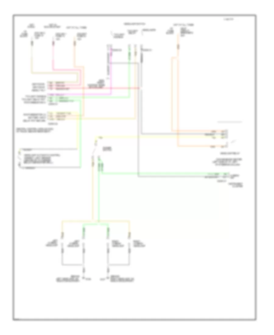
COOLING FAN
Cooling Fan Wiring Diagram for Cadillac Fleetwood 1995
List of elements for Cooling Fan Wiring Diagram for Cadillac Fleetwood 1995:
- (behind right headlamp
- 40a
- A/c comp fuse 10a
- Attached to radiator support)
- G109
- Gen fuse 10a
- Hot at all times
- Hot in run
- I/p fuse block
- Powertrain control module (behind right side of i/p)
- Primary clg fan maxi fuse
- Primary coolant fan motor (base and v03)
- Primary engine coolant fan relay (underhood electrical center) (base and v03)
- Red
- Relay control
- Second- ary clg fan maxi fuse
- Secondary coolant fan motor
- Secondary engine coolant fan relay (underhood electrical center)
- Underhood electrical center
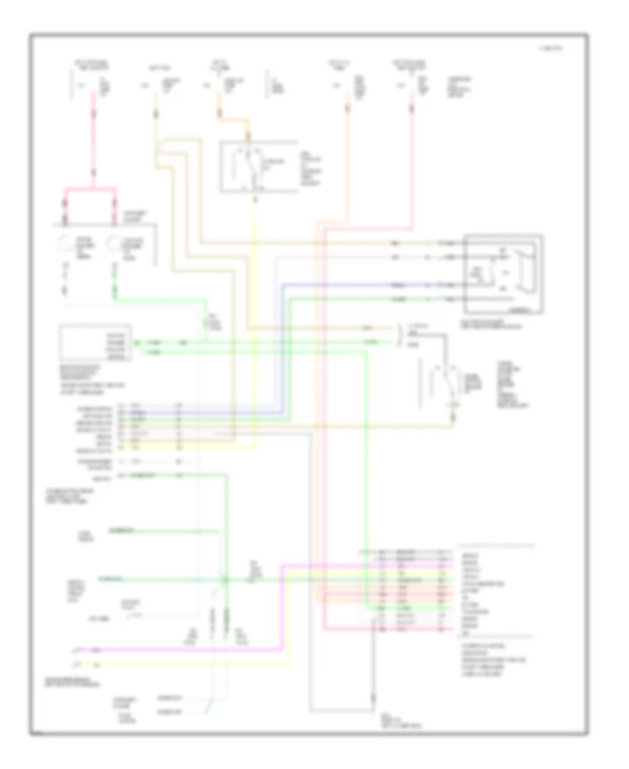
CRUISE CONTROL
Cruise Control Wiring Diagram for Cadillac Fleetwood 1995
List of elements for Cruise Control Wiring Diagram for Cadillac Fleetwood 1995:
- "cruise
- "cruise engaged"
- "traction
- #11
- #13
- #15
- #18
- #44
- (ccm)
- (engine compartment, forward
- (front of
- (green)
- (left rear of transmission)
- (left side of steering column)
- (mounted to left
- (not used)
- (on brake
- (u/h)
- 10a
- 15a
- 20a
- 4000 pulses per mile
- A18
- A31
- A32
- All times
- Assembly
- B/h
- B/h conn
- B11
- B13
- B15
- B28
- B30
- B31
- Base
- Battery
- Block
- Bracket)
- Brake cut out #1
- Brake cut out #2
- Btsi
- C 1995 vftc
- C11
- C32
- Ccm ign 3
- Center
- Central
- Chime
- Cluster
- Clutch/
- Coast
- Conn
- Control
- Converter
- Cruise
- Cruise control module
- Cruise on/off sig
- Cruise sw
- Electrical
- Electronic brake &
- Engaged
- Engaged"
- Front wheel house)
- Fuel
- Fuse
- G110
- Ground
- Hot at
- Hot at all
- Hot in run
- Hot in run, bulb
- Hot in run, bulb
- I/p
- Ign
- Ignition
- Ind
- Ind control
- Indic
- Indicator
- Instrument
- Left cylinder head)
- Limo
- Module
- Module (ebtcm)
- Module (pcm)
- Multi/function lever
- Nca
- Of left wheelhouse
- Of left wheelhouse)
- Off
- Pcm/
- Pedal
- Pedal bracket)
- Pin b3
- Pin b4
- Pin e2
- Pin f8
- Pin h2
- Pnk
- Powertrain control
- Pump
- R/a
- Radio
- Release
- Resume/accel sig
- Set/
- Set/coast sig
- Stop lts
- Stoplamp
- Test or start
- Times
- Torque
- Trac eng sig
- Traction
- Traction control
- Under air cleaner)
- Underhood
- Vehicle speed sensor
- Vss in/hi
- Vss in/lo
- Vss input
- W/ v4f/v4u
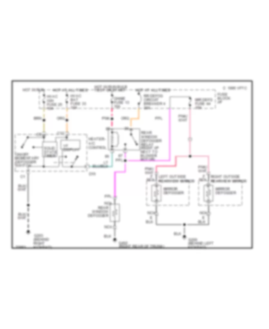
DEFOGGERS
Defogger Wiring Diagram for Cadillac Fleetwood 1995
List of elements for Defogger Wiring Diagram for Cadillac Fleetwood 1995:
- C 1995 vftc
- C12
- Chime fuse 13 10a
- D15
- F nca rearview mirror
- Fuse block: i/p
- G200 (behind left kickpad)
- G203 (behind right kickpad)
- G402 (right rear of trunk)
- Heater- a/c control
- Hot at all times
- Hot in run
- Hot in run bulb test or start
- Hvac bat fuse 33 10a
- Hvac ign fuse 25 10a
- Left outside
- Mir defg fuse 44 10a
- Mirror defogger
- Nca
- On/off momentary defogger switch
- Pnk
- Rear window defogger
- Rear window defogger relay (right i/p next to blower motor)
- Right outside
- Rr defog circuit breaker 4 30a
- Solid state timer
- Vf display
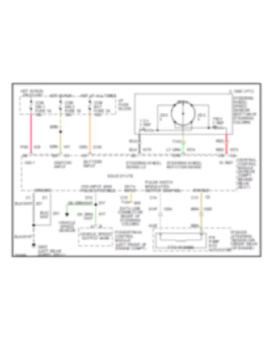
ELECTRONIC POWER STEERING
Electronic Power Steering Wiring Diagram for Cadillac Fleetwood 1995
List of elements for Electronic Power Steering Wiring Diagram for Cadillac Fleetwood 1995:
- 1.3 k v ref lo
- 29.6 k
- 5v ref
- 7 to 15 ohms
- 790 k v ref hi
- Battery input
- C 1995 vftc
- C13
- C14
- C15
- Ccm bat fuse 34 10a
- Ccm ign 1 fuse 14 10a
- Ccm ign 3 fuse 18 10a
- Central control module (in rear compt, behind rear seat)
- D14
- D16
- Data input
- Data link connector (right of steering column)
- Enable
- G402 (left rear wheel well)
- Ground
- Hot at all times
- Hot in run
- Hot in run or start
- I/p fuse block
- Ign 1
- Ignition input
- Orn
- P/s pump evo actuator
- Pnk
- Power steering reservoir (right rear of engine)
- Powertrain control module (left front of engine compt)
- Pulse width modulated output control
- Red
- Solid state
- Steering wheel rotation sense
- Steering wheel sense lo
- Steering wheel speed sensor (bottom of steering column)
- Tan
- Vehicle speed output 4k/mi
- Vehicle speed sensor
- Vss input 4000 pulses per mile
ELECTRONIC SUSPENSION
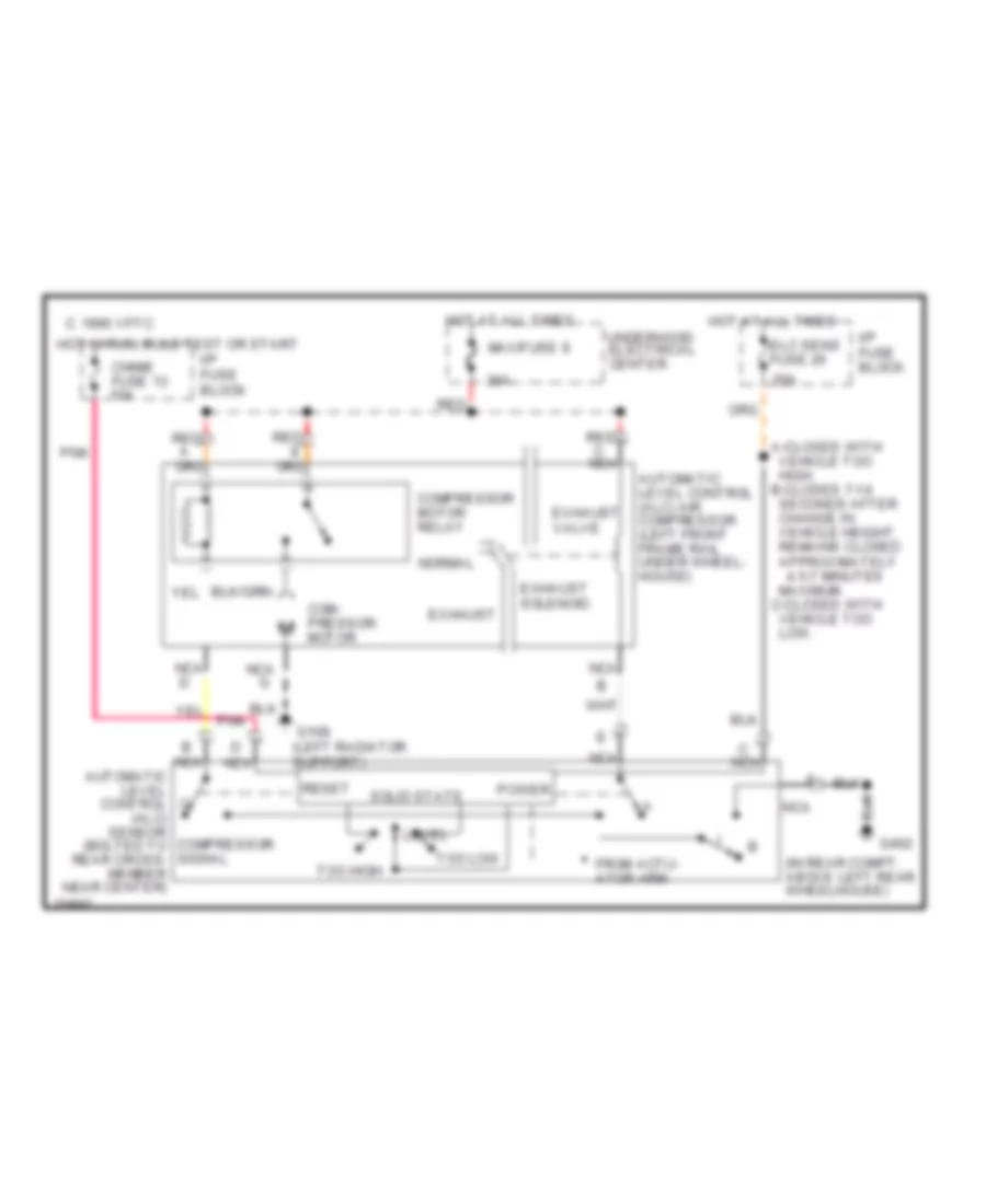
Electronic Level Control for Cadillac Fleetwood 1995
List of elements for Electronic Level Control for Cadillac Fleetwood 1995:
- maximum. c-closes with vehicle too low.
- (in rear compt, above left rear wheelhouse)
- 20a
- 30a
- 4.5-7 minutes
- A-closes with vehicle too high. b-closes 7-14 seconds after change in vehicle height. remains closed approximately
- Automatic level control (alc) air compressor (left front frame rail under wheel- house)
- C 1995 vftc
- Chime fuse 13 10a
- Com- pressor motor
- Compressor motor relay
- Elc sens fuse 26
- Exhaust
- Exhaust solenoid
- Exhaust valve
- From actu- ator arm
- G108 (left radiator support)
- G402
- Hot at all times
- Hot in run, bulb test or start
- I/p fuse block
- Level
- Maxifuse 9
- Nca
- Nca automatic level control (alc) sensor compressor (bolted to signal rear cross- member near center)
- Normal
- Pnk
- Power
- Red
- Reset
- Solid state
- Too high
- Too low
- Underhood electrical center
ENGINE PERFORMANCE
5.7L
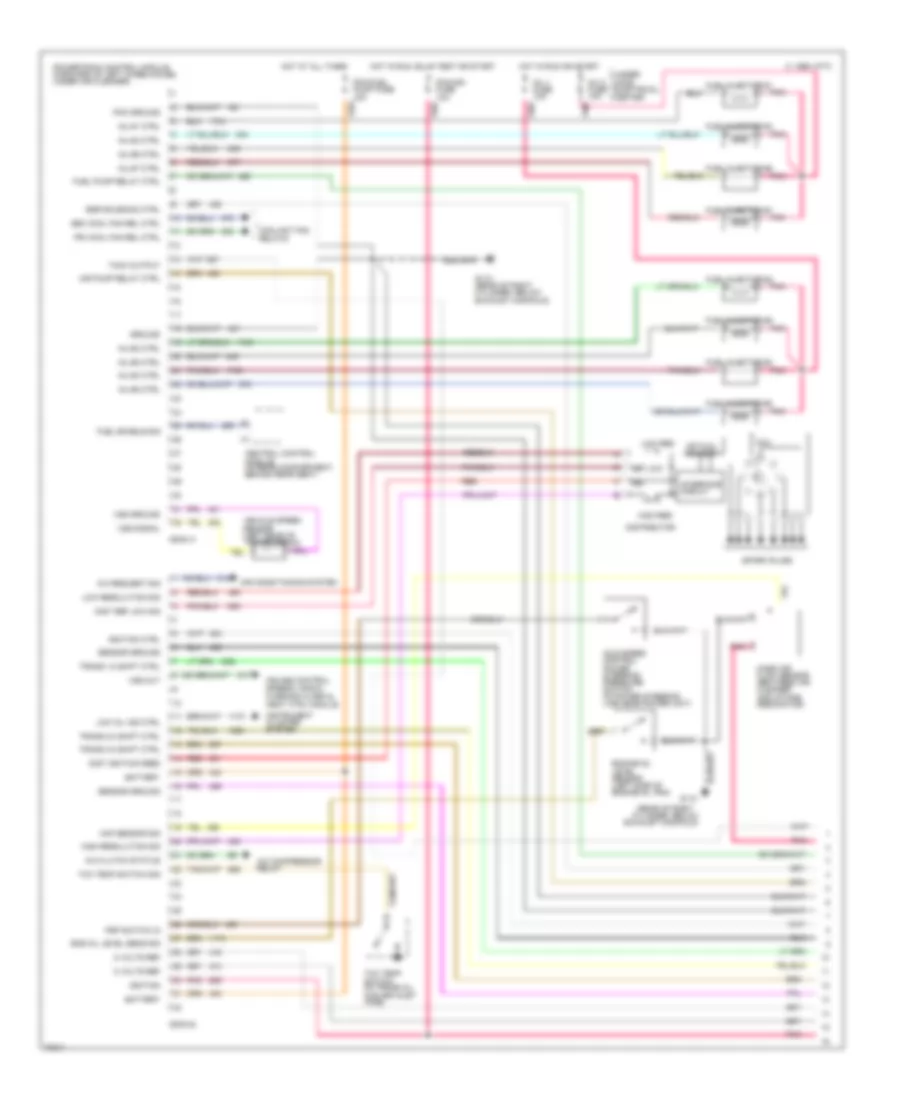
5.7L (VIN P), Engine Performance Wiring Diagrams (1 of 3) for Cadillac Fleetwood 1995
List of elements for 5.7L (VIN P), Engine Performance Wiring Diagrams (1 of 3) for Cadillac Fleetwood 1995:
- high res
- (rear of right cylinder, below
- 5 volts ref
- A/c clutch status
- A/c compressor relay
- A/c request sig
- Air conditioning system
- Air pump relay ctrl
- Battery
- C 1995 vftc
- Central control module (in rear compartment, behind rear seat)
- Coil
- Conn a
- Conn b
- Coolant fan relays
- Cruise control, speedo, radio, warning alarm & cent ctrl module
- Dist ignition feed
- Dist ref low sig
- Distributor
- Egr solenoid ctrl
- Eng oil level sens sig
- Engine oil level sensor (left side of engine oil pan)
- Exhaust manifold)
- Fuel enable sig
- Fuel injector #1
- Fuel injector #2
- Fuel injector #3
- Fuel injector #4
- Fuel injector #5
- Fuel injector #6
- Fuel injector #7
- Fuel injector #8
- Fuel pump relay ctrl
- G110
- G110 (rear of right cylinder, below exhaust manifold)
- Ground
- High resolution sig
- Hot at all times
- Hot in run or start
- Hot in run, bulb test or start
- Idle speed control power steering pressure switch (in power steering line near power unit)
- Ign
- Ignition
- Ignition ctrl
- Inj #1 ctrl
- Inj #2 ctrl
- Inj #3 ctrl
- Inj #4 ctrl
- Inj #5 ctrl
- Inj #6 ctrl
- Inj #7 ctrl
- Inj #8 ctrl
- Inj 1 fuse 10a
- Inj 2 fuse 10a
- Instrument cluster system
- Interface circuit
- Low oil ind ctrl
- Low res
- Low resolution sig
- Maf sensor sig
- Mass air flow sensor (between air cleaner and intake resonator)
- Optical sensor
- Pcm ground
- Pcm/fuel pump fuse 15a
- Pcm/ign fuse 10a
- Pnk
- Powertrain control module (forward of left wheelhouse, under air cleaner)
- Pri cool fan rel ctrl
- Psp switch in
- Red
- Ref low
- Sec cool fan rel ctrl
- Sensor ground
- Spark plugs
- Tach output
- Tcc temp switch (in trans oil cooler inlet pipe)
- Tcc temp switch sig
- Trans 1-2 shift ctrl
- Trans 2-3 shift ctrl
- Trans 3-2 shift ctrl
- Under- hood electrical center
- Vehicle speed sensor (left rear of transmission)
- Vss ground
- Vss out
- Vss signal
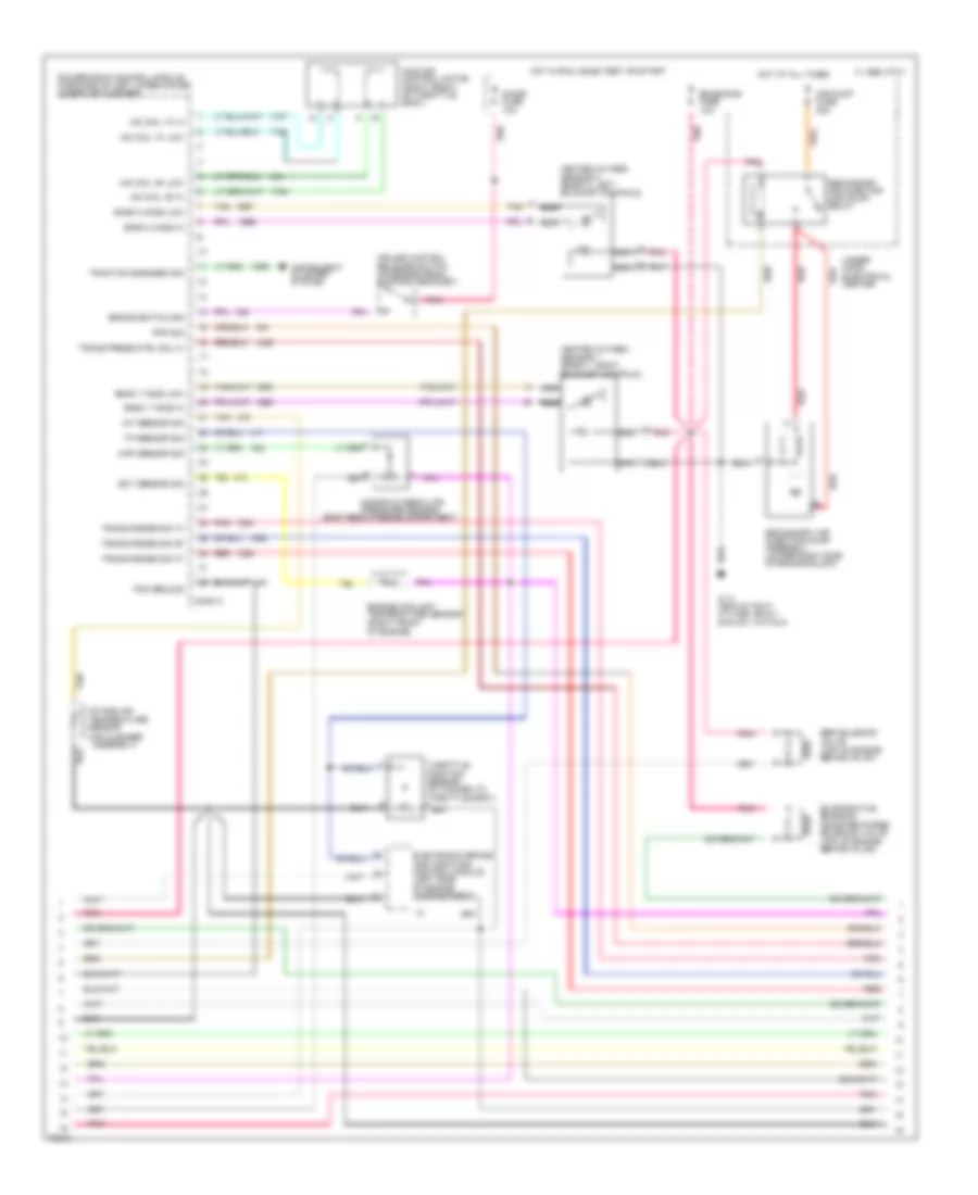
5.7L (VIN P), Engine Performance Wiring Diagrams (2 of 3) for Cadillac Fleetwood 1995
List of elements for 5.7L (VIN P), Engine Performance Wiring Diagrams (2 of 3) for Cadillac Fleetwood 1995:
- (right rear of engine compartment)
- Air pump fuse 20a
- Bank 1 h02s low
- Bank 1 ho2s hi
- Bank 2 ho2s hi
- Bank 2 ho2s low
- Brake switch sig
- C 1995 vftc
- Chime fuse 10a
- Conn c
- Cruise control release switch (on brake pedal support bracket)
- D pnk
- Ect sensor sig
- Egr solenoid valve (top of engine behind inj #7)
- Electronic brake and traction control module (left side of engine compartment)
- Emissions fuse 10a
- Engine coolant temperature sensor (right front of engine)
- Evaporative emission canister purge solenoid valve (top of engine behind inj #4)
- G110 (rear of right cylinder, below exhaust manifold)
- Heated oxygen sensor 1 (bank 1, right exhaust manifold)
- Heated oxygen sensor 2 (bank 2, left exhaust manifold)
- Hot at all times
- Hot in run, bulb test or start
- Iac coil "a" hi
- Iac coil "a" low
- Iac coil "b" hi
- Iac coil "b" low
- Iat sensor sig
- Idle air control motor (right front of throttle body)
- Instrument cluster system
- Intake air temperature sensor (air cleaner assembly)
- Manifold absolute pressure sensor
- Map sensor sig
- Nca
- Pcm ground
- Pnk
- Pnp sig
- Powertrain control module (forward of left wheelhouse, under air cleaner)
- Red
- Red a
- Red b
- Secondary air injection pump assembly (lower right side of engine block)
- Secondary air injector (air) pump relay
- Tan
- Throttle position sensor (attached to throttle body) a
- Tp sensor sig
- Traction engaged sig
- Trans press ctrl sol hi
- Trans range sig "a"
- Trans range sig "b"
- Trans range sig "c"
- Under- hood electrical center
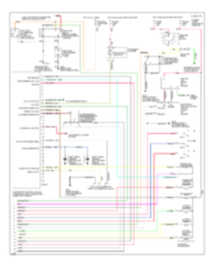
5.7L (VIN P), Engine Performance Wiring Diagrams (3 of 3) for Cadillac Fleetwood 1995
List of elements for 5.7L (VIN P), Engine Performance Wiring Diagrams (3 of 3) for Cadillac Fleetwood 1995:
- (rear of right cylinder, below exhaust manifold)
- 1-2 shift solenoid
- 2-3 shift solenoid
- 3-2 ctrl solenoid (pwm)
- A/c clutch ctrl
- A/c compressor relay
- A/c press sensor sig
- A/c refrigerant pressure sensor (in hi pressure line above right wheelhouse)
- Automatic transmission
- C 1995 vftc
- Canister purge ctrl
- Change oil ind ctrl
- Chime fuse 10a
- Coil driver
- Conn d
- Data link connector (right of steering column)
- Electronic ignition control module (front of engine)
- Exterior lights system (backup lights circuit)
- Forward gear switch
- Fuel pump priming connector (near a/c accumulator)
- Fuel pump relay (behind under- hood electrical center)
- Fuel pump/ level sender (in fuel tank)
- Fuel pump/ oil pressure switch (lower left side of engine)
- G110
- G110 (rear of right cylinder, below exhaust manifold)
- G203 (base of right "a" pillar, behind kick panel)
- G402 (above left rear wheelhouse)
- Ground
- Hot at all times
- Hot in run, bulb test or start
- I/p indc fuse 10a
- Ign
- Ign ctrl
- Ignition
- Ignition coil (front of engine)
- Instrument cluster
- Instrument cluster system
- Isolation diode
- Knock sensor sig
- Left knock sensor (bottom left side of engine block)
- Malfunction indicator
- Mil ctrl
- Output/field serv enbl
- Park/neutral position relay (convenience center)
- Pcm ground
- Pcm/fuel pump fuse 15a
- Pcm/ign fuse 10a
- Pnk
- Powertrain control module (forward of left wheelhouse, under air cleaner)
- Pressure control solenoid
- Red
- Right knock sensor (bottom right side of engine block)
- Serial data
- Sw a
- Sw b
- Sw c
- Tach- ometer filter
- Tan
- Tan m
- Tcc solenoid
- Trans fluid temp sensor
- Trans fluid temp sig
- Trans press ctrl low
- Trans tcc ctrl
- Under- hood electrical center
EXTERIOR LIGHTS
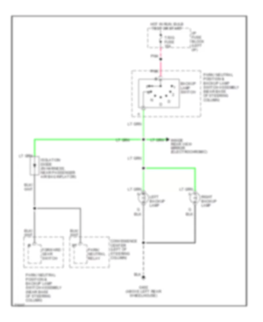
Back-up Lamps Wiring Diagram for Cadillac Fleetwood 1995
List of elements for Back-up Lamps Wiring Diagram for Cadillac Fleetwood 1995:
- Backup lamp switch
- Convenience center (left of steering column)
- Forward gear switch
- G402 (above left rear wheelhouse)
- Hot in run, bulb test or start
- I/p fuse block (left i/p)
- Inside rear view mirror (electrochromic)
- Isolation diode (in harness, near passenger air bag inflator)
- Left backup lamp
- Park/ neutral position & backup lamp switch assembly (near base of steering column)
- Park/ neutral relay
- Pnk
- Right backup lamp
- T/sig fuse 15a
Exterior Light Wiring Diagram for Cadillac Fleetwood 1995
List of elements for Exterior Light Wiring Diagram for Cadillac Fleetwood 1995:
- A right front marker lamp b
- A10
- Auxiliary wire (use as needed)
- Brake/traction control module
- C210
- C211
- Center high mounted stop lamps
- Central control module
- Cornering lamp switch
- Cornr lts fuse 10a
- Cruise control module
- Deterrent module
- Door lock
- Electric turn signal flasher (left i/p)
- Electronic
- G108 (upper left radiator support)
- G109 (upper right radiator support)
- G200 (left kick panel)
- G203 (right kick panel)
- G402 (above left rear wheelhousing)
- Hazard
- Hazard lamp flasher (left i/p)
- Hazard switch
- Hazrd lts fuse 20a
- Head
- Headlamp switch
- Hot at all times
- Hot in run, bulb test or start
- I/p fuse block (left i/p)
- Instrument cluster
- Left
- Left corn- ering lamp
- Left front marker lamp
- Left front park/ turn lamps
- Left rear marker lamp
- License lamp
- Nca
- Normal
- Not used
- Off
- Optional
- Park
- Park lamp relay (left of steering column, in convenience center)
- Park lts fuse 20a
- Pnk
- Receiver/theft
- Remote control
- Remote control door lock receiver/theft deterrent module
- Right
- Right corn- ering lamp
- Right front park/ turn lamps
- Right rear marker light
- Right tail/ stop lamp
- Right tail/ stop/ turn lamps
- Stop lamp switch (attached to brake pedal bracket)
- Stop lts fuse 20a
- T/sig fuse 15a
- Tail lts fuse 10a
- Timer
- Trailer connector (optional)
- Turn switch
- Turn/ hazard- switch assembly
- Vacuum fluorescent indicators
- Warning alarm
GROUND DISTRIBUTION
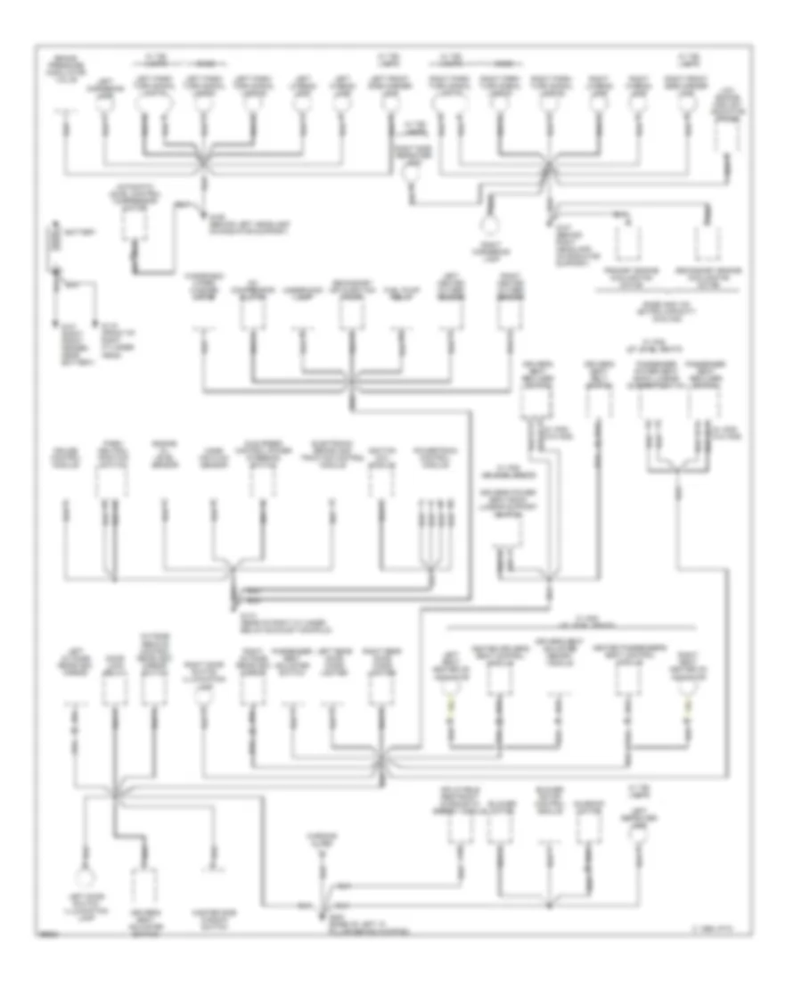
Ground Distribution Wiring Diagram (1 of 2) for Cadillac Fleetwood 1995
List of elements for Ground Distribution Wiring Diagram (1 of 2) for Cadillac Fleetwood 1995:
- A/c compressor clutch
- A10
- Automatic level control compressor motor
- Base
- Base and v03 (extra capacity cooling)
- Battery
- Blower motor
- Blower motor control module
- Brake pressure modulator valve
- C 1995 vftc
- C e
- Cruise control module
- Door lock relay
- Driver's power seat back lumbar support switch
- Driver's seat adjuster memory module
- Driver's seat adjuster switch
- Driver's seat belt switch
- Driver's seat recliner switch
- Electronic brake and traction control module
- Engine oil level sensor
- F (w/ am5) b (w/o am5)
- Fuel pump relay
- G101 (right front fender, near battery)
- G106 (behind left headlamp on radiator support)
- G107 (behind right headlamp, on radiator support)
- G110 (rear of right cylinder below exhaust manifold)
- G119 (front of right cylinder head)
- G200 (base of left "a" pillar behind kickpad)
- Heated driver's seat control module
- Heated passenger's seat control module
- Idle speed control power steering switch
- Ignition coil module
- Inflatable restraint diagnostic energy module
- Left cornering lamp
- Left door switch illumination lamp
- Left front side marker lamp
- Left heated oxygen sensor
- Left hi-beam lamp
- Left lo-beam lamp
- Left outside rearview mirror
- Left park/ turn signal lamp #1
- Left park/ turn signal lamp #2
- Left rear door cigar lighter
- Left repeater lamp
- Left seat heater on indicator
- Low engine coolant indicator probe
- Mass air flow sensor
- Master side window switch
- Outside remote control rearview mirror switch
- Park/ neutral position switch
- Passenger power seat back lumbar support switch
- Passenger seat adjuster switch
- Passenger seat recliner switch
- Powertrain control module
- Primary engine cooling fan motor
- Right cornering lamp
- Right door switch illumination lamp
- Right front side marker lamp
- Right heated oxygen sensor
- Right hi-beam lamp
- Right lo-beam lamp
- Right outside rearview mirror
- Right park/ turn signal lamp #1
- Right park/ turn signal lamp #2
- Right rear door cigar lighter
- Right seat heater on indicator
- Right side repeater lamp
- Secondary air injection pump
- Secondary engine cooling fan motor
- Sunroof motor
- Underhood lamp
- W/ am5 up level seats
- W/ t90 lamps
- Warning alarm
- Windshield wiper/ washer motor
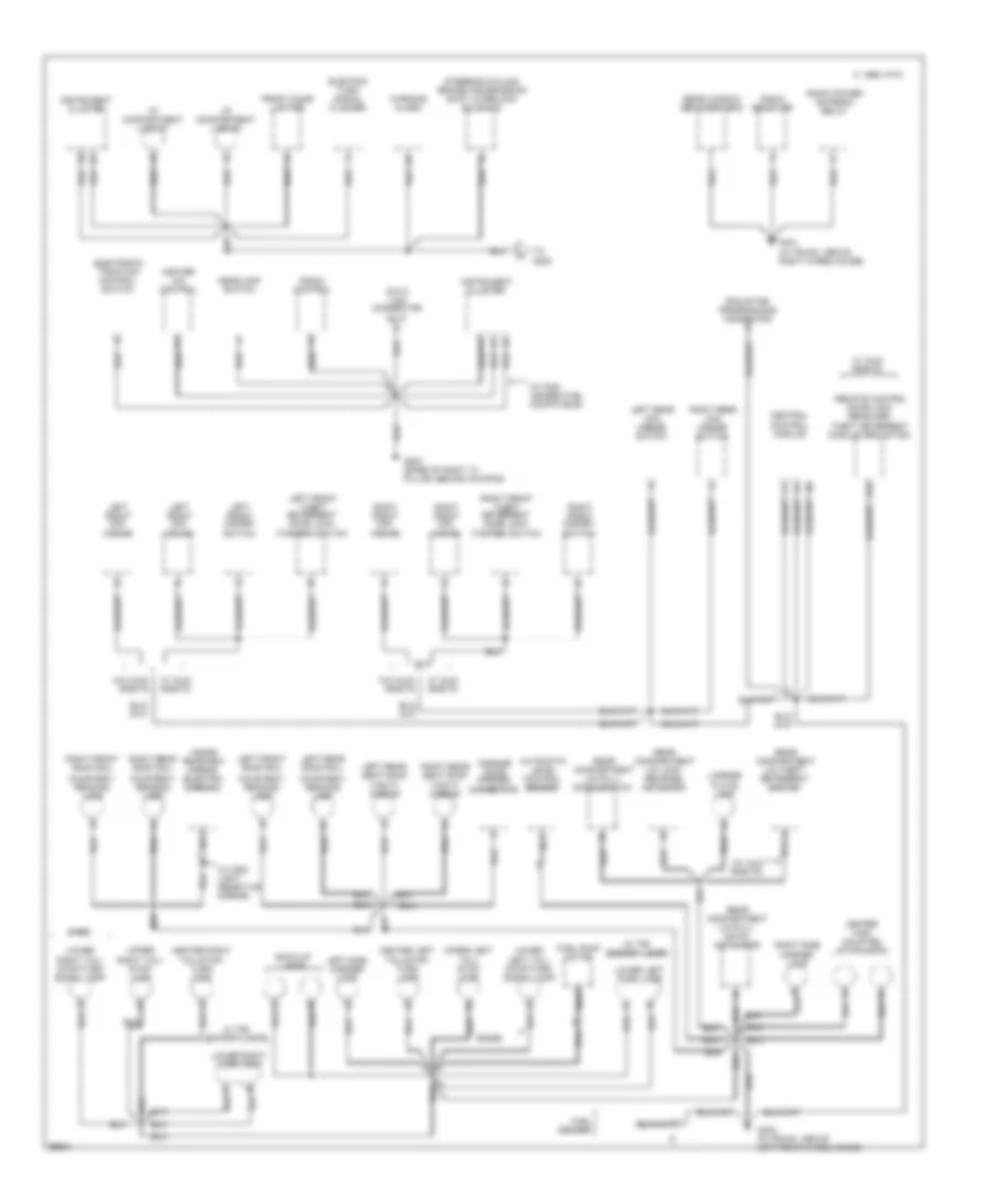
Ground Distribution Wiring Diagram (2 of 2) for Cadillac Fleetwood 1995
List of elements for Ground Distribution Wiring Diagram (2 of 2) for Cadillac Fleetwood 1995:
- (base)
- (w/ auo rke/td)
- (w/ dd8 light sensitive mirror)
- (w/ nm8 leaded fuel compatible)
- A11
- Automatic level control sensor
- Back-up lamps
- Base
- C 1995 vftc
- Center high mounted stop lamps
- Center left
- Center right
- Central control module
- Courtesy/ reading lamp
- D16
- Data link connector (dlc)
- Electric turn signal flasher
- Electronic traction control switch
- Front cigar lighter
- Fuel pump motor
- Fuel sender
- G203 (base of right "a" pillar, behind kickpad)
- G401 (in trunk, above right wheelhouse)
- G402 (in trunk, above left rear wheelhouse)
- Garage door opener connector
- Headlamp switch
- Heater a/c control
- I/p compartment lamp #1
- I/p compartment lamp #2
- Inside rearview mirror (electro chromic)
- Instrument cluster
- Left front disarm switch
- Left front mini wedge
- Left front roof rail
- Left front theft deterrent door lock (tamper) switch
- Left rear mini wedge switch
- Left rear roof rail
- Left rear seat roof
- Left side marker lamp
- Left tail/ stop/turn signal lamp
- License
- Lower
- Lower left turn lamp
- Lower right turn lamp
- Marker lamp
- Nca
- Plate lamp
- Radio control
- Radio power antenna relay
- Radio receiver
- Rcdlr/tdm programming connector a
- Rear compartment lid lock release actuator
- Rear compartment lid pull- down activator
- Rear compartment lid pull- down switch
- Rear compartment lid theft deterrent switch
- Rear window defogger grid
- Remote control door lock receiver/ theft deterrent module (rcdlr/tdm)
- Right front disarm switch
- Right front mini wedge
- Right front roof rail
- Right front theft deterrent door lock (tamper) switch
- Right rear mini wedge switch
- Right rear roof rail
- Right rear seat roof
- Right side
- Right tail/ stop lamp
- Right tail/ stop/turn signal lamp
- Steering column brake/transmission shift interlock solenoid
- Tail/ stop lamp
- Tail/stop/ turn lamp
- To g200
- Upper
- Upper left
- Vanity mirror
- W/ auo/ rke/td
- W/ t90 export lamps
- W/o auo/ rke/td
- Warning alarm
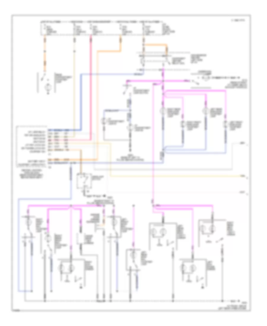
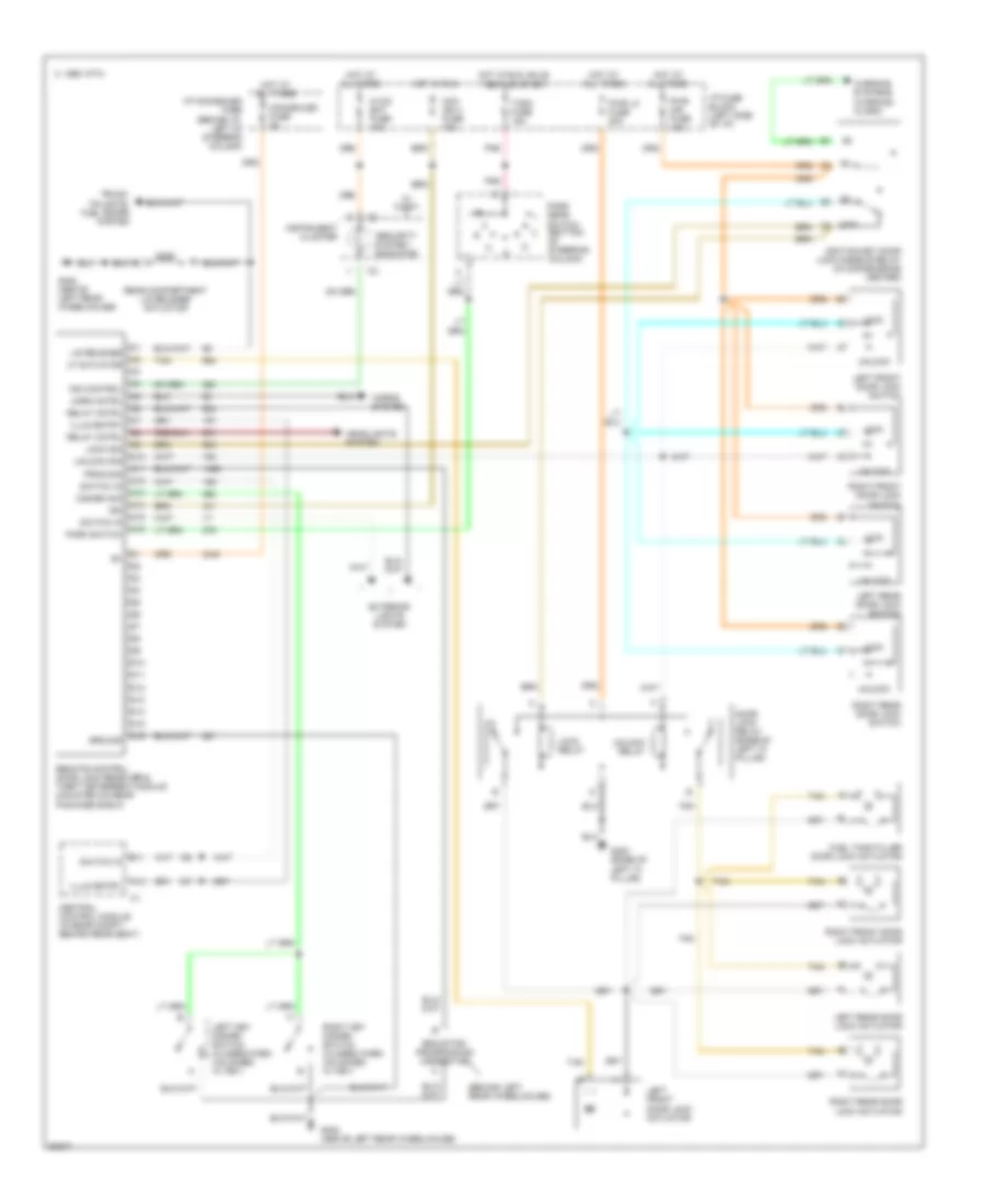
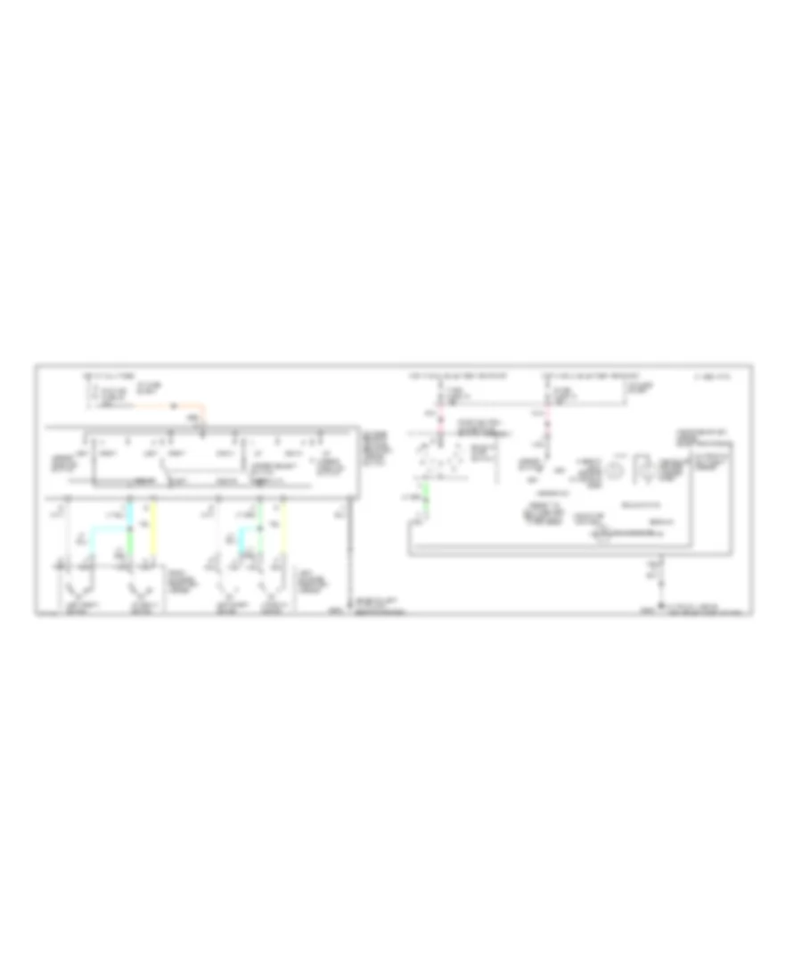
HEADLIGHTS
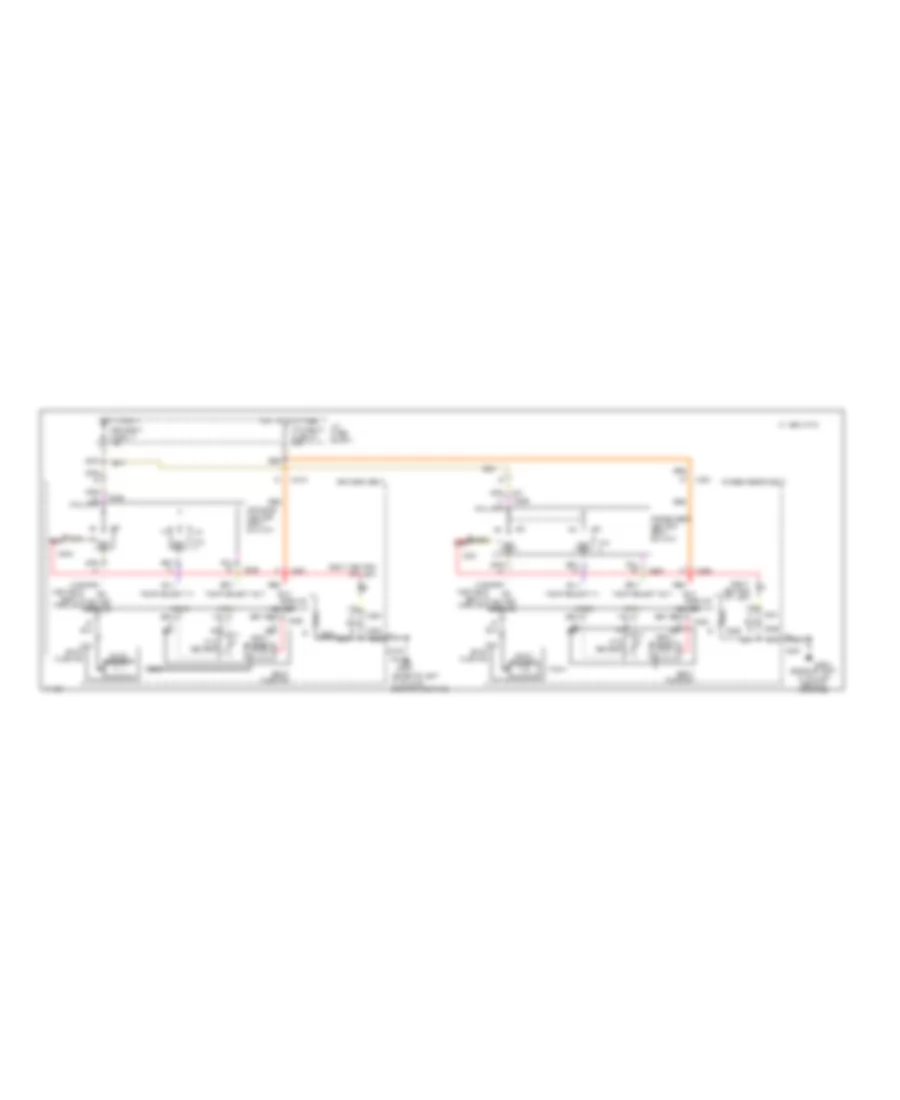
Headlight Wiring Diagram, with DRL for Cadillac Fleetwood 1995
List of elements for Headlight Wiring Diagram, with DRL for Cadillac Fleetwood 1995:
- & backup
- (behind
- (bolted above
- (center of i/p carrier,
- (closed
- (drl) relay
- (in trunk, behind rear seat)
- (left side of i/p, left
- (right
- 10a
- 15a
- 20a
- A10
- A11
- Ambient light sensor
- Assembly
- Battery input
- Below defroster grill)
- Block
- Breaker 5
- Bulb test or start
- C 1995 vftc
- C16
- Ccm bat
- Ccm ign 1
- Ccm ign 3
- Central control module (ccm)
- Circuit
- Cluster
- Conn c1
- Conn c2
- Convenience center
- Daytime
- Delay
- Delay pot return
- Dimmer
- Diode assembly
- Disable
- Drl enable
- Fuse
- Fuse 12
- Fuse 14
- Fuse 18
- Fuse 34
- G106
- G107
- G203
- Hdlp
- Headlamp
- Headlamp automatic control
- Headlamp relay
- Headlamp switch
- Headlamps
- Headlt rly
- Hi beam
- Hot
- Hot at all times
- Hot in
- Hot in run,
- I/p
- Ignition #1
- Ignition #3
- In park)
- In run
- Ind
- Instrument
- Kickpad, base
- Lamp
- Left
- Left headlamp, on
- Lo beam
- Neutral
- Of a pillar)
- Of steering column)
- Park input
- Park/
- Photoresistor hi
- Photoresistor lo
- Pnk
- Pnk 839
- Radiator support)
- Right
- Right headlamp, on
- Run or start
- Running lamps
- Steering column)
- Switch
- T/sig
- Tan
- Tan 270
- Twilight
- Twilight delay pot
- Twilight disable
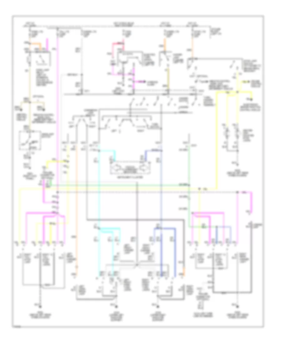
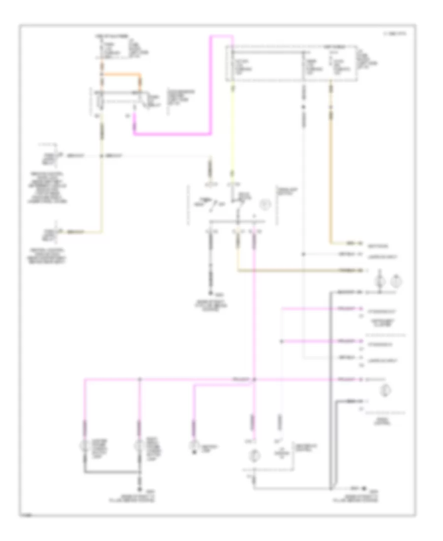
Headlight Wiring Diagram, without DRL for Cadillac Fleetwood 1995
List of elements for Headlight Wiring Diagram, without DRL for Cadillac Fleetwood 1995:
- (behind
- (center of i/p carrier,
- (in trunk, behind rear seat)
- (left side of i/p, left
- (right
- 10a
- 20a
- A10
- A11
- Ambient light sensor
- Battery input
- Below defroster grill)
- Block
- Breaker 5
- C 1995 vftc
- C16
- Ccm bat
- Ccm ign 1
- Ccm ign 3
- Central control module (ccm)
- Circuit
- Cluster
- Conn c1
- Conn c2
- Convenience center
- Delay
- Delay pot return
- Dimmer
- Disable
- Fuse
- Fuse 14
- Fuse 18
- Fuse 34
- G106
- G107
- G203
- Hdlp
- Headlamp
- Headlamp automatic control
- Headlamp relay
- Headlamp switch
- Headlamps
- Headlt rly
- Hi beam
- Hot
- Hot at all times
- Hot in
- I/p
- Ignition #1
- Ignition #3
- In run
- Ind
- Instrument
- Kickpad, base
- Left
- Left headlamp, on
- Lo beam
- Of a pillar)
- Of steering column)
- Photoresistor hi
- Photoresistor lo
- Pnk
- Pnk 839
- Radiator support)
- Right
- Right headlamp, on
- Run or start
- Switch
- Tan
- Tan 270
- Twilight
- Twilight delay pot
- Twilight disable
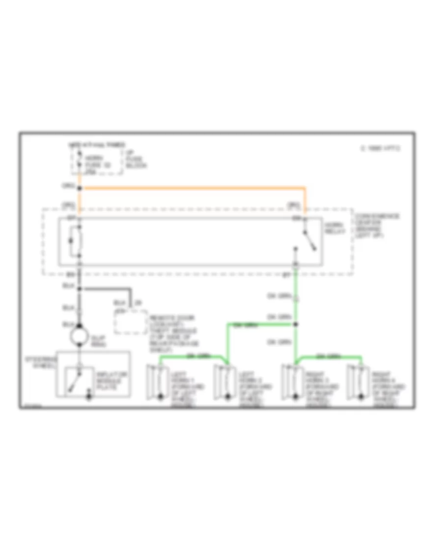
HORN
Horn Wiring Diagram for Cadillac Fleetwood 1995
List of elements for Horn Wiring Diagram for Cadillac Fleetwood 1995:
- C 1995 vftc
- Convenience center (behind left i/p)
- Horn fuse 32 25a
- Horn relay
- Hot at all times
- I/p fuse block
- Inflator module plate
- Left horn 1 (forward of left wheel- house)
- Left horn 2 (forward of left wheel- house)
- Remote door lock/anti- theft module (top side of rear package shelf)
- Right horn 3 (forward of right wheel- house)
- Right horn 4 (forward of right wheel- house)
- Slip ring
- Steering
- Wheel
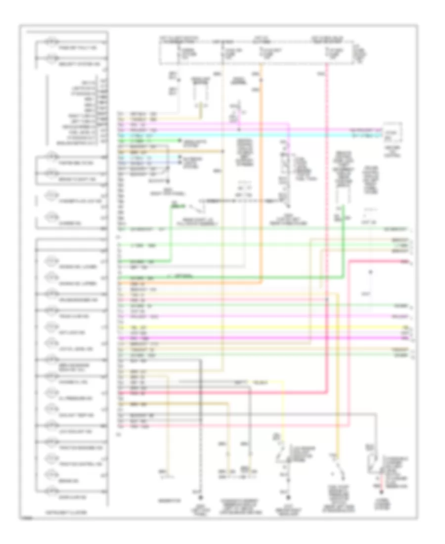
INSTRUMENT CLUSTER
Instrument Cluster Wiring Diagram (1 of 2) for Cadillac Fleetwood 1995
List of elements for Instrument Cluster Wiring Diagram (1 of 2) for Cadillac Fleetwood 1995:
- A10
- A11
- Air bag ind. (lower)
- Air bag ind. (upper)
- Anti-lock ind.
- B10
- B11
- Brake ind.
- Brake to shift ind.
- Central control module (on back seat support, in trunk)
- Change oil ind.
- Charge ind.
- Convenience center)
- Coolant temp ind.
- Cornr lp fuse 10a
- Cruise control module (on left front wheel- house)
- Cruise engaged ind.
- Diagnostic energy
- Door ajar ind.
- E/m
- English/metric out
- Exterior lights system
- Fasten belts ind.
- Fuel level in
- Fuel pump/ engine oil pressure indicator switch (rear left side of engine block)
- Fuel pump/ level sender (top of fuel tank)
- G107 (behind right headlamp)
- G200 (left kick panel)
- G203 (right kick panel)
- G402 (top of left rear wheelhouse)
- Generator
- Grd 1
- Grd 2
- Grd 3
- Headlamp switch
- Headlights system
- Heater- a/c control
- Hot at all times
- Hot in run
- Hot in run, bulb test or start
- Hot w/light switch in head or park
- Hvac bat fuse 10a
- Hvac ign fuse 10a
- I/p fuse block (left
- I/p indc fuse 10a
- I/p)
- Ign 3 in
- Instrument cluster
- Left turn in
- Lights on in
- Low coolant ind.
- Low engine coolant indicator probe
- Low oil level ind.
- Nca
- Oil pressure ind.
- Optional
- Pass key fault ind.
- Pnk
- Radio control
- Rear compt lid pull-down assembly
- Red
- Remote control door lock/ theft deterrent module (rear package shelf)
- Reserve module (left i/p, above
- Right turn in
- Security system ind.
- Service engine soon ind. (mil)
- Tan
- Traction control ind.
- Traction engaged ind.
- Trunk ajar ind.
- Vehicle speed in
- Vf dim
- Vf dimming in
- Vf dimming out
- Washer fluid low ind.
- Windshield washer solvent level switch (in washer fluid reservoir)
- Wiper/ washer system
Instrument Cluster Wiring Diagram (2 of 2) for Cadillac Fleetwood 1995
List of elements for Instrument Cluster Wiring Diagram (2 of 2) for Cadillac Fleetwood 1995:
- Abs ind. ctrl
- Accy
- B11
- B27
- Brake pressure switch (mounted to master cylinder)
- Btsi solenoid
- Btsi switch
- Bulb test
- Change oil output
- Convenience center (right of steering column)
- Coolant temperature switch (forward left side of engine)
- Cruise control system
- Electronic brake and traction control module (forward of left front wheelhouse)
- Engine controls system
- Engine oil level sensor (left side of engine, near drain plug)
- G110 (front of left cylinder head)
- G402 (top of left rear wheelhouse)
- Hot in run, bulb test or start
- Ignition switch
- Left front mini wedge switch assembly
- Left rear mini wedge switch assembly
- Lock
- Low oil lvl input
- Low oil lvl output
- Mil control
- Off
- Park brake switch
- Park gear switch
- Park/neutral position & backup lamp switch assembly (base of steering column)
- Pnk
- Powertrain control module (forward of left front wheelhouse)
- Right front mini wedge switch assembly
- Right rear mini wedge switch assembly
- Run
- Start
- Stop-lamp switch assy (brake pedal bracket)
- Traction engaged ind. ctrl
- Traction ind. ctrl
- Vehicle speed output
- Warning alarm
INTERIOR LIGHTS
Courtesy Lamp Wiring Diagram (1 of 2) for Cadillac Fleetwood 1995
List of elements for Courtesy Lamp Wiring Diagram (1 of 2) for Cadillac Fleetwood 1995:
- (base of right "a" pillar, behind kickpad)
- (in trunk, above left rear wheelhouse)
- A12
- B10
- B11
- B12
- Battery input
- C 1995 vftc
- C12
- Ccm bat fuse #34 10a
- Ccm ign 1 fuse #14 10a
- Ccm ign 3 fuse #18 10a
- Central control module (ccm) (rear compartment, behind rear seat)
- Component center relay (dic)
- Convenience center (left side of i/p)
- Courtesy lmps output
- Courtesy sw
- D/int lts fuse #27 15a
- Dr tamper latch sw
- Elc sens fuse #26 20a
- Frt dr handle sw
- G110 (rear of right cylinder, below exhaust manifold)
- G200 (base of left "a" pillar, behind kickpad)
- G203
- G402
- Garage door opener connector
- Headlamp switch
- Hot at all times
- Hot in run
- Hot in run or start
- I/p compartment lamp #1
- I/p compartment lamp #2
- I/p compartment lamp switch
- I/p fuse block (left side of i/p)
- Ignition #1
- Ignition #3
- Inside rear view mirror
- Int lmps relay
- Left front roof rail courtesy lamp
- Left front side door courtesy lamp
- Left rear roof rail courtesy lamp
- Left rear seat roof vanity mirror
- Left rear side door courtesy lamp
- Left sun- shade mirror
- Lft frt latch sw
- Nca
- Pnk
- Rear compartment courtesy lamp
- Right front roof rail courtesy lamp
- Right front side door courtesy lamp
- Right rear roof rail courtesy lamp
- Right rear seat roof vanity mirror
- Right rear side door courtesy lamp
- Right sun- shade mirror
- Tan
- Underhood lamp
Courtesy Lamp Wiring Diagram (2 of 2) for Cadillac Fleetwood 1995
List of elements for Courtesy Lamp Wiring Diagram (2 of 2) for Cadillac Fleetwood 1995:
- base
- base
- others
- (in trunk, above left rear wheelhouse)
- Base
- Door latch/ tamper
- G402
- Ignition key alarm switch
- Illuminated entry
- Left front mini wedge door lock assembly
- Left front theft deterrent door lock (tamper) switch
- Left rear mini wedge door lock assembly
- Nca
- Others
- Rear compart- ment lid theft deterrent (tamper) switch
- Remote control door lock receiver theft deterrent module (rcdlr/tdm)
- Right front mini wedge door lock assembly
- Right front theft deterrent door lock (tamper) switch
- Right rear mini wedge door lock assembly
- Tan
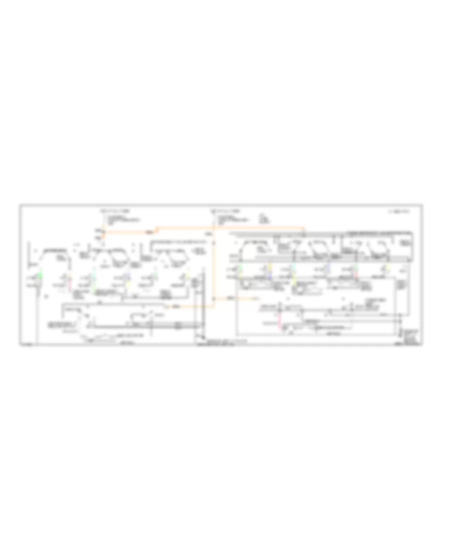
Instrument Illumination Wiring Diagram for Cadillac Fleetwood 1995
List of elements for Instrument Illumination Wiring Diagram for Cadillac Fleetwood 1995:
- (base of right "a" pillar, behind kickpad)
- A2
- Ashtray lamp
- C 1995 vftc
- C16
- C6
- Central control module (ccm) (rear compartment, behind rear seat)
- Convenience center (left side of i/p)
- Crnr lts fuse #42 10a
- G203
- Head
- Headlamp switch
- Heater-a/c control
- Hot at all times
- Hot in run
- Hvac ign fuse #12 10a
- I/p fuse block (left side of i/p)
- Ignition #3
- Instrument cluster
- Int dim lts fuse #42 10a
- Lamps on input
- Master power window switch lamp
- Off
- Park
- Park lamps relay
- Park lp relay
- Park lts fuse #31 20a
- Radio control
- Remote control door lock receiver/theft deterrent module (rcdlr/tdm) (top of rear package shelf, under chmsl cover)
- Right front power window switch lamp
- Solid state
- Vf dimming in
- Vf dimming out
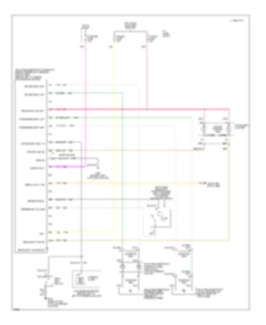
MEMORY SYSTEMS
Memory Seat Wiring Diagram for Cadillac Fleetwood 1995
List of elements for Memory Seat Wiring Diagram for Cadillac Fleetwood 1995:
- 15a
- Back
- Battery
- C 1995 vftc
- C317
- C318
- C319
- C320
- Driver's seat adjuster memory module (below center of left seat)
- Easy exit
- Entire seat
- Forward
- Forward/ back motor (below left front seat)
- Front down
- Front up
- Front up/down motor (below left front seat)
- Frt dn
- Frt up
- Fwd
- G200 (base of left "a" pillar behind kick panel)
- Ground
- Hot at all times
- Hot in run
- Hot in run, bulb test or start
- I/p fuse block
- Ignition 3
- Left power seat switch
- Mem 1
- Mem 2
- Memory 1
- Memory 2
- Nca
- Nca nca
- Park gear switch
- Park position
- Park/neutral and backup lamp switch (on bottom of steering column)
- Pnk
- Pwr recl mem seat fuse 17 10a
- Pwr seat circuit breaker 3 25a
- Rear down
- Rear up
- Right rear up/down motor (below left front seat)
- Rr dn
- Rr up
- Set
- T/sig fuse 12
- Tan
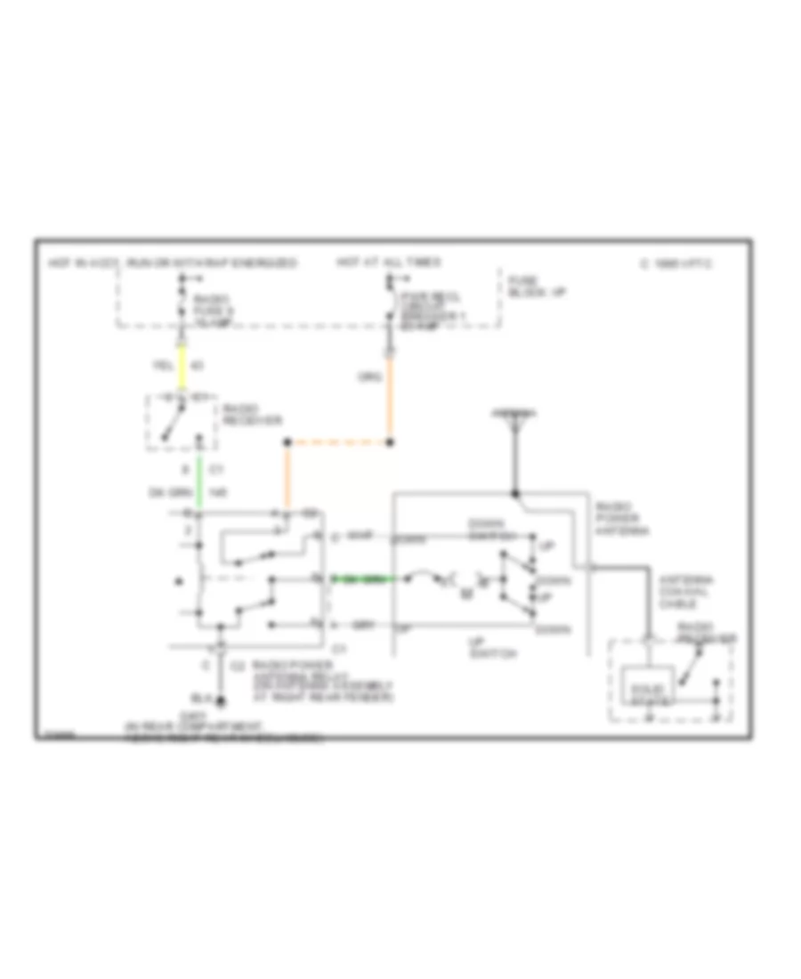
POWER ANTENNA
Power Antenna Wiring Diagram for Cadillac Fleetwood 1995
List of elements for Power Antenna Wiring Diagram for Cadillac Fleetwood 1995:
- (in rear compartment, above right rear wheelhouse)
- Antenna
- Antenna coaxial cable
- C 1995 vftc
- Down
- Down switch
- Fuse block: i/p
- G401
- Hot at all times
- Hot in accy, run or with rap energized
- Pwr recl circuit breaker 1 20 amp
- Radio fuse 9 10 amp
- Radio power antenna
- Radio power antenna relay (on antenna assembly at right rear fender)
- Radio receiver
- Solid state
- Up switch
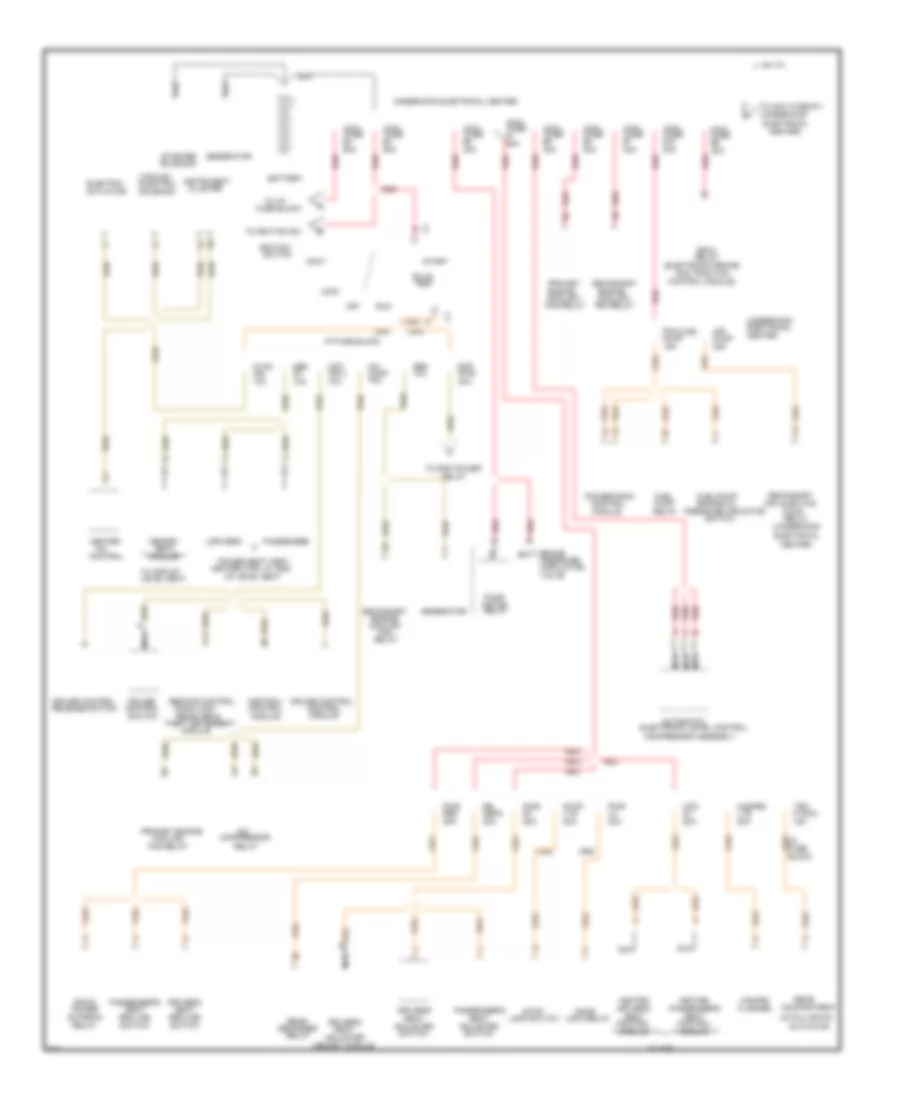
POWER DISTRIBUTION
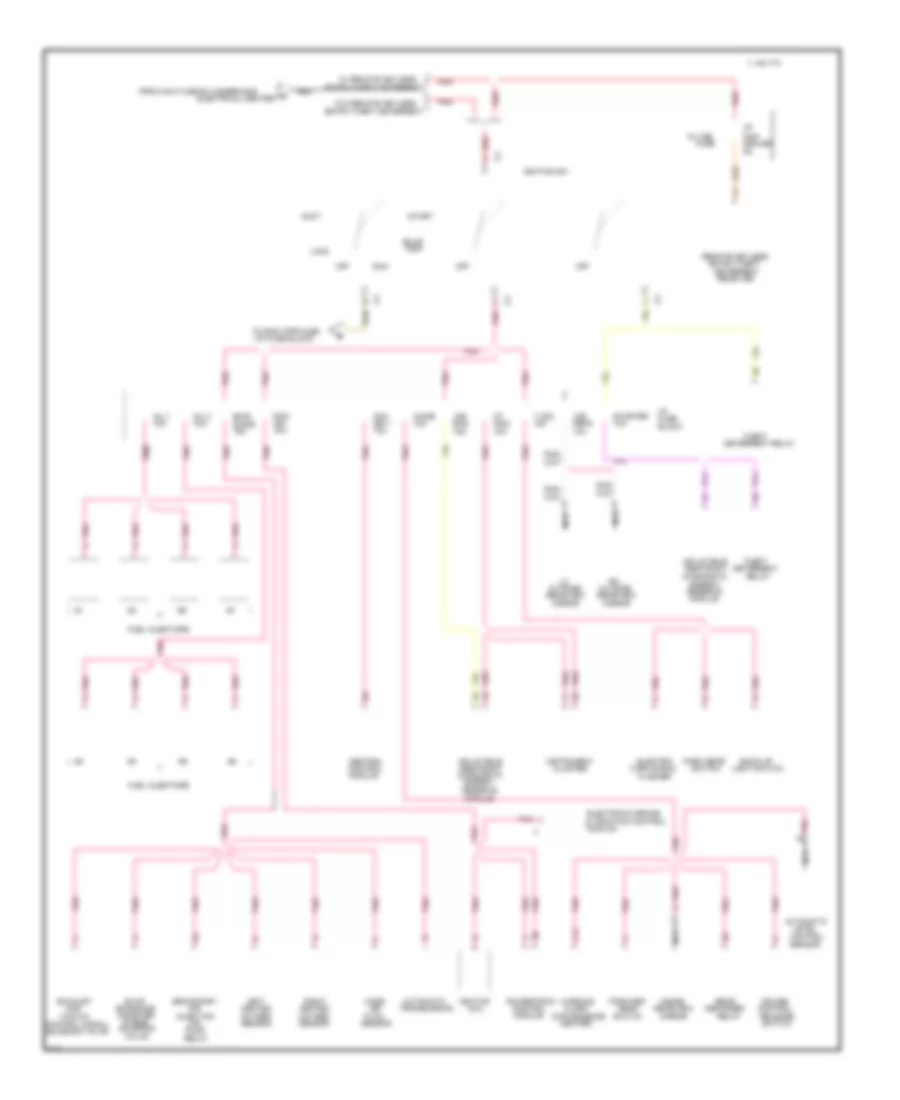
Power Distribution Wiring Diagram (1 of 3) for Cadillac Fleetwood 1995
List of elements for Power Distribution Wiring Diagram (1 of 3) for Cadillac Fleetwood 1995:
- #10
- (electronic brake
- (underhood
- 10a
- 15a
- 20a
- 25a
- 30a
- 40a
- 50a
- 60a
- A/c
- Accy
- Actuator
- Adjuster
- Air
- Air injection
- And traction
- Antenna
- Automatic
- Batt
- Battery
- Block
- Bpmv
- Brake
- Bulb
- C 1995 vftc
- C14
- Ccm
- Center
- Center)
- Central
- Cluster
- Comp
- Compartment
- Compressor
- Compressor assembly
- Control
- Control module)
- Coolant
- Cooling
- Cruise
- Cruise control
- Defg
- Defogger
- Door
- Door lock
- Driver's
- Drivers
- Electric
- Electrical
- Electronic level control
- Engine
- Engine oil
- Fan
- Fan relay
- Flasher
- Fuel
- Fuel/pump
- Fuse
- Fuse block
- Gen
- Generator
- Hazard
- Heated
- Heater
- Heater ctrl w/ ams
- Htd
- Hvac
- I/p
- I/p fuse block
- Ign
- Ign 3
- Ignition
- Instrument
- Lamp switch
- Level seat
- Lid pulldown
- Lock
- Lock relay
- Lts
- Maxi fuse
- Mem
- Memory
- Memory module
- Modulator
- Module
- Motor
- Nca
- Off
- P dwn
- Passenger
- Passenger's
- Pcm fuel
- Power
- Power seat assy
- Powertrain
- Pressure
- Pressure indicator
- Primary
- Primary engine
- Pump
- Pwr
- Radio
- Rap
- Rear
- Rec
- Receiver &
- Recline
- Red
- Relay
- Release switch
- Remote control
- Run
- Seat
- Secondary
- Solenoid
- Start
- Starter
- Stop
- Switch
- Test
- Theft deterrent
- To i/p
- To ignition sw
- To maxi fuse #11
- To rap power
- Trk
- Underhood
- Underhood electrical center
- Up level seat
- Vacuum/
- Valve
- W/ am5
- W/ ams up
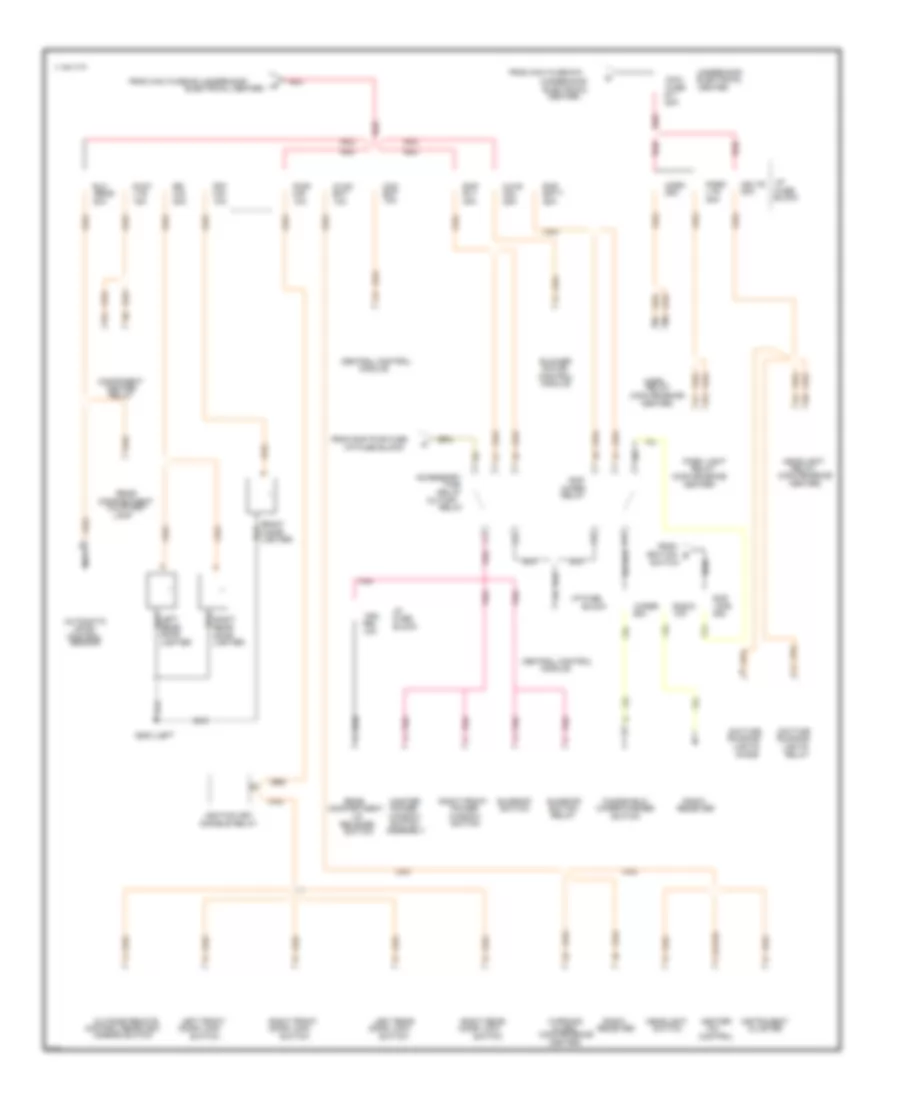
Power Distribution Wiring Diagram (2 of 3) for Cadillac Fleetwood 1995
List of elements for Power Distribution Wiring Diagram (2 of 3) for Cadillac Fleetwood 1995:
- #11
- (convenience
- (i/p fuse block)
- (underhood
- 10a
- 15a
- 20a
- 25a
- 30a
- 50a
- A/c
- Accessory
- Alarm
- Assembly
- Automatic
- Bat
- Batt
- Block
- Blower
- C 1995 vftc
- C12
- Ccm
- Center
- Center)
- Central control
- Cig
- Cigar
- Cluster
- Compartment
- Component
- Control
- Control rearview
- Courtesy
- Cut-off
- D/int
- Daytime
- Delay
- Diode
- Disable relay
- Door
- Door lock
- Elc
- Electrical
- Electrical center)
- From
- From maxi fuse #10
- From maxi fuse #2 (underhood
- From rap pwr fuse
- Front
- Frt
- Fuse
- G200 (left
- Hdlts
- Headlight
- Heater
- Horn
- Hvac
- I/p
- I/p fuse
- Ignition
- Ignition key
- Instrument
- Lamp
- Left
- Left front
- Left rear
- Level
- Lid
- Lighter
- Lights
- Lts
- Master
- Maxi
- Mdl
- Mir
- Mirror switch
- Module
- Motor
- Nca
- Outside remote
- Park
- Park light
- Pnk
- Power
- Pwr
- Radio
- Rap
- Rear
- Receiver
- Red
- Rel
- Relay
- Release
- Right
- Right front
- Right rear
- Rly
- Running
- Sens
- Sensor
- Sunroof
- Switch
- Time
- Trk
- Underhood
- Warning
- Window
- Windshield
- Wiper
- Wiper/washer
- Wpr
Power Distribution Wiring Diagram (3 of 3) for Cadillac Fleetwood 1995
List of elements for Power Distribution Wiring Diagram (3 of 3) for Cadillac Fleetwood 1995:
- & traction control
- (convenience
- (i/p fuse block)
- 10a
- 15a
- A12
- Accy
- Air
- Air
- Alarm
- Automatic
- Back-up
- Bag
- Block
- Bulb
- C 1995 vftc
- Canister
- Ccm
- Cealed
- Center)
- Central
- Chime
- Cluster
- Coil
- Con-
- Control
- Control signal
- Cruise
- Defg
- Defogger
- Deterrent
- Deterrent relay
- Diagnostic
- Electric
- Electrical center)
- Electronic brake
- Emis-
- Emissions
- Energy
- Energy
- Entry/theft
- Entry/theft deterrent
- Evap
- Exhaust
- Flasher
- Flow
- Forward
- From maxi fuse #3 (underhood
- Fuel injectors
- Fuse
- Gas
- Gear
- Heated
- I/p
- Ign
- Ign 1
- Ignition
- Ignition sw
- In line
- Indc
- Inflatable
- Inj 1
- Inj 2
- Injection
- Inside
- Instrument
- Left
- Level
- Light switch
- Lock
- Mass
- Mir
- Mirror
- Module
- Nca
- Off
- Outside
- Oxygen
- Park gear
- Pcm/
- Pnk
- Pnk pnk
- Pnk/
- Powertrain
- Pump
- Purge
- Rear
- Rearview
- Receiver
- Red
- Relay
- Release
- Remote keyless
- Reserve
- Restraint
- Right
- Run
- Secondary
- Sensor
- Sions
- Soleniod
- Solenoid valve
- Start
- Starter
- Switch
- T sig
- Test
- Theft
- To rap wpr fuse
- Transmission
- Turn signal
- Vacuum
- Valve
- W/ remote keyless
- W/o remote keyless
- Warning
POWER DOOR LOCKS
Keyless Entry & Anti-Theft Wiring Diagram for Cadillac Fleetwood 1995
List of elements for Keyless Entry & Anti-Theft Wiring Diagram for Cadillac Fleetwood 1995:
- "security system" indicator
- (behind left rear wheelhouse)
- 87a
- A12
- B11
- C 1995 vftc
- C10
- C11
- C12
- C13
- C14
- C15
- C16
- Ccm ign 3 fuse 10a
- Central control module (in rear compt, behind rear seat)
- Concealed fuse 5a
- D10
- D11
- D12
- D13
- D14
- D15
- D16
- Disarm sig
- Door lock relay (base of left "a" pillar)
- Exterior lights system
- Fuel tank filler door lock actuator
- G200 (base of left "a" pillar)
- G402 (above left rear wheelhouse)
- Ground
- Headlights system
- Horn cntrl
- Horns system
- Hot at all times
- Hot in run
- Hot in run, bulb test or start
- Hvac bat fuse 10a
- I/p concealed fuse (behind i/p, left of steering column)
- I/p fuse block (left side of i/p)
- Ign
- Ignition key door lock disable relay (in convenience center)
- Illum entry
- Ind control
- Instrument cluster
- Left front door lock actuator
- Left front door lock switch
- Left key disarm switch (closes when unlocked w/ key)
- Left rear door lock actuator
- Left rear door lock switch
- Lf actuator
- Lid release
- Lock
- Lock relay
- Lock sig
- Park gear switch (bottom of steering column)
- Park switch
- Pnk
- Prog sig
- Pwr lk fuse 20a
- Pwr mir fuse 10a
- Rcdlr/tdm programming connector
- Rear compartment lid release actuator
- Relay cntrl
- Remote control door lock receiver & theft deterrent module (mounted on rear package shelf)
- Right front door lock actuator
- Right front door lock switch
- Right key disarm switch (closes when unlocked w/ key)
- Right rear door lock actuator
- Right rear door lock switch
- Switch in
- T/sig fuse 15a
- Tan
- Trunk, tailgate, fuel doors system
- Unlock
- Unlock relay
- Unlock sig
- W/ theft
- Warning systems (warning alarm)
POWER MIRRORS
Power Mirror Wiring Diagram for Cadillac Fleetwood 1995
List of elements for Power Mirror Wiring Diagram for Cadillac Fleetwood 1995:
- (base of left "a" pillar, behind kickpad)
- (in trunk, above left rear wheelhouse)
- Ambient light sensor (winshield side)
- Automatic day/night mirror
- B nca
- Backup lamp switch
- C 1995 vftc
- Chime fuse 13 10a
- Down
- G200
- G402
- Ground
- Headlamp sensor (mirror side)
- Hot at all times
- Hot in run, bulb test or start
- I/p fuse block
- Indicator control
- Inside rearview mirror (electro-chromic)
- Left
- Left outside rearview mirror
- Left/right motor
- Mirror "on"
- Mirror position switch
- Mirror select switch
- Mirror switch
- Nca
- Off
- On indicator
- Outside remote control rearview mirror switch
- Park/neutral and backup switch assembly
- Pnk
- Pwr mir fuse 35 10a
- Reset to daytime high reflectivity in reverse
- Right
- Right outside rearview mirror
- Solid state
- T/sig fuse 12 15a
- Up/down motor
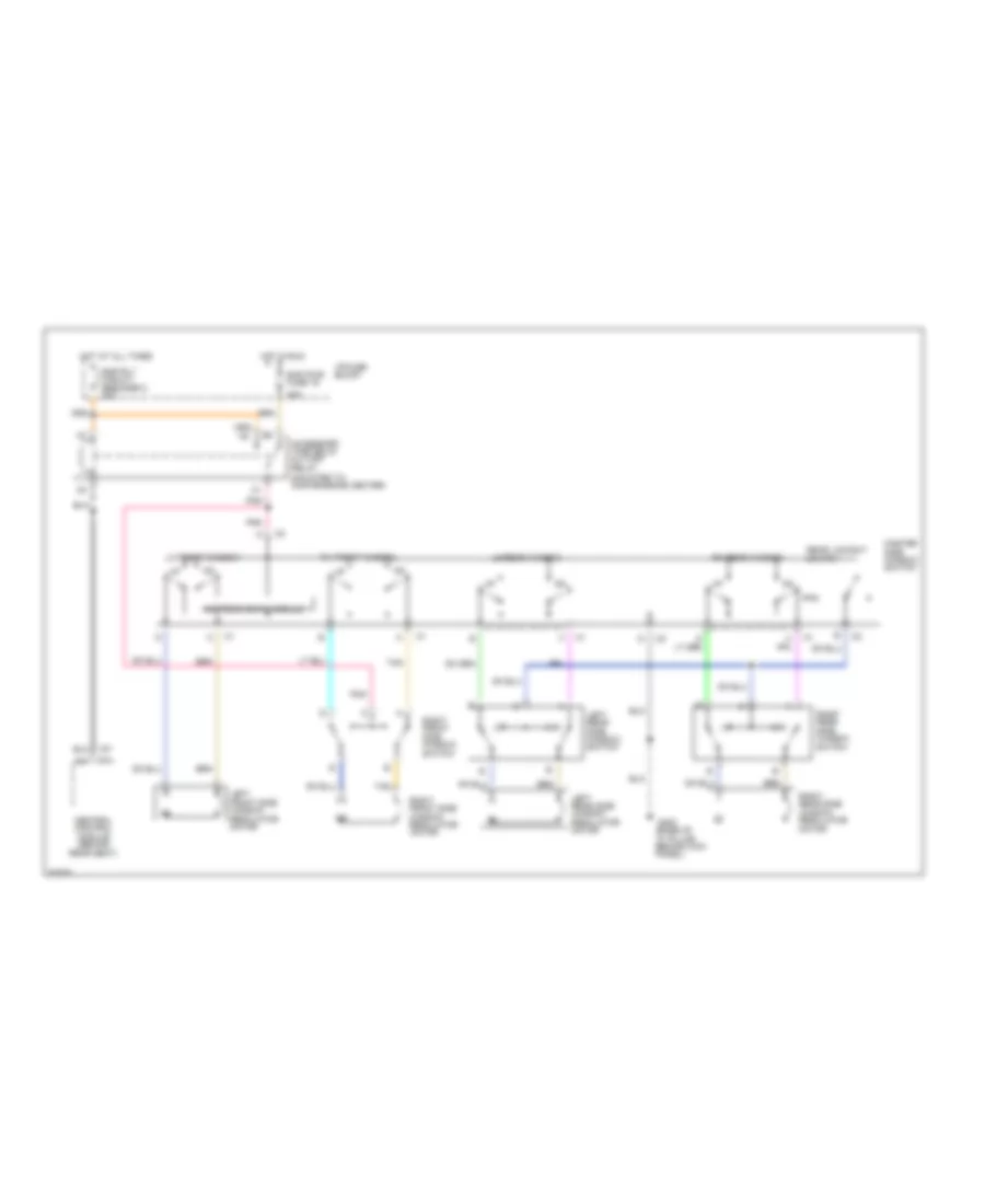
POWER SEATS
6-Way & Recliner Power Seat Wiring Diagram for Cadillac Fleetwood 1995
List of elements for 6-Way & Recliner Power Seat Wiring Diagram for Cadillac Fleetwood 1995:
- (base of left "a" pillar behind kickpad)
- Back
- C 1995 vftc
- Down
- Driver's seat adjuster switch
- Driver's seat recline switch
- E tan
- Entire seat
- For- ward
- Forward
- Forward/ back motor
- Front height
- Front height motor
- G200
- Hot at all times
- I/p fuse block
- Left front seat
- Passenger seat recline switch
- Passenger's seat adjuster switch
- Pwr recl circuit breaker 1 20a
- Pwr seat circuit breaker 3 25a
- Rear height
- Rear height motor
- Recline motor
- Right front seat
Heated Seats Wiring Diagram for Cadillac Fleetwood 1995
List of elements for Heated Seats Wiring Diagram for Cadillac Fleetwood 1995:
- g200
- (base of left "a" pillar behind kickpad)
- (base of left a" pillar, behind kickpad)
- 5.9 k
- B red
- Back cushion
- Back element
- Bat
- C 1995 vftc
- C316
- C321
- C322
- C323
- C324
- C325
- C327
- C328
- C329
- C330
- C331
- C332
- Driver's heated seat switch
- Driver's seat
- G200
- Ground
- Heated seat module
- Heater
- Heater ground
- Hot at all times
- Hot in run
- Htd seat fuse 40 15a
- I/p fuse block
- Ign
- Mem seat fuse 17 10a
- Nca
- Ntc 1
- Ntc 2
- Ntc sensor
- Off
- Passenger heated seat switch
- Passenger's seat
- Red
- Seat cushion
- Seat element
- Seat heater "on" led
- Temp select in
- Temp select out
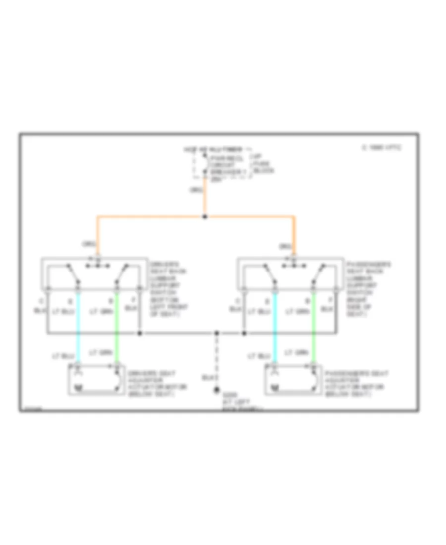
Lumbar Wiring Diagram for Cadillac Fleetwood 1995
List of elements for Lumbar Wiring Diagram for Cadillac Fleetwood 1995:
- C 1995 vftc
- Driver's seat adjuster actuator motor (below seat)
- Driver's seat back lumbar support switch (bottom left front of seat)
- G200 (at left kick panel)
- Hot at all times
- I/p fuse block
- Passenger's seat adjuster actuator motor (below seat)
- Passenger's seat back lumbar support switch (right side of seat)
- Pwr recl circuit breaker 1 20a
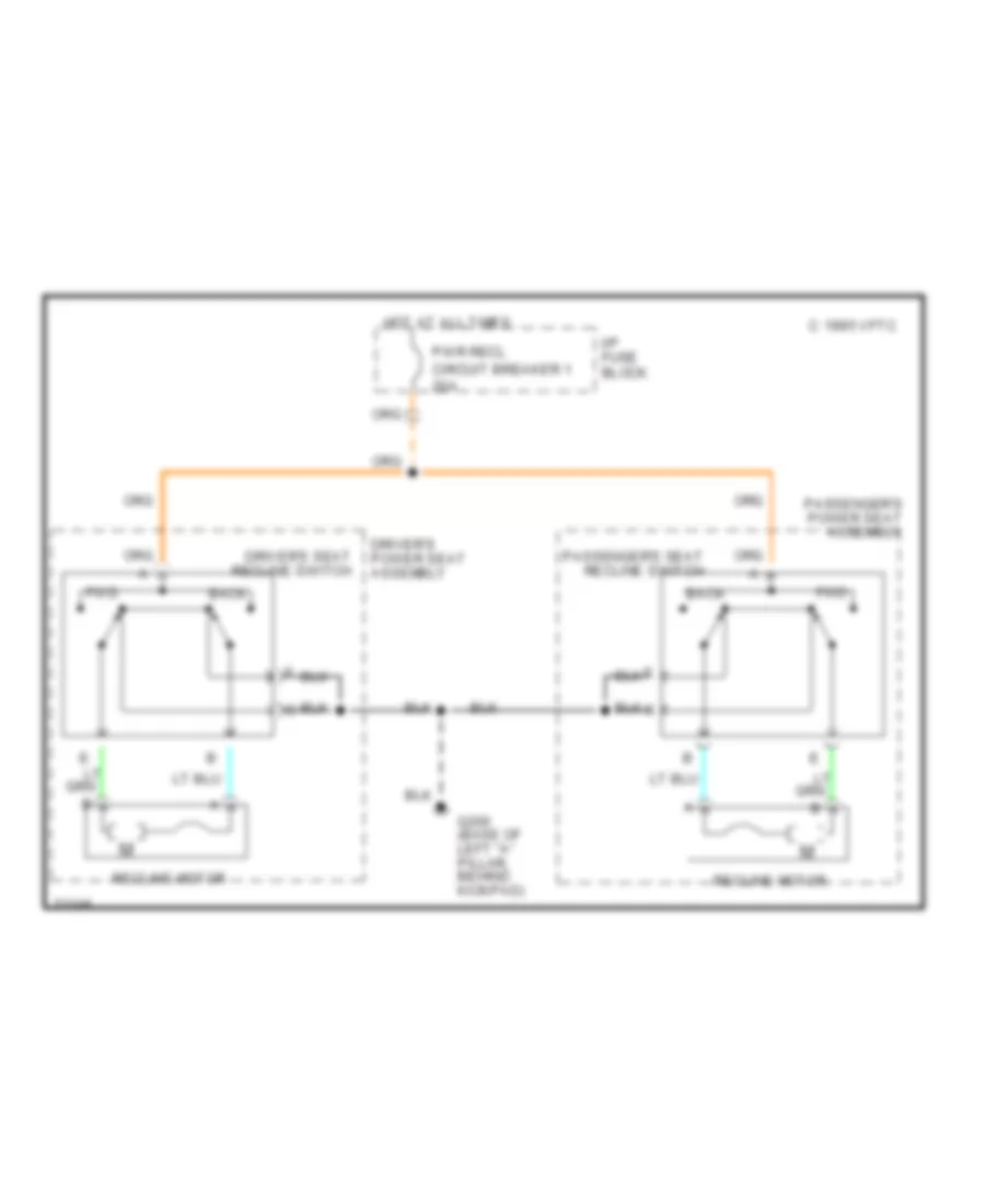
Recliner Wiring Diagram for Cadillac Fleetwood 1995
List of elements for Recliner Wiring Diagram for Cadillac Fleetwood 1995:
- Back
- C 1995 vftc
- Driver's power seat assembly
- Driver's seat recline switch
- Fwd
- G200 (base of left "a" pillar, behind kickpad)
- Hot at all times
- I/p fuse block
- Passenger's power seat assembly
- Passenger's seat recline switch
- Pwr recl circuit breaker 1 20a
- Recline motor
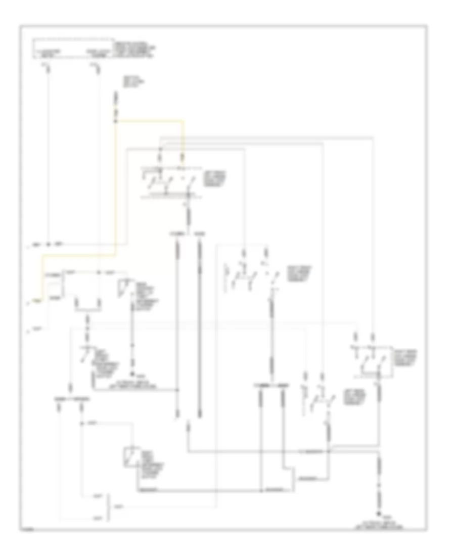
POWER TOP/SUNROOF
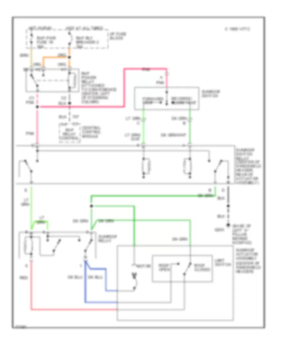
Sunroof Wiring Diagram for Cadillac Fleetwood 1995
List of elements for Sunroof Wiring Diagram for Cadillac Fleetwood 1995:
- (base of left "a" pillar, behind kickpad)
- C 1995 vftc
- C1 pnk
- Central control module
- Forward/ vent
- G200
- Hot at all times
- Hot in run
- I/p fuse block
- Limit switch
- Motor
- Pnk
- Rap power relay (attached to convenience center, left of steering column)
- Rap pwr fuse 19 30a
- Rap relay control
- Rap rly breaker 2 30a
- Red
- Reverse/ close vent
- Roof closed
- Roof open
- Sunroof actuator assembly (center of windshield header)
- Sunroof relay
- Sunroof switch
- Sunroof switch relay (center of windshield header, rear of actuator assembly)
POWER WINDOWS
Power Window Wiring Diagram for Cadillac Fleetwood 1995
List of elements for Power Window Wiring Diagram for Cadillac Fleetwood 1995:
- 30a
- Accessory time delay cut-off relay (mounted to convenience center)
- Central control module (behind rear seat)
- Express down module
- G200 (base of "a" pillar behind kick panel)
- Hot at all times
- Hot in run
- I/p fuse block
- Left front side window regulator motor
- Left rear side window regulator motor
- Left rear side window switch
- Lh front window
- Lh rear window
- Master side window switch
- Pnk
- Rap pwr fuse 19
- Rap rly circuit breaker 2 30a
- Rear lockout switch
- Rh front window
- Rh rear window
- Right front side window regulator motor
- Right front side window switch
- Right rear side window regulator motor
- Right rear side window switch
- Tan
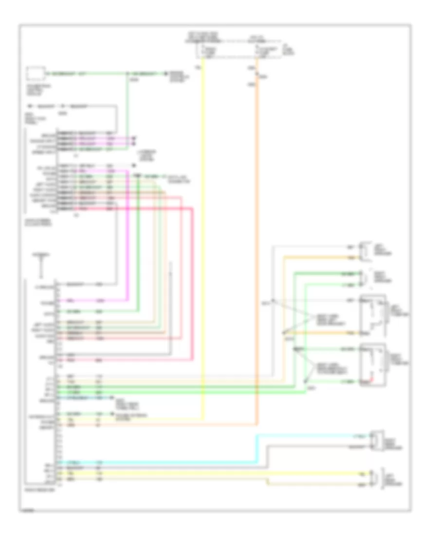
RADIO
Radio Wiring Diagrams for Cadillac Fleetwood 1995
List of elements for Radio Wiring Diagrams for Cadillac Fleetwood 1995:
- (body harn, near breakout to power seat)
- (body harn, near left door grommet)
- 14v
- Am/fm stereo & clock radio
- Antenna
- Antenna out
- Audio com
- Audio common
- Data
- Data link connector
- Dimming input
- Engine controls system
- G203 (right kick panel)
- G403 (right rear wheelwell)
- Ground
- Hi ground
- Hot at all times
- Hot in acc, run or w/ retained accessory power
- Hvac/bat fuse 10a
- I/p fuse block
- Interior lights system
- Left audio
- Left front speaker
- Left front tweeter
- Left rear speaker
- Lf (+)
- Lf (-)
- Lr (+)
- Lr (-)
- Mem
- Memory
- Memory pwr
- Nca
- Pk lps on
- Pnk
- Power
- Power antenna system
- Powertrain control module
- Radio fuse 10a
- Radio receiver
- Red
- Rf (+)
- Rf (-)
- Right audio
- Right front speaker
- Right front tweeter
- Right rear speaker
- Rr (+)
- Rr (-)
- S206
- S210
- S246
- S254
- S314
- S315
- S320
- S321
- Speed input
- Tan
- Vf dimming
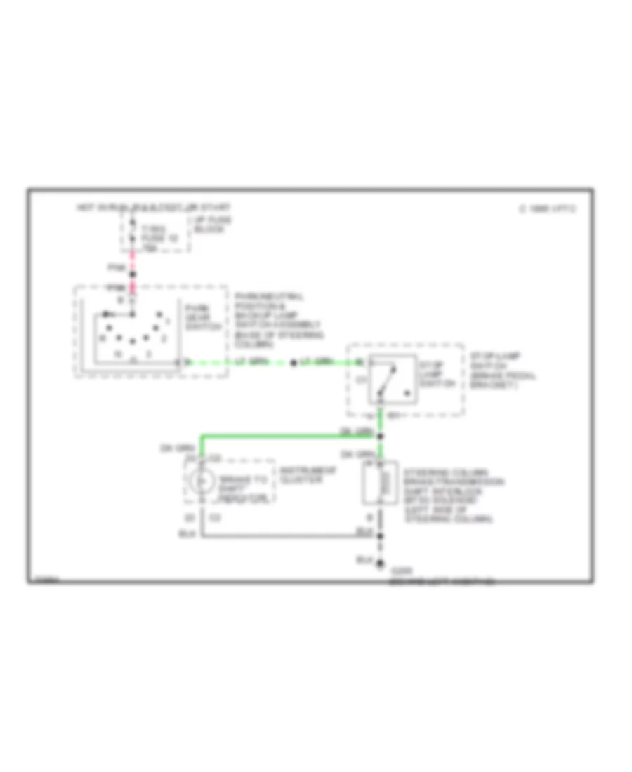
SHIFT INTERLOCKS
Shift Interlock Wiring Diagram for Cadillac Fleetwood 1995
List of elements for Shift Interlock Wiring Diagram for Cadillac Fleetwood 1995:
- "brake to shift" indicator
- C 1995 vftc
- G200 (behind left kickpad)
- Hot in run, bulb test or start
- I/p fuse block
- Instrument cluster
- Park gear switch
- Park/neutral position & backup lamp switch assembly (base of steering column)
- Pnk
- Steering column brake/transmission shift interlock (btsi) solenoid (left side of steering column)
- Stop lamp switch
- Stop-lamp switch (brake pedal bracket)
- T/sig fuse 12 15a
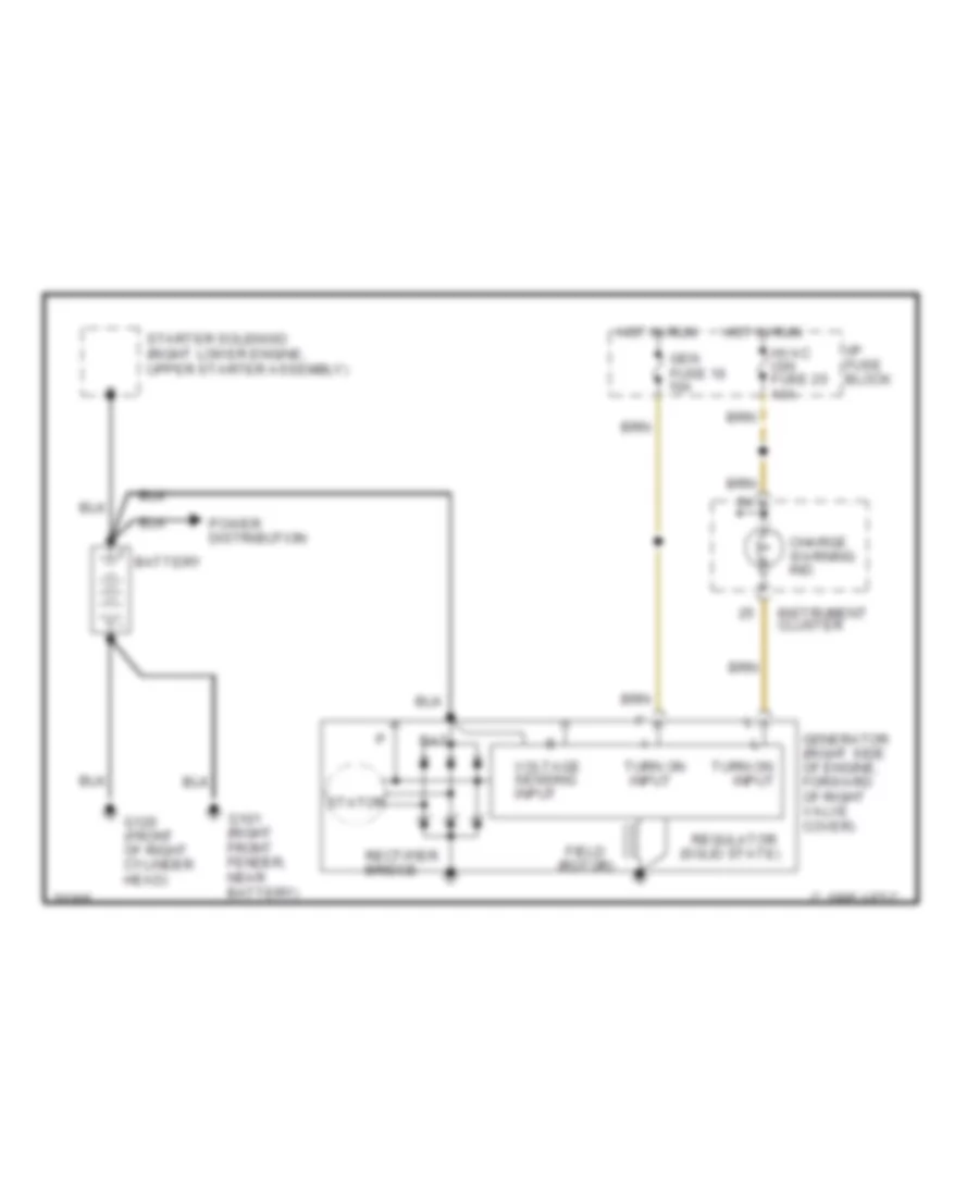
STARTING/CHARGING
Charging Wiring Diagram for Cadillac Fleetwood 1995
List of elements for Charging Wiring Diagram for Cadillac Fleetwood 1995:
- (solid state)
- Bat
- Battery
- C 1995 vftc
- Charge warning ind.
- Field (rotor)
- G101 (right front fender, near battery)
- G120 (front of right cylinder head)
- Gen fuse 16 10a
- Generator (right side of engine, forward of right valve cover)
- Hot in run
- Hvac ign fuse 25 10a
- I/p fuse block
- Input
- Instrument cluster
- Power distribution
- Rectifier bridge
- Regulator
- Starter solenoid (right lower engine, upper starter assembly)
- Stator
- Turn on
- Turn on input
- Voltage sensing input
Starting Wiring Diagram for Cadillac Fleetwood 1995
List of elements for Starting Wiring Diagram for Cadillac Fleetwood 1995:
- #24
- 10a
- Accy
- Bat
- Battery
- Bulb test
- C 1995 vftc
- Central control module (in rear compt, behind rear seat)
- D13
- G101 (right front fender, near battery)
- G120 (front of right cylinder head)
- Generator
- Hold-in coil
- I/p fuse block
- Ignition switch
- Lock
- Maxi- fuse 3 50a ign 1
- Off
- Pull-in coil
- Red
- Run
- Solenoid contacts
- Start
- Start enable
- Starter fuse
- Starter motor
- Starter solenoid (right lower engine, upper starter assembly)
- Theft deterrent relay (right side of i/p, mounted to carrier)
- Underhood electrical center
SUPPLEMENTAL RESTRAINTS
Supplemental Restraint Wiring Diagram for Cadillac Fleetwood 1995
List of elements for Supplemental Restraint Wiring Diagram for Cadillac Fleetwood 1995:
- (lower)
- (upper)
- 8.45 k
- A10
- Air bag fuse 15a
- Air bag warning inds
- B10
- C 1995 vftc
- Computer data lines
- Convenience center (behind left i/p, left of steering column)
- Crank input
- Driver seat belt in
- Driver side "high"
- Driver side "low"
- G200 (base of left "a" pillar kick pad)
- G200 (base of left "a" pillar, behind kick pad)
- Ground
- Hot in run, bulb test or start
- Hot in start
- I/p fuse block
- I/p indic fuse 10a
- Ign 1
- Inflatable restraint diagnostic energy reserve (w/ sensor) module (sdm) (behind left i/p, above convenience center)
- Inflatable restraint front end sheet metal sensor (on center radiator support)
- Inflatable restraint i/p inflator module (below right i/p top cover)
- Inflatable restraint steering wheel inflator module (center of steering wheel)
- Inflatable restraint steering wheel module coil (top of steering column)
- Instrument cluster
- Nca
- Passenger side "high"
- Passenger side "low"
- Pnk
- Primary sir ind
- Redundant ind ground
- Redundant ind ign 1
- Redundant sir ind
- Reference voltage
- Seat belt input
- Seat belt switch
- Sensor signal
- Serial data line
- Shorting bar
- Starter fuse 10a
- Tan
- Warning alarm
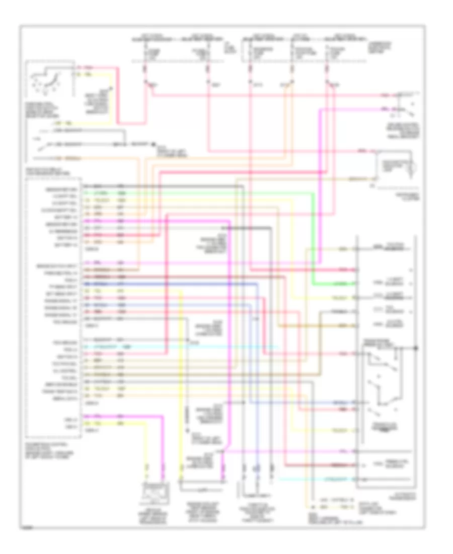
TRANSMISSION
5.7L
5.7L (VIN P), Transmission Wiring Diagram for Cadillac Fleetwood 1995
List of elements for 5.7L (VIN P), Transmission Wiring Diagram for Cadillac Fleetwood 1995:
- 1-2 shift
- 1-2 shift sol
- 2-3 shift sol
- 2-3 shift solenoid
- 3-2 ctrl solenoid
- 3-2 downshift sol
- 5v reference
- Automatic transmission
- Battery in
- Brake switch input
- Chime fuse 10a
- Conn a
- Conn b
- Conn c
- Conn d
- Cruise control release switch (on brake pedal bracket)
- Data link connector (left side of dash)
- Ect sens input
- Emissions fuse 20a
- Engine coolant temp sensor (front of engine, near thermo- stat housing)
- G110 (front of left cylinder head)
- Hot at all times
- Hot in run, bulb test or start
- I/p fuse block
- I/p indc fuse 10a
- Ignition in
- Instrument cluster
- Malfunction indicator lamp
- Mil control
- Park/neutral in
- Park/neutral position switch (base of gear selector lever)
- Pcm ground
- Pcm/fuel pump fuse 15a
- Pcm/ign fuse 10a
- Pcs hi
- Pcs lo
- Pnk
- Pnk pnk
- Pnp switch relay (convenience center)
- Powertrain control module (pcm) (engine compt, forward of left shock tower)
- Press ctrl
- Press sw assy
- Range signal "a"
- Range signal "b"
- Range signal "c"
- Red
- S110
- S113
- S116 (engine harn, 28 cm from wiper motor)
- S118 (engine harn, 4 cm from vss harness break-out)
- S132
- S134 (engine harn, 11 cm from tps connector break-out)
- S136
- S139 (engine harn, 7 cm from wiper motor)
- S201
- S215
- S223 (body harness, forward of left "b" pillar)
- S231
- S279 (body harn, 20 cm from turn signal switch break-out)
- Sensor return
- Serial data
- Service enable
- Solenoid
- Tan
- Tcc
- Tcc pwm
- Tcc pwm sol
- Tcc sol
- Throttle position position (mounted to side of throttle body)
- Tp sens input
- Trans fluid temp sensor
- Trans range
- Trans temp sig in
- Underhood electrical center
- Vehicle speed sensor (left rear of transmission)
- Vss hi
- Vss lo
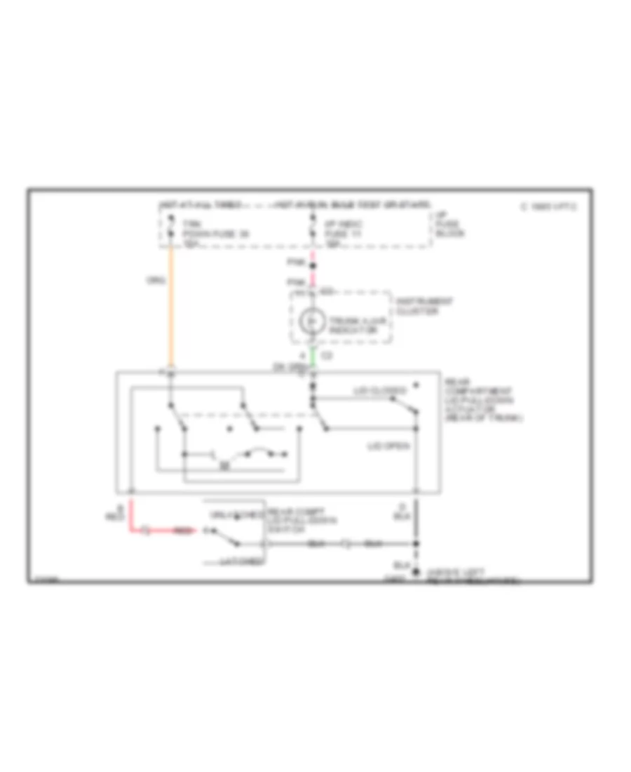
TRUNK, TAILGATE, FUEL DOOR
Trunk Pull-Down Wiring Diagram for Cadillac Fleetwood 1995
List of elements for Trunk Pull-Down Wiring Diagram for Cadillac Fleetwood 1995:
- (above left rear wheelhouse)
- B red
- C 1995 vftc
- G402
- Hot at all times
- Hot in run, bulb test or start
- I/p fuse block
- I/p indic fuse 11 10a
- Instrument cluster
- Latched
- Lid closed
- Lid open
- Pnk
- Rear compartment lid pull-down actuator (rear of trunk)
- Rear compt lid pull-down switch
- Red
- Trk pdwn fuse 36 15a
- Trunk ajar indicator
- Unlatched
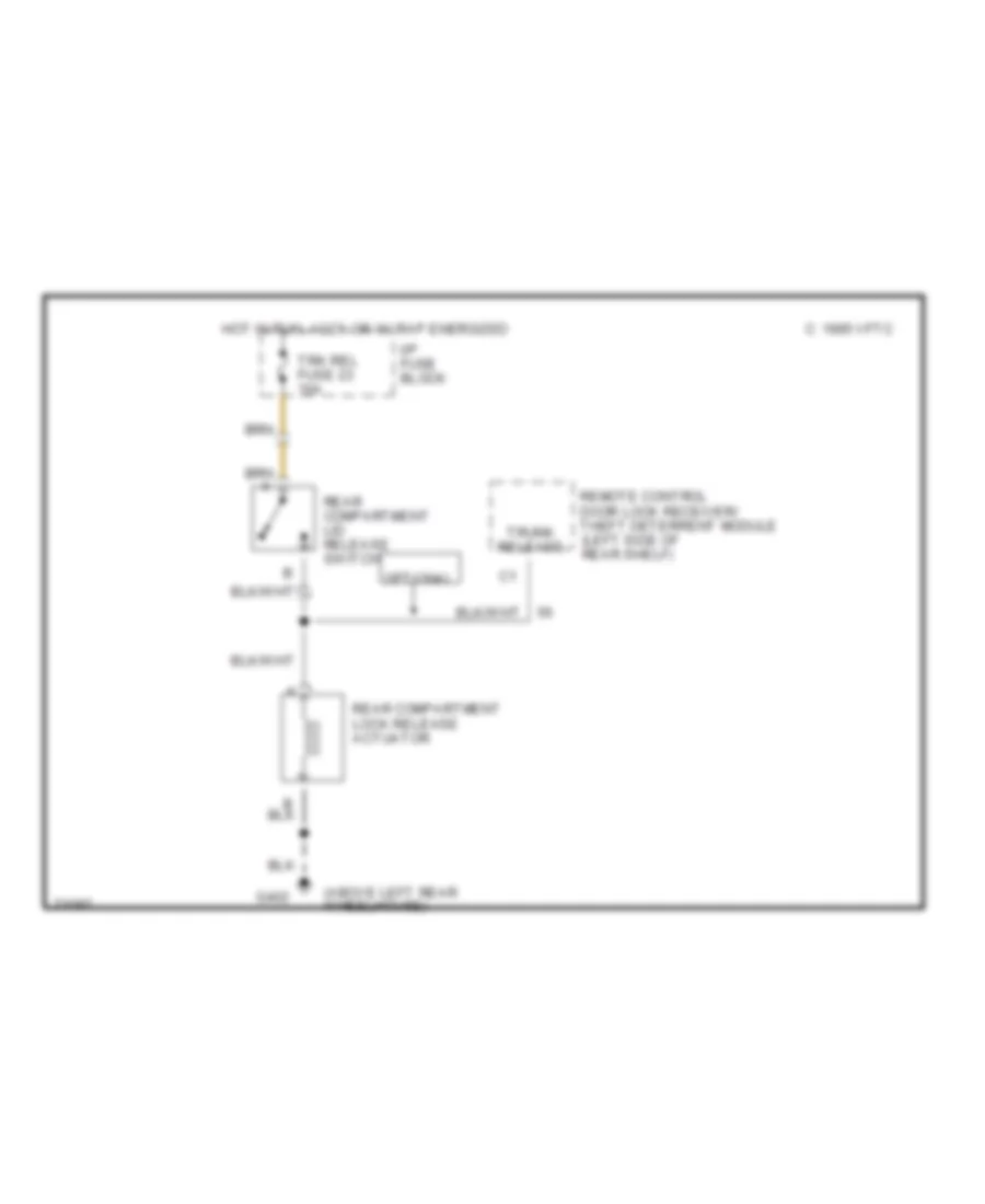
Trunk Release Wiring Diagram for Cadillac Fleetwood 1995
List of elements for Trunk Release Wiring Diagram for Cadillac Fleetwood 1995:
- (above left rear wheelhouse)
- C 1995 vftc
- G402
- Hot in run, accy or w/ rap energized
- I/p fuse block
- Optional
- Rear compartment lid release switch
- Rear compartment lock release actuator
- Remote control door lock receiver/ theft deterrent module (left side of rear shelf)
- Trk rel fuse 23 10a
- Trunk release
WARNING SYSTEMS
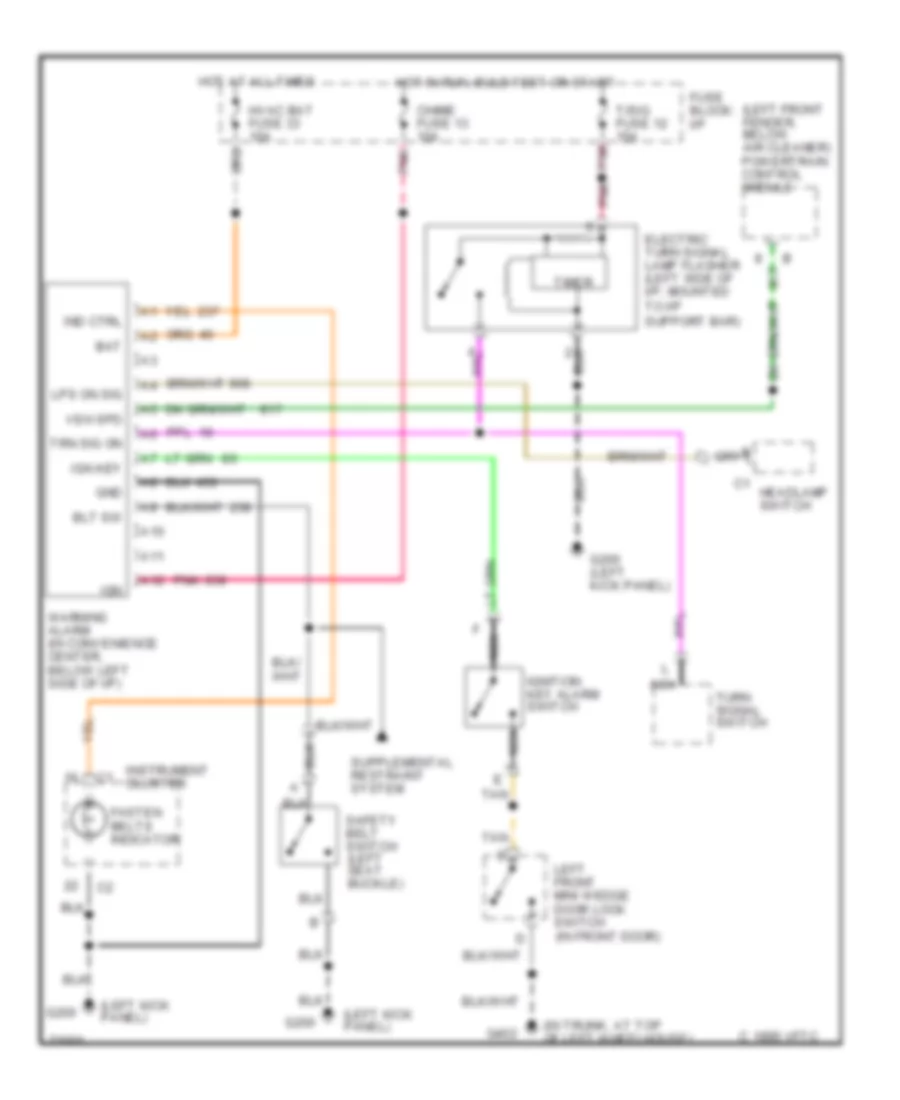
Warning System Wiring Diagrams for Cadillac Fleetwood 1995
List of elements for Warning System Wiring Diagrams for Cadillac Fleetwood 1995:
- (in trunk, at top of left wheelhouse)
- (left front fender, below air cleaner) powertrain control module
- (left kick panel)
- A10
- A11
- A12
- Bat
- Blt sw
- C 1995 vftc
- Chime fuse 13 10a
- Electric turn signal lamp flasher (left side of i/p, mounted to i/p support bar)
- Fasten belts indicator
- Fuse block: i/p
- G200
- G200 (left kick panel)
- G402
- Gnd
- Headlamp switch
- Hot at all times
- Hot in run, bulb test or start
- Hvac bat fuse 33 10a
- Ign
- Ign key
- Ignition key alarm switch
- Ind ctrl
- Instrument cluster
- Left front mini wedge door lock switch (in front door)
- Lps on sig
- Nca
- Pnk
- Safety belt switch (left seat buckle)
- T/sig fuse 12 15a
- Tan
- Timer
- Trn sig on
- Turn signal switch
- Veh spd
- Warning alarm (in convenience center, below left side of i/p)
WIPER/WASHER
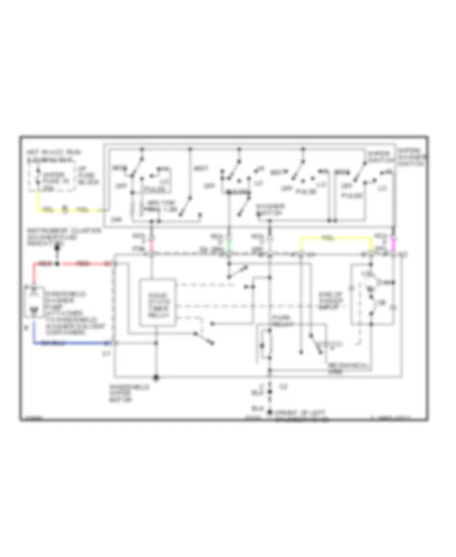
Wiper/Washer Wiring Diagram for Cadillac Fleetwood 1995
List of elements for Wiper/Washer Wiring Diagram for Cadillac Fleetwood 1995:
- (front of left cylinder head)
- 24k
- C 1995 vftc
- End of sweep input
- G110
- Hot in acc, run & during rap
- I/p fuse block
- Instrument cluster (washer fluid indicator)
- Mechanical arm
- Min 110k max 1.2m
- Mist
- Nca f pnk f
- Off
- Park relay
- Pulse
- Red
- Solid state timer relay
- Washer switch
- Windshield washer pump (attached to windshield washer solvent container)
- Windshield wiper motor
- Wiper fuse 10 25a
- Wiper switch
- Wiper/ washer switch

 Čeština
 Dansk
Dansk Deutsch
 Ελληνικά
 English
 English
 Suomi
Suomi Français
 Français
 עברית
עברית Hrvatski
 Magyar
 Italiano
 日本語
日本語 한국어
한국어 Nederlands
 Polski
 Português
 Português
 Română
 Русский
 Slovenčina
 Slovenščina
 Svenska
 Türkçe
 中文 (中国)