AIR CONDITIONING
A/C Wiring Diagram for Chevrolet Astro 1995
 https://portal-diagnostov.com/license.html
Automotive Electricians Portal FZCO
Automotive Electricians Portal FZCO
https://portal-diagnostov.com/license.html
https://portal-diagnostov.com/license.html
Automotive Electricians Portal FZCO
Automotive Electricians Portal FZCO
List of elements for A/C Wiring Diagram for Chevrolet Astro 1995:
- (on left radiator support)
- (on radiator support, near right headlight)
- A/c compressor
- A/c high pressure cutout switch
- A/c low pressure cutout switch
- A/c on input
- Aux htr a/c fuse 25a
- B/l
- Blend
- Blower motor
- Blower motor resistor (on blower motor housing)
- Blower switch
- C (1995)
- Convenience center
- Def
- Diode
- E12
- Fuse block
- Fusible link
- G (1994)
- G108
- G109
- G115 (rear of engine)
- Heater and a/c control assembly
- Hi a/c blower relay (on multi- use bracket, at right side of cowl)
- Hot at all times
- Hot in run
- Htr
- Htr a/c fuse 20a
- Interior lights
- Max
- Med
- Norm
- Off
- Power- train control module (right plenum side panel)
- Rear auxiliary heater blower motor assembly (behind left rear wheel well)
- Rear blower switch
- Red
- System
- Tan
- Vent
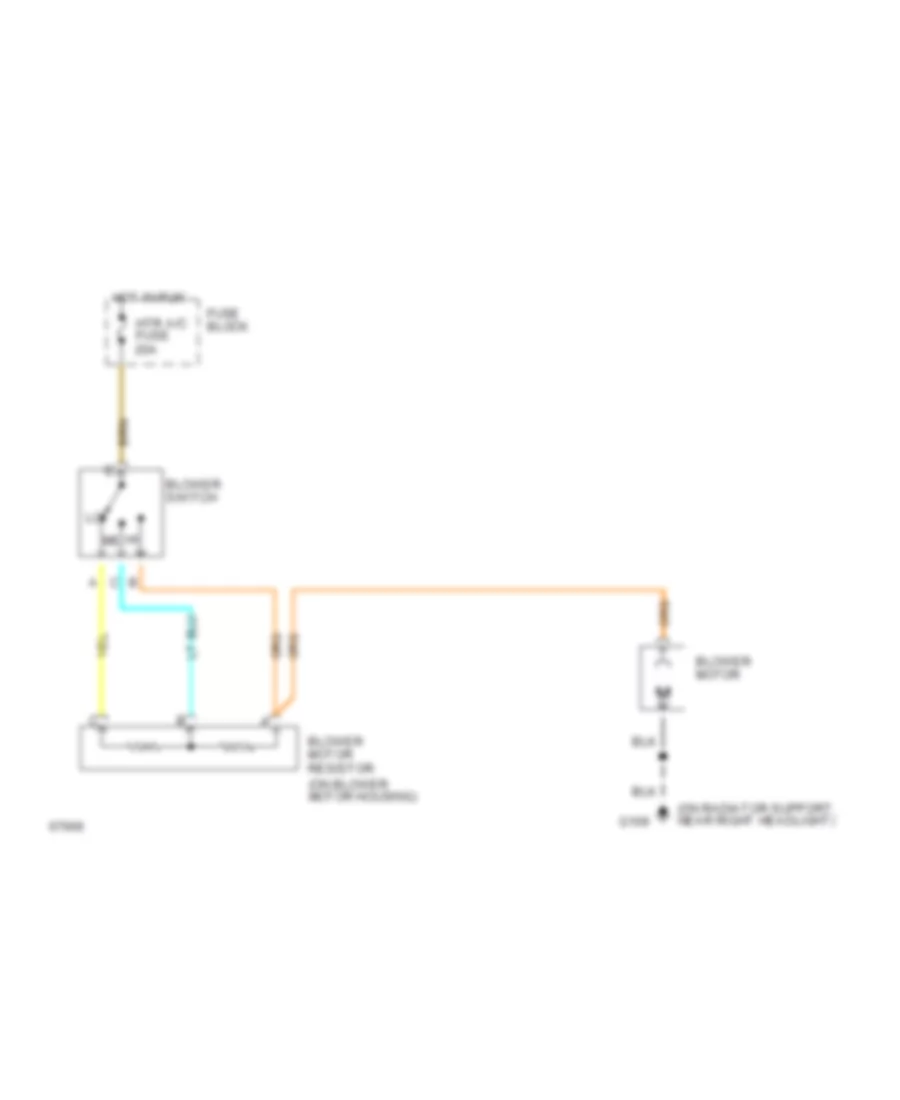
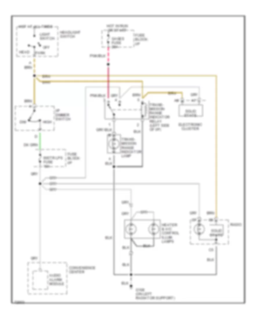
Heater Wiring Diagram for Chevrolet Astro 1995
List of elements for Heater Wiring Diagram for Chevrolet Astro 1995:
- (on radiator support, near right headlight)
- Blower motor
- Blower motor resistor (on blower motor housing)
- Blower switch
- Fuse block
- G109
- Hot in run
- Htr a/c fuse 20a
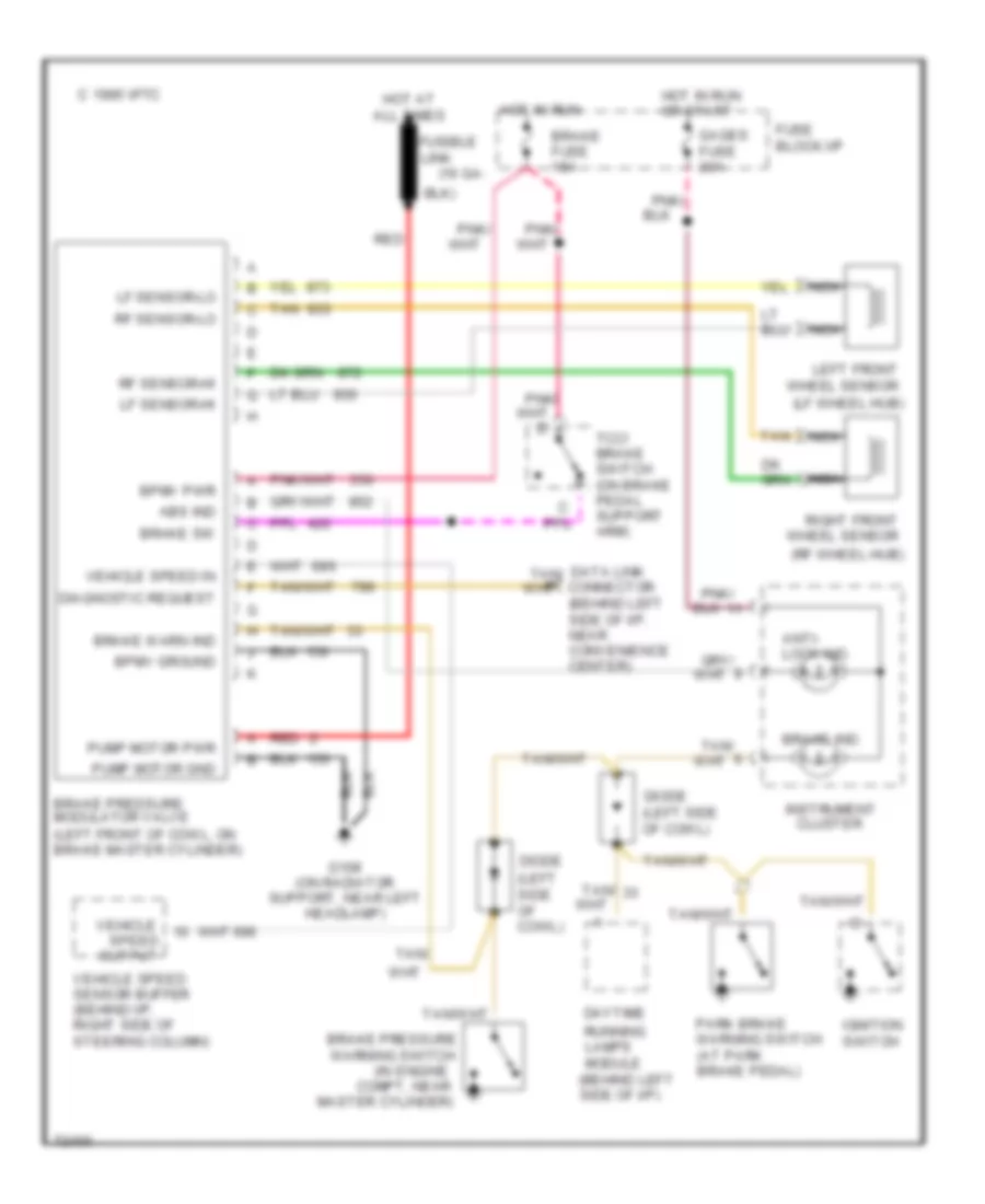
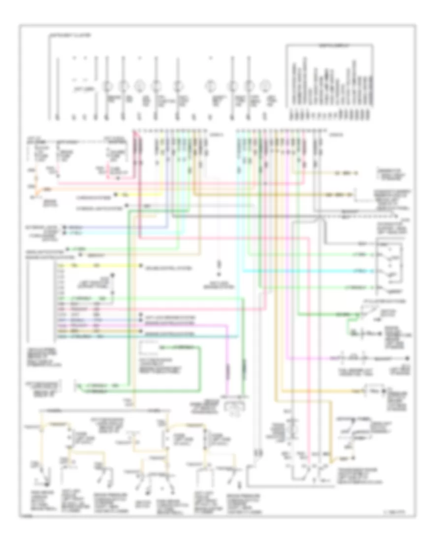
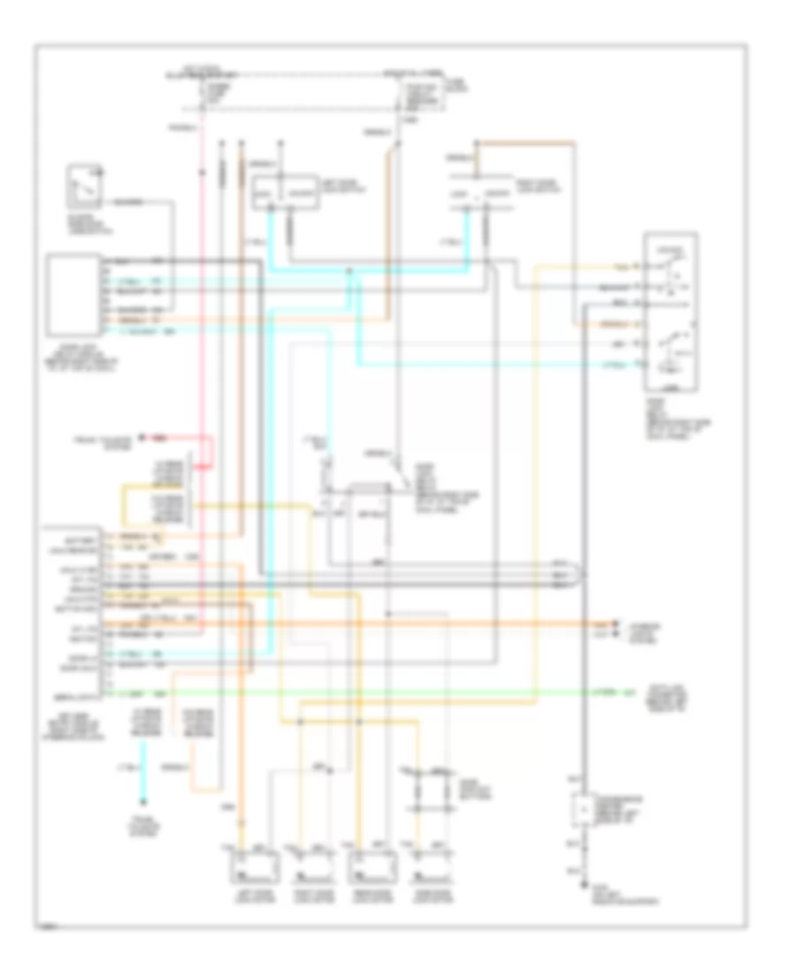
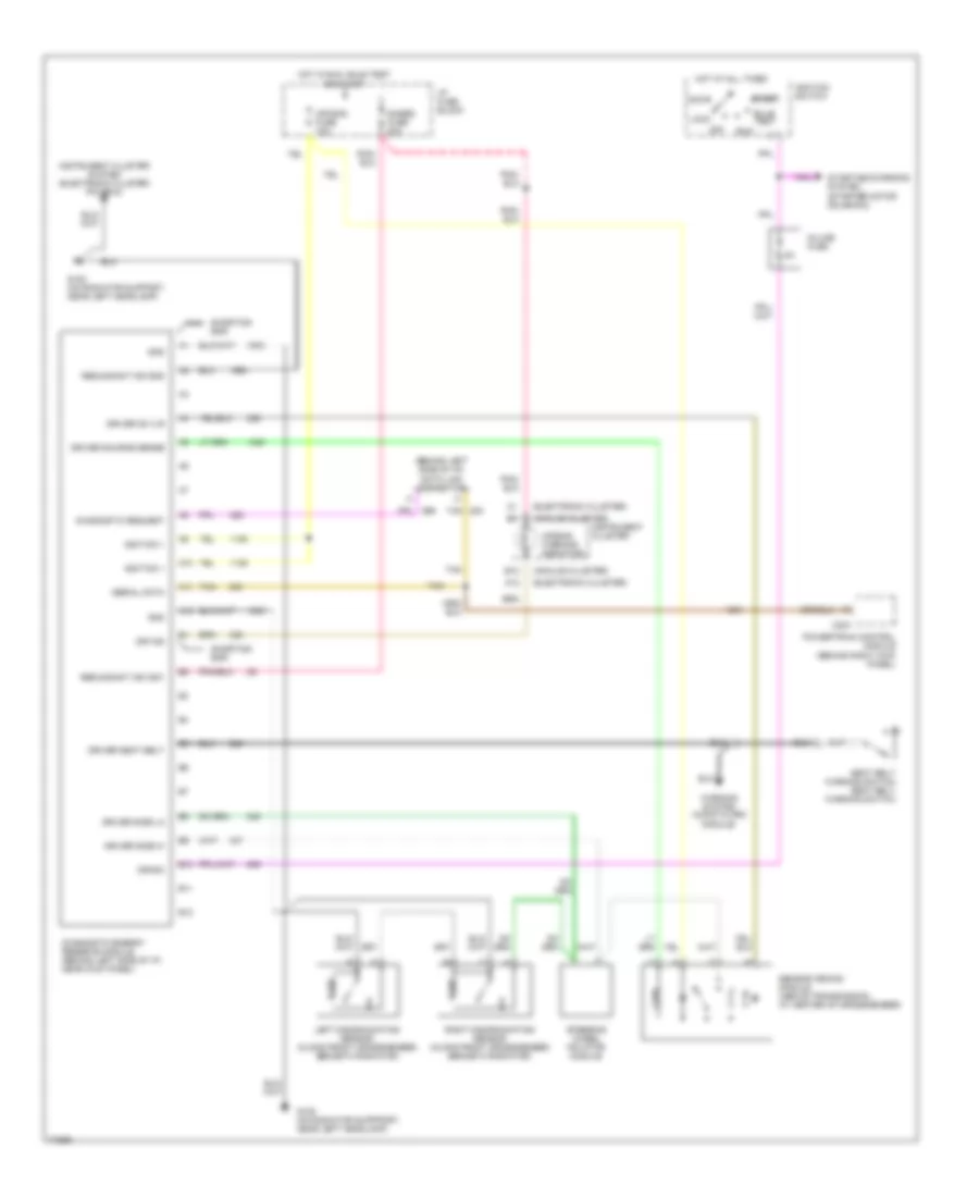
ANTI-LOCK BRAKES
Anti-lock Brake Wiring Diagrams for Chevrolet Astro 1995
List of elements for Anti-lock Brake Wiring Diagrams for Chevrolet Astro 1995:
- (16 ga-
- (behind left side of i/p)
- (in engine
- (lf wheel hub)
- (rf wheel hub)
- Abs ind
- Anti- lock ind.
- Bpmv ground
- Bpmv pwr
- Brake fuse 15a
- Brake ind.
- Brake pressure modulator valve (left front of cowl, on brake master cylinder)
- Brake pressure warning switch
- Brake sw
- Brake warn ind
- C 1995 vftc
- Cluster
- Compt, near
- Data link connector
- Daytime
- Diagnostic request
- Diode (left side of cowl)
- Fuse block:i/p
- Fusible
- G108 (on radiator support, near left headlamp)
- Gages fuse 20a
- Hot at all times
- Hot in run
- Hot in run or start
- Ignition switch
- Instrument
- Left front wheel sensor
- Lf sensor-hi
- Lf sensor-lo
- Link
- Master cylinder)
- Nca
- Output
- Park brake warning switch (at park brake pedal)
- Pnk/
- Pump motor gnd
- Pump motor pwr
- Red
- Rf sensor-hi
- Rf sensor-lo
- Right front wheel sensor
- Running lamps module
- Speed
- Tan
- Tan/
- Tcc/ brake switch (on brake pedal support arm)
- Vehicle
- Vehicle speed in
- Vehicle speed sensor buffer (behind i/p, right side of steering column)
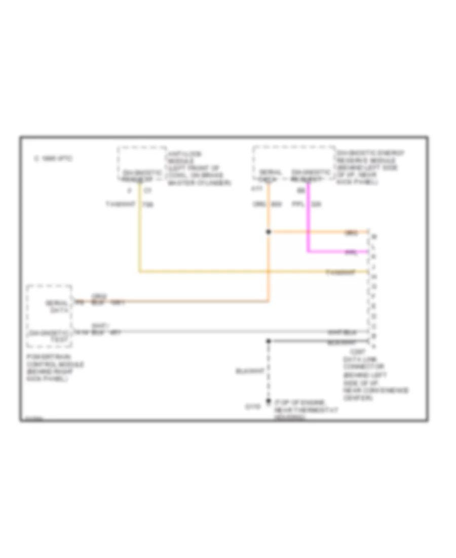
COMPUTER DATA LINES
Data Link Connector Wiring Diagram for Chevrolet Astro 1995
List of elements for Data Link Connector Wiring Diagram for Chevrolet Astro 1995:
- (behind left side of i/p, near convenience center)
- (top of engine, near thermostat housing)
- A11
- A14 diagnostic test
- Anti-lock module (left front of diagnostic cowl, on brake master cylinder)
- C 1995 vftc
- C297
- Data
- Data link connector
- Diagnostic energy reserve module (behind left side diagnostic of i/p, near kick panel)
- F9 serial data
- G110
- Powertrain control module (behind right kick panel)
- Request
- Serial
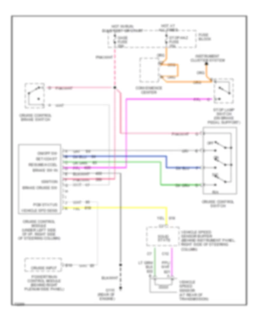
CRUISE CONTROL
Cruise Control Wiring Diagram for Chevrolet Astro 1995
List of elements for Cruise Control Wiring Diagram for Chevrolet Astro 1995:
- B10
- Brake cruise sw
- Brake sw in
- C12
- Column)
- Convenience center
- Cruise control brake switch
- Cruise control module (under left side of i/p, right side of steering column)
- Cruise control switch
- Cruise input
- Fuse block
- G115 (rear of engine)
- Gage fuse 20a
- Hot at all times
- Hot in run, bulb test or start
- Ignition
- Instrument cluster system
- Off
- On/off sw
- Pcm status
- Powertrain control module (behind right plenum side panel)
- R/a
- Resume/accel
- S/c
- Set/coast
- Solid state
- Stop lamp switch (on brake pedal support)
- Stop-haz fuse 15a
- Vehicle spd sens
- Vehicle speed sensor (at rear of transmission)
- Vehicle speed sensor buffer (behind instrument panel, right side of steering
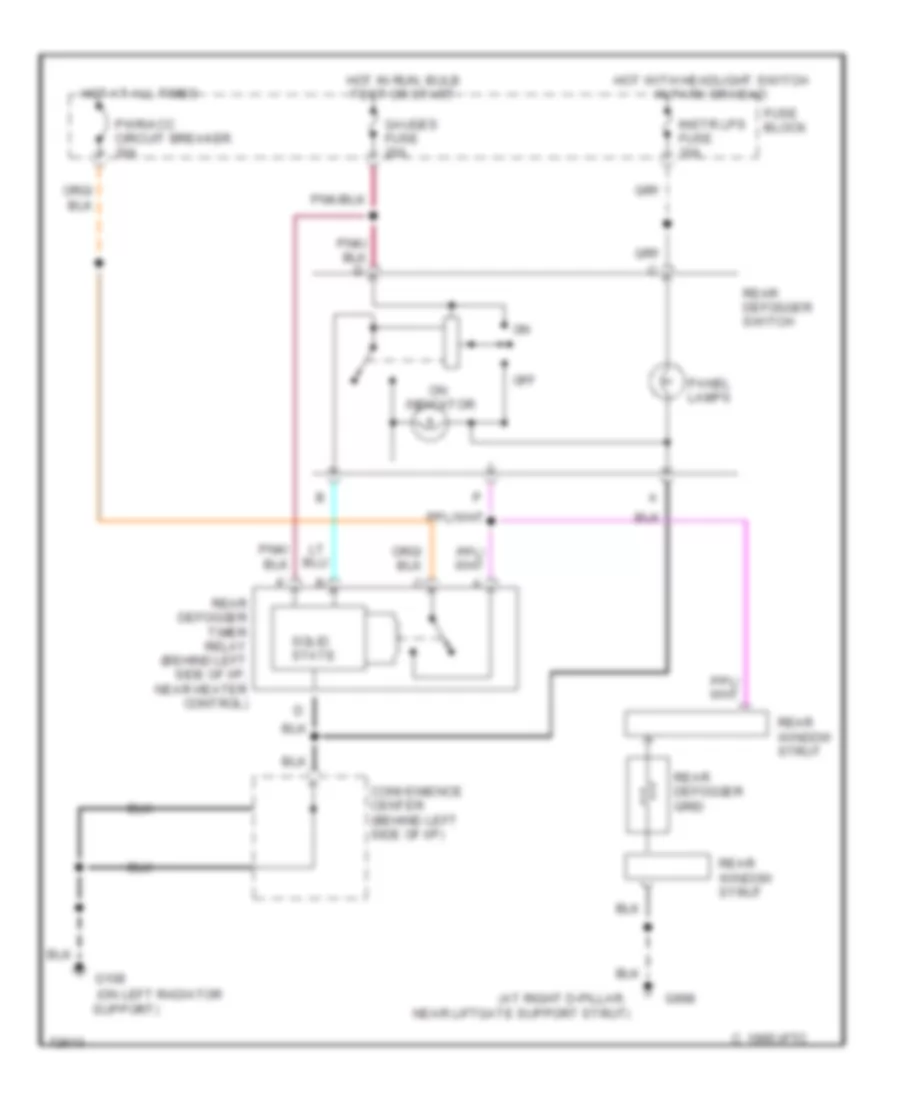
DEFOGGERS
Defogger Wiring Diagram for Chevrolet Astro 1995
List of elements for Defogger Wiring Diagram for Chevrolet Astro 1995:
- (at right d-pillar,
- (on left radiator
- C 1995 vftc
- Convenience center (behind left side of i/p)
- Fuse block
- G108
- G998
- Gauges fuse 20a
- Hot at all times
- Hot in run, bulb test or start
- Hot with headlight switch in park or head
- Indicator
- Instr lps fuse 10a
- Near liftgate support strut)
- Off
- Panel lamps
- Pwr/acc circuit breaker 30a
- Rear defogger grid
- Rear defogger switch
- Rear window strut
- Rear defogger timer relay (behind left side of i/p, near heater control)
- Solid state
- Support)
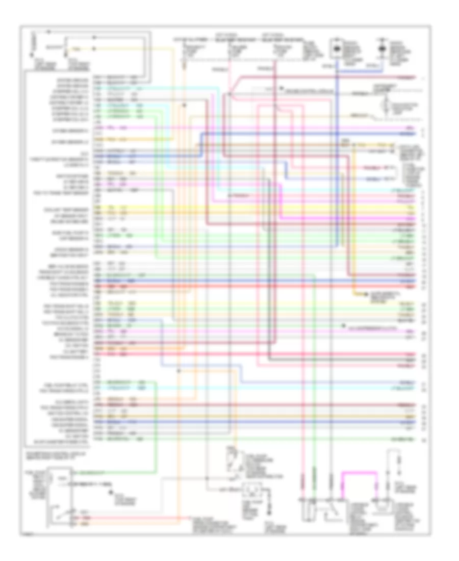
ENGINE PERFORMANCE
4.3L
4.3L (VIN W), Engine Performance Wiring Diagrams (1 of 2) for Chevrolet Astro 1995
List of elements for 4.3L (VIN W), Engine Performance Wiring Diagrams (1 of 2) for Chevrolet Astro 1995:
- 12v battery
- 12v ignition
- 5v return a
- 5v return b
- 5v sensor ref
- A/c compressor clutch
- A/c on signal in
- A10
- A11
- A12
- A13
- A14
- A15
- A16
- B10
- B11
- B12
- B13
- B14
- B15
- B16
- Brake sw to pcm
- Bulb test or start
- Coolant temp sensor
- Cruise control module
- Cruise ind reg grd
- Data link connector (behind left side of i/p)
- Distributor ref hi
- Distributor ref lo
- Dlc
- Dlc serial data
- E10
- E11
- E12
- E13
- E14
- E15
- E16
- Ecm/batt fuse 15a
- Ecm/ign fuse 10a
- Egr position input
- Egr valve solenoid
- Elec fuel pump in
- Evap canister purge ctrl
- F10
- F11
- F12
- F13
- F14
- F15
- F16
- Fuel injector (top of engine inside plenum)
- Fuel pump and sender (at fuel tank)
- Fuel pump prime connector (engine compartment on center of cowl)
- Fuel pump relay (right cowl, above blower motor)
- Fuel pump relay ctrl
- Fuel pump/ oil pressure switch (top rear of engine, near distributor)
- Fuse block (behind left side of i/p)
- G110 (top front of engine)
- G114 (left rear of engine)
- Gauges fuse 20a
- Hot at all times
- Hot in run,
- Iat sensor input
- Ignition bypass
- Ignition control (ic)
- Instrument cluster
- Knock sensor (rear of right cylinder head)
- Knock sensor (rear side of left cylinder head)
- Knock sensor in
- Lo side inj a
- Malfunction indicator lamp
- Map sensor in
- Mil indicator ctrl
- Oxygen sensor hi
- Oxygen sensor lo
- Pcm to trans temp sensor
- Pcm trans force mtr hi
- Pcm trans force mtr lo
- Pcm trans range a
- Pcm trans range b
- Pcm trans range c
- Pcm trans shift sol a
- Pcm trans shift sol b
- Pnk
- Powertrain control module (behind right side of i/p)
- Red
- Stepper coil a hi
- Stepper coil a lo
- Stepper coil b hi
- Stepper coil b lo
- System ground
- Tan
- Tcc clutch ctrl
- Tcc pwm solenoid ctrl
- Throttle position sensor in
- Trans shift 3/2 solenoid
- Variable tuning control relay (engine compartment, right side of cowl)
- Variable tuning control solenoid (center top of intake manifold)
- Variable tuning ctrl rly
- Vss buffer signal
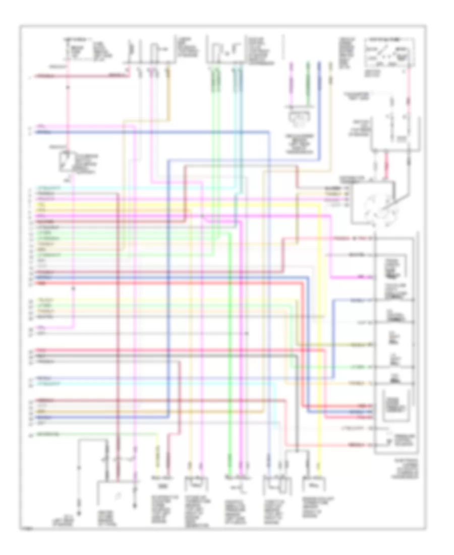
4.3L (VIN W), Engine Performance Wiring Diagrams (2 of 2) for Chevrolet Astro 1995
List of elements for 4.3L (VIN W), Engine Performance Wiring Diagrams (2 of 2) for Chevrolet Astro 1995:
- (front of engine)
- (left rear of engine)
- (top rear
- 1-2 shift sol
- 2-3 shift sol
- 3-2 control solenoid
- Accy
- Assembly
- Brake fuse 15a
- Bulb test
- C11
- C12
- C13
- Distributor
- Electronic 4-speed automatic overdrive transmission
- Engine coolant tmperature sensor
- Evaporative canister purge solenoid (top left side of engine)
- Fuse block (behind left side of i/p)
- G114
- Heated oxygen sensor (in y-pipe)
- Hot at all times
- Hot in run
- Idle air control valve (top front of engine near a/c compressor)
- Ignition coil
- Ignition switch
- Intake air tmperature sensor (top left front of engine, near generator)
- Linear egr solenoid (top front of engine)
- Lock
- Manifold absolute pressure sensor (left side of plenum)
- Nca
- Of engine)
- Off
- Pnk
- Pressure control solenoid
- Red
- Run
- Start
- Tachometer test lead
- Tan
- Tcc pulse width modulated solenoid
- Tcc sol
- Tcc/brake switch (on brake pedal support)
- Throttle position sensor (top left front of engine)
- Trans range press sw assembly
- Trans- mission fluid temp sensor
- Vehicle speed sensor (left rear side of transmission)
- Vehicle speed sensor buffer (behind right side of i/p)
EXTERIOR LIGHTS
Exterior Light Wiring Diagram for Chevrolet Astro 1995
List of elements for Exterior Light Wiring Diagram for Chevrolet Astro 1995:
- (left radiator support)
- (on brake pedal support bracket)
- (taped to body, near fuse block)
- Backup light switch (on steering column)
- Center high mount stop lamp
- Convenience center (behind left side of i/p)
- Electronic cluster
- Fuse block (left side of i/p)
- G108
- G108 (left radiator support)
- G109 (right radiator support)
- G998 (right d-pillar)
- G999 (left d-pillar)
- Hazard
- Hazard flasher
- Head
- Headlight switch
- Horn/ tl lps fuse 20a
- Hot at all times
- Hot in run or start
- In-line fuse 30a
- Instrument cluster
- Interior lights system
- Junction block (behind center of i/p)
- Left backup light
- Left front marker light
- Left front park/ turn light
- Left rear marker light
- Left tail/ stop/ turn light
- Left turn & hazard
- Left turn ind.
- License light
- Normal
- Off
- Optional
- Park
- Red
- Right backup light
- Right front marker light
- Right front park/ turn light
- Right rear marker light
- Right tail/ stop/ turn light
- Right turn & hazard
- Right turn ind.
- Stop -hz fuse 20a
- Stop lamp switch
- Turn b/u fuse 20a
- Turn flasher
- Turn- hazard switch
- W/optional trailer tow package
- Wire leads are spliced to trailer wiring, or connected to trailer wire plug
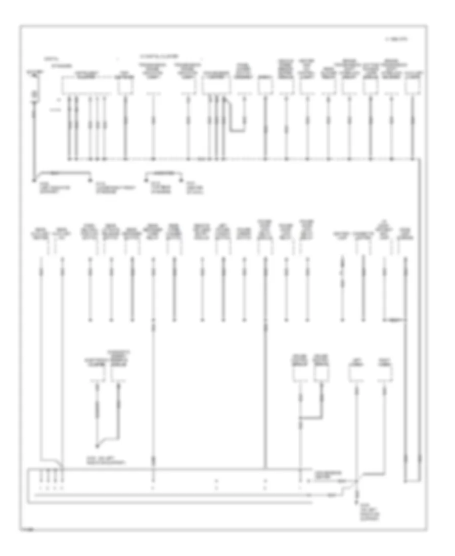
GROUND DISTRIBUTION
Ground Distribution Wiring Diagram (1 of 2) for Chevrolet Astro 1995
List of elements for Ground Distribution Wiring Diagram (1 of 2) for Chevrolet Astro 1995:
- (center of cowl)
- (on left
- (on left radiator
- A15
- Ashtray lamp
- Auxiliary lamps
- Battery
- Brake/
- C 1995 vftc
- C238
- Cigarette lighter
- Convenience center
- Cruise control module
- Cruise control servo
- Daytime running lamps module
- Diagnostic energy reserve module
- Digital
- Dome lamp overide
- Electronic cluster
- G108
- G108 (left radiator support)
- G108 radiator support)
- G115 (top rear of engine)
- G119 (lower right front of engine)
- G121
- Heater and a/c control lamp
- I/p comp- artment box lamp
- Instrument cluster
- Left horn
- Left power window switch
- Nca
- Panel dimmer switch assembly
- Park/ neutral position switch
- Power door lock delay module
- Power door lock delay relay
- Power door lock relay
- Power mirror switch
- Radio
- Rear auxiliary a/c
- Rear auxiliary heater
- Rear blower relay
- Rear defogger switch
- Rear defogger timer relay
- Rear liftgate release switch
- Rear wiper washer switch
- Remote keyless entry module
- Right horn
- Shift interlock relay
- Shift interlock solenoid
- Standard
- Support)
- Transmission
- Transmission range indicator lamp
- Trip switches
- Uncoated
- Vehicle speed sensor buffer module
- W/ digital cluster
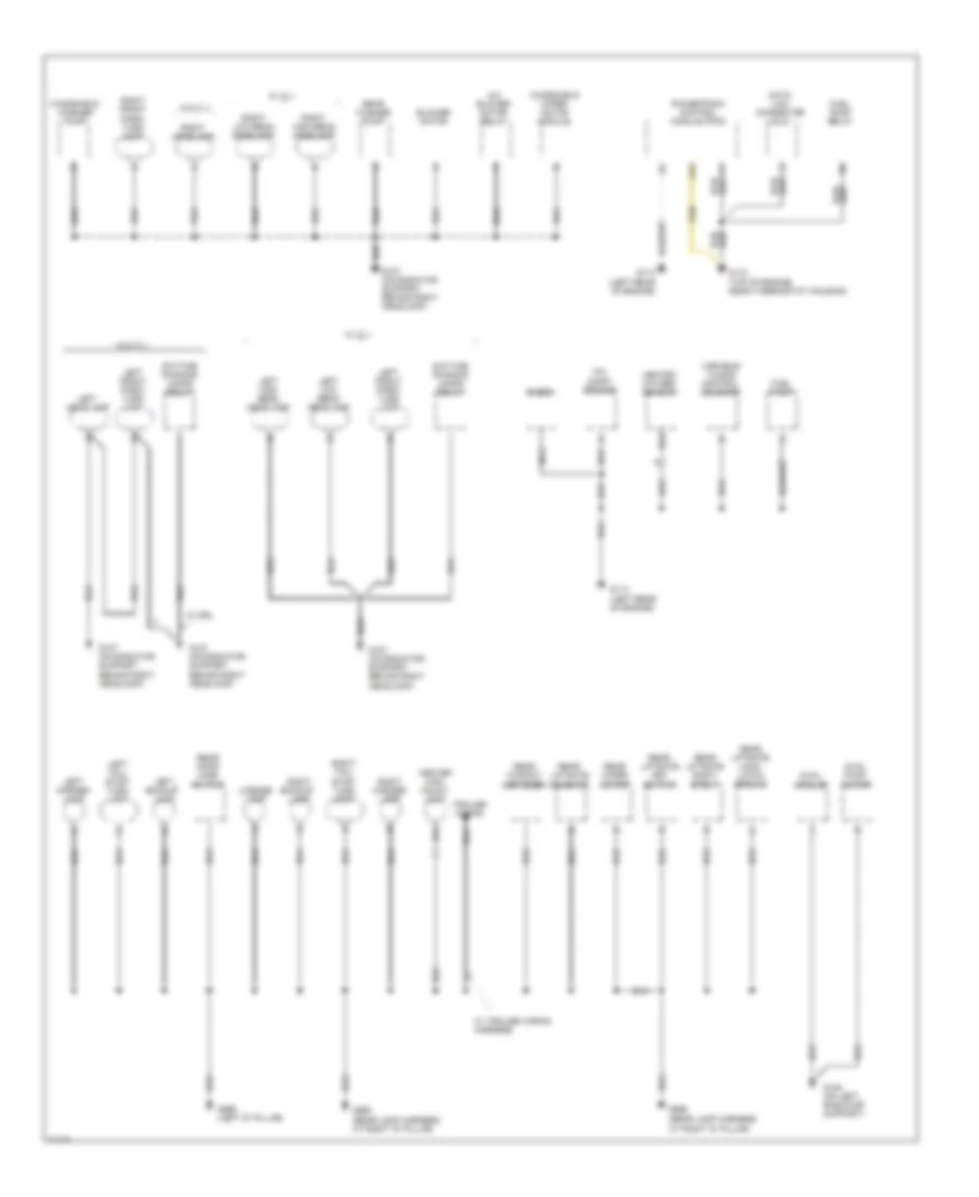
Ground Distribution Wiring Diagram (2 of 2) for Chevrolet Astro 1995
List of elements for Ground Distribution Wiring Diagram (2 of 2) for Chevrolet Astro 1995:
- (rear lamp harness at right "d" pillar)
- 4wal module
- 4wal pump motor
- A/c blower motor relay
- A/c comp- ressor
- A12
- Blower motor
- Center high mount lamp
- Data link connector (dlc)
- Daytime running lamps relay
- Diode
- Fuel pump
- Fuel pump relay
- G107 (on radiator support, behind right headlamp)
- G108 (on left radiator support)
- G110 (top of engine, near thermostat housing)
- G114 (left rear of engine)
- G998
- G998 (rear lamp harness at right "d" pillar)
- G999 (left "d" pillar)
- Heated oxygen sensor
- Left backup lamp
- Left front park/ turn lamp
- Left headlamp
- Left high beam headlamp
- Left low beam headlamp
- Left marker lamp
- Left tail/ stop- turn lamp
- License lamp
- Nca
- Powertrain control module (pcm)
- Rear door jamb switch
- Rear liftgate key switch
- Rear liftgate lock/ latch module
- Rear liftgate right strut
- Rear liftgate solenoid
- Rear washer pump
- Rear window defogger
- Rear wiper motor
- Right backup lamp
- Right front park/ turn lamp
- Right headlamp
- Right high beam headlamp
- Right low beam headlamp
- Right marker lamp
- Right tail/ stop- turn lamp
- Tan
- Trailer wiring
- Variable tuning control solenoid
- W/ drl
- W/ tl1
- W/ trailer wiring harness
- W/o tl1
- Windshield washer pump
- Windshield wiper motor module
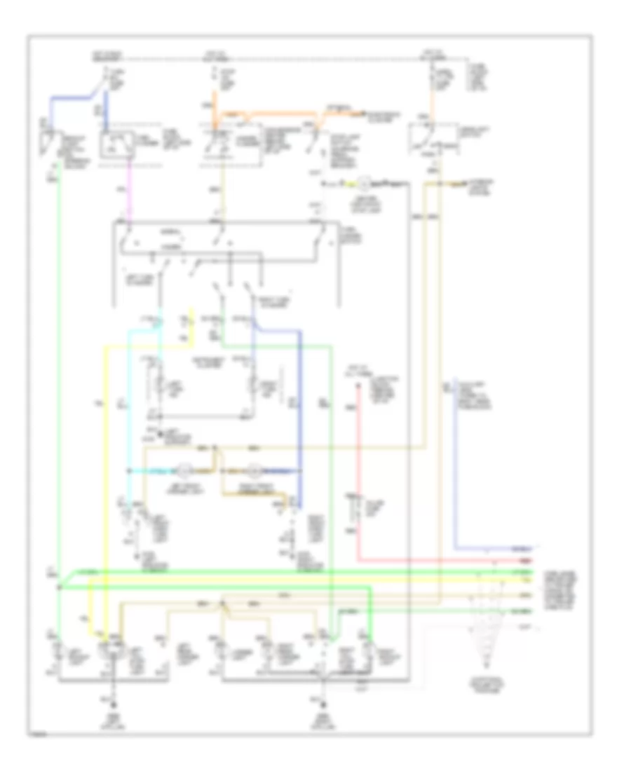
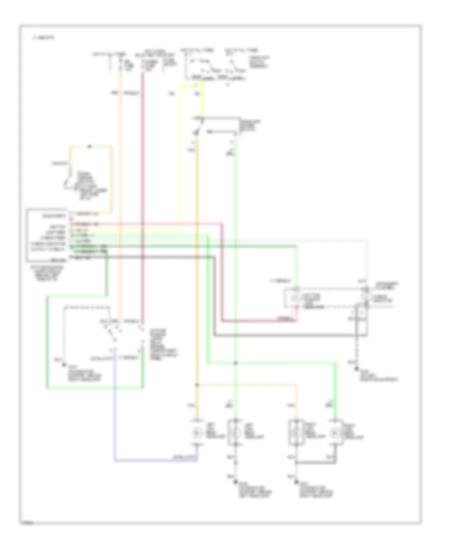
HEADLIGHTS
Headlight Wiring Diagram, Composite with DRL for Chevrolet Astro 1995
List of elements for Headlight Wiring Diagram, Composite with DRL for Chevrolet Astro 1995:
- Bulb check
- C 1995 vftc
- Daytime running lamp indicator
- Daytime running lamps module (behind left side of i/p)
- Daytime running lamps relay (engine compartment front plenum panel)
- Drl fuse 10a
- Fuse block
- G107 (on radiator support, behind right headlamp)
- G108 (on left radiator support)
- G108 (on radiator support, behind left headlamp)
- Gages fuse 20a
- Ground
- Head
- Headlamp dimmer switch
- Headlight switch assembly
- Hi beam feed
- Hi beam indicator
- Hot at all times
- Hot in run, bulb test or start
- Ignition
- Instrument cluster
- Lamp feed
- Left high beam headlamp
- Left low beam headlamp
- Off
- Output to relay
- Park
- Park brake switch (at park brake, under left side of i/p)
- Right high beam headlamp
- Right low beam headlamp
- Tan
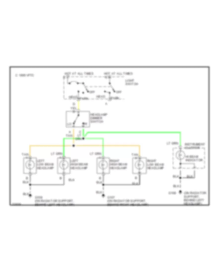
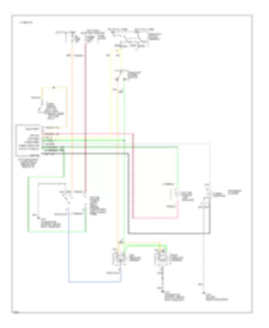
Headlight Wiring Diagram, Composite without DRL for Chevrolet Astro 1995
List of elements for Headlight Wiring Diagram, Composite without DRL for Chevrolet Astro 1995:
- (on radiator support, behind left headlamp)
- C 1995 vftc
- G107 (on radiator support, behind right headlamp)
- G108
- G108 (on radiator support, behind left headlamp)
- Head
- Headlamp dimmer switch
- Hi beam indicator
- Hot at all times
- Instrument cluster
- Left high beam headlamp
- Left low beam headlamp
- Light switch
- Off
- Park
- Right high beam headlamp
- Right low beam headlamp
- Tan
- Tan a
Headlight Wiring Diagram, Sealed Beam with DRL for Chevrolet Astro 1995
List of elements for Headlight Wiring Diagram, Sealed Beam with DRL for Chevrolet Astro 1995:
- Bulb check
- C 1995 vftc
- Daytime running lamp indicator
- Daytime running lamps module (behind left side of i/p)
- Daytime running lamps relay (engine compartment front plenum panel)
- Drl fuse 10a
- Fuse block
- G107 (on radiator support, behind right headlamp)
- G108 (on left radiator support)
- Gages fuse 20a
- Ground
- Head
- Headlamp dimmer switch
- Headlight switch assembly
- Hi beam feed
- Hi beam indicator
- Hot at all times
- Hot in run, bulb test or start
- Ignition
- Instrument cluster
- Lamp feed
- Left headlamp assembly
- Off
- Output to relay
- Park
- Park brake switch (at park brake, under left side of i/p)
- Right headlamp assembly
- Tan
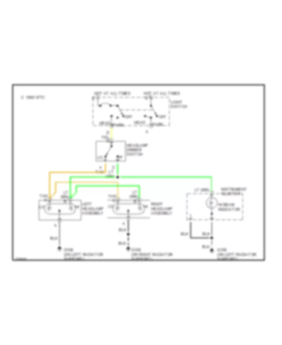
Headlight Wiring Diagram, Sealed Beam without DRL for Chevrolet Astro 1995
List of elements for Headlight Wiring Diagram, Sealed Beam without DRL for Chevrolet Astro 1995:
- C 1995 vftc
- G108 (on left radiator support)
- G109 (on right radiator support)
- Head
- Headlamp dimmer switch
- Hi beam indicator
- Hot at all times
- Instrument cluster
- Left hi headlamp assembly
- Light switch
- Off
- Park
- Right hi headlamp assembly
- Tan
- Tan c
HORN
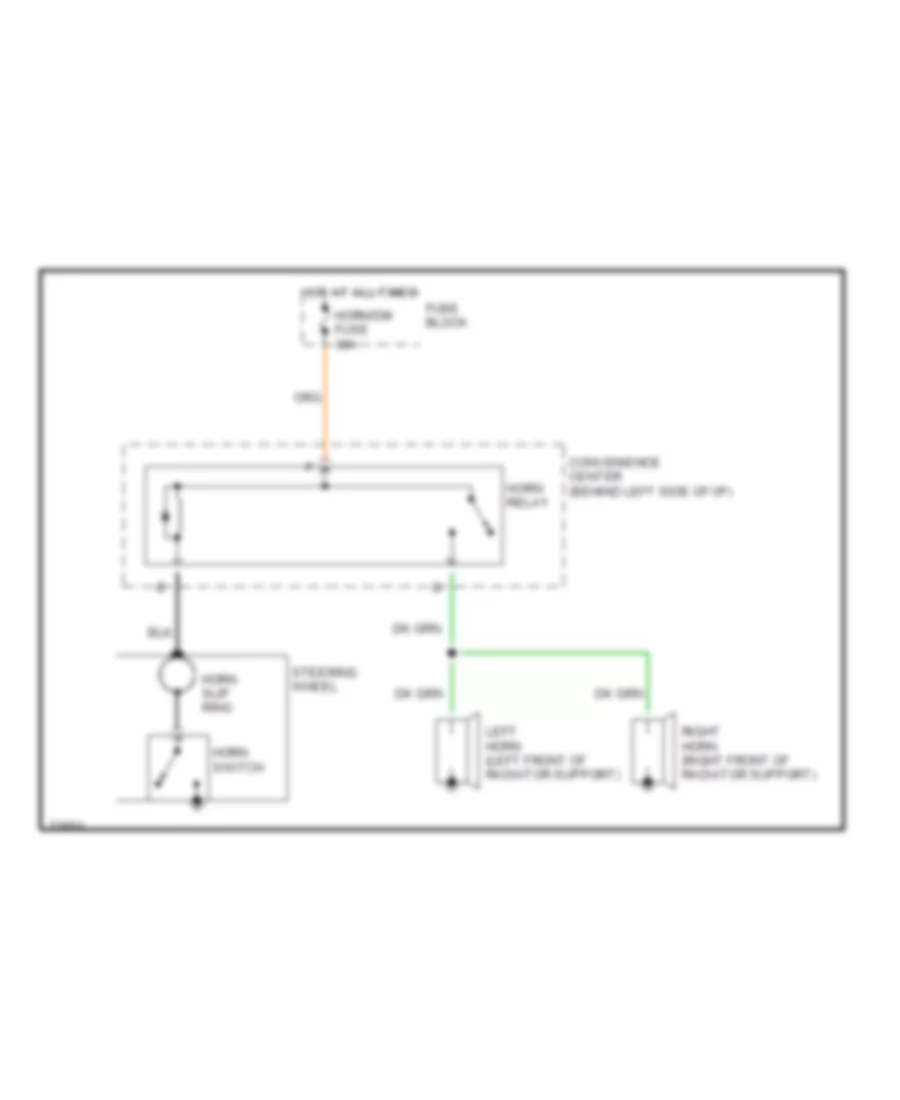
Horn Wiring Diagram for Chevrolet Astro 1995
List of elements for Horn Wiring Diagram for Chevrolet Astro 1995:
- Convenience center (behind left side of i/p)
- Fuse block
- Horn relay
- Horn slip ring
- Horn switch
- Horn/dm fuse 30a
- Hot at all times
- Left horn (left front of radiator support)
- Right horn (right front of radiator support)
- Steering wheel
INSTRUMENT CLUSTER
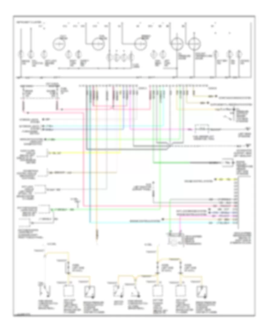
Instrument Cluster Wiring Diagram, Analog for Chevrolet Astro 1995
List of elements for Instrument Cluster Wiring Diagram, Analog for Chevrolet Astro 1995:
- (behind left
- (behind left side of i/p)
- (behind right
- (headlight
- (in engine compt front plenum panel)
- (left front of cowl, on
- (left rear of engine)
- (on radiator support, near left headlamp)
- (turn-hazard
- 1995 vftc c
- A11
- A12
- A13
- A14
- A15
- A16
- A17
- A18
- Air bag ind.
- Anti-lock
- Anti-lock brakes ind.
- Anti-lock brakes system
- Anti-lock module (left front of cowl, on brake master cylinder)
- Audio alarm
- B10
- B11
- B12
- B14
- Battery ind.
- Brake fuse 15a
- Brake ind.
- Brake master
- Brake pressure warning switch (in engine compt, near master cylinder)
- C10
- C11
- C12
- C13
- C14
- Center)
- Conn a
- Conn b
- Control module
- Convenience
- Coolant temperature gauge
- Cruise control system
- Cylinder)
- Daytime
- Daytime running
- Daytime running lamps relay
- Dimmer switch)
- Diode (left side of cowl)
- Drl ind.
- Engine controls system
- Engine coolant temperature sensor (left side of engine)
- Exterior lights
- Fuel gauge
- Fuel sender unit (inside fuel tank)
- Fuse block: i/p
- G108
- G108 (left radiator support panel)
- G114
- Gauges fuse 20a
- Headlights system
- High beam ind.
- Hot in run
- Ignition switch
- Illum. lamps
- Instrument cluster
- Interior lights
- Kick panel)
- Lamps module
- Left turn ind.
- Mal- function ind.
- Module
- Oil pressure gauge
- Oil pressure switch & sender (top rear of engine)
- Only
- Or start
- Park brake warning switch (at park brake pedal)
- Powertrain
- Right turn ind.
- Running lamps module (behind left side of i/p)
- Safety belt ind.
- Side of i/p, in
- Speedo- meter
- Starting/charging system
- Switch)
- System
- Tan
- Vehicle speed sensor (rear of transmission)
- Vehicle speed sensor buffer (behind i/p, right side of steering column)
- Volt- meter
- W/ drl
- W/o drl
Instrument Cluster Wiring Diagram, Digital for Chevrolet Astro 1995
List of elements for Instrument Cluster Wiring Diagram, Digital for Chevrolet Astro 1995:
- (at rear of
- (behind left side of i/p)
- (behind left side of i/p,
- (engine compartment front plenum panel)
- (not used)
- (on radiator support, near left headlamp)
- (right front
- (top rear of engine)
- (turn-hazard
- 1995 vftc c
- A10
- A11
- A12
- A13
- A14
- Air bag ind.
- Anti- lock ind.
- Anti-lock brakes system
- Anti-lock module (left front of cowl, on brake master cylinder)
- B10
- B11
- B12
- B13
- B15
- B16
- Battery
- Battery telltale
- Brake fuse 15a
- Brake ind.
- Brake pressure warning switch (in engine compt, near master cylinder)
- Brake switch
- C10
- C11
- C12
- C13
- C14
- Conn a
- Conn b
- Coolant temperature
- Cruise control system
- Daytime running
- Daytime running lamps relay
- Diagnostic energy
- Digital display
- Diode (left side of cowl)
- Drl ind.
- E/m
- Eng/metric switch
- Engine controls system
- Engine coolant temperature sensor (left side of engine)
- Exterior lights
- Fuel level
- Fuel sender unit (inside fuel tank)
- Fuse block:i/p
- G108
- G108 (left radiator support panel)
- G114 (left rear of engine)
- Gauges fuse 20a
- Generator
- Gnd
- Head
- Headlight switch assembly
- Headlights system
- High beam ind.
- Hot at all times
- Hot in run
- I/p cluster switches
- Ignition 3 (run)
- Ignition switch
- Instrument cluster
- Interior lights system
- Lamps module
- Left turn ind.
- Mal- function ind.
- Near kick panel)
- Of engine)
- Off
- Oil pressure
- Oil pressure switch & sender
- Or start
- Panel lamp dimmer
- Park
- Park brake warning switch (at park brake pedal)
- Park lamp switch
- Pnk/
- Power ground
- Reserve module
- Reset
- Right turn ind.
- Safety belt ind.
- Signal ground
- Speed sensor
- Stop/ hz fuse 20a
- Switch)
- System
- Tan
- Tan/
- Trans- mission range indicator lamp b
- Transmission range indicator relay (left side of i/p, near steering column)
- Transmission)
- Trip
- Trip reset switch
- Trip/season odo switch
- Vehicle
- Vehicle speed sensor buffer (behind i/p, right side of steering column)
- Vehicle speed signal
- W/ drl
- W/o drl
- Warning systems
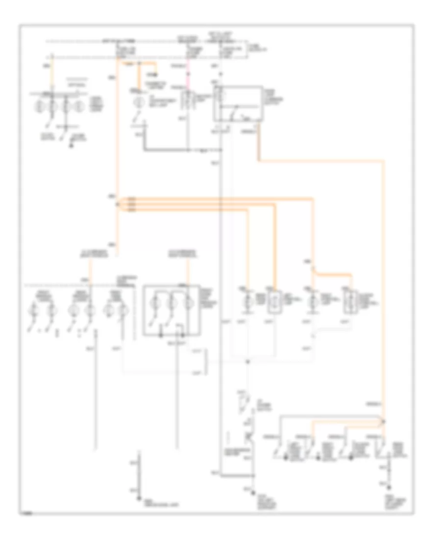
INTERIOR LIGHTS
Courtesy Lamps Wiring Diagram, with Auxiliary Lighting for Chevrolet Astro 1995
List of elements for Courtesy Lamps Wiring Diagram, with Auxiliary Lighting for Chevrolet Astro 1995:
- Ashtray lamp
- Cgr ltr/ dm fuse 20a
- Cigarette lighter
- Convenience center
- Cover switch
- Dome lamp override switch
- Front dome and reading lamps
- Front dome lamps
- Front reading lamps
- Fuse block:i/p
- G108 (on left radiator support)
- G404 (left rear of cargo compt)
- G908 (above dome lamp)
- Gages fuse 20a
- Hi/low switch
- Hot at all times
- Hot in run or start
- Hot w/ light switch in park or head
- I/p compartment box lamp
- I/p dimmer switch
- Instr-lps fuse 10a
- Left front door jamb switch
- Left stepwell lamp
- Nca
- Off
- Optional
- Overhead roof console
- Rear dome lamp
- Rear door jamb switch
- Rear reading lamps
- Right front door jamb switch
- Right stepwell lamp
- Sliding door jamb switch
- Sliding door stepwell lamp
- Visor/ vanity mirror lamps
- W/ overhead roof console
- W/o overhead roof console
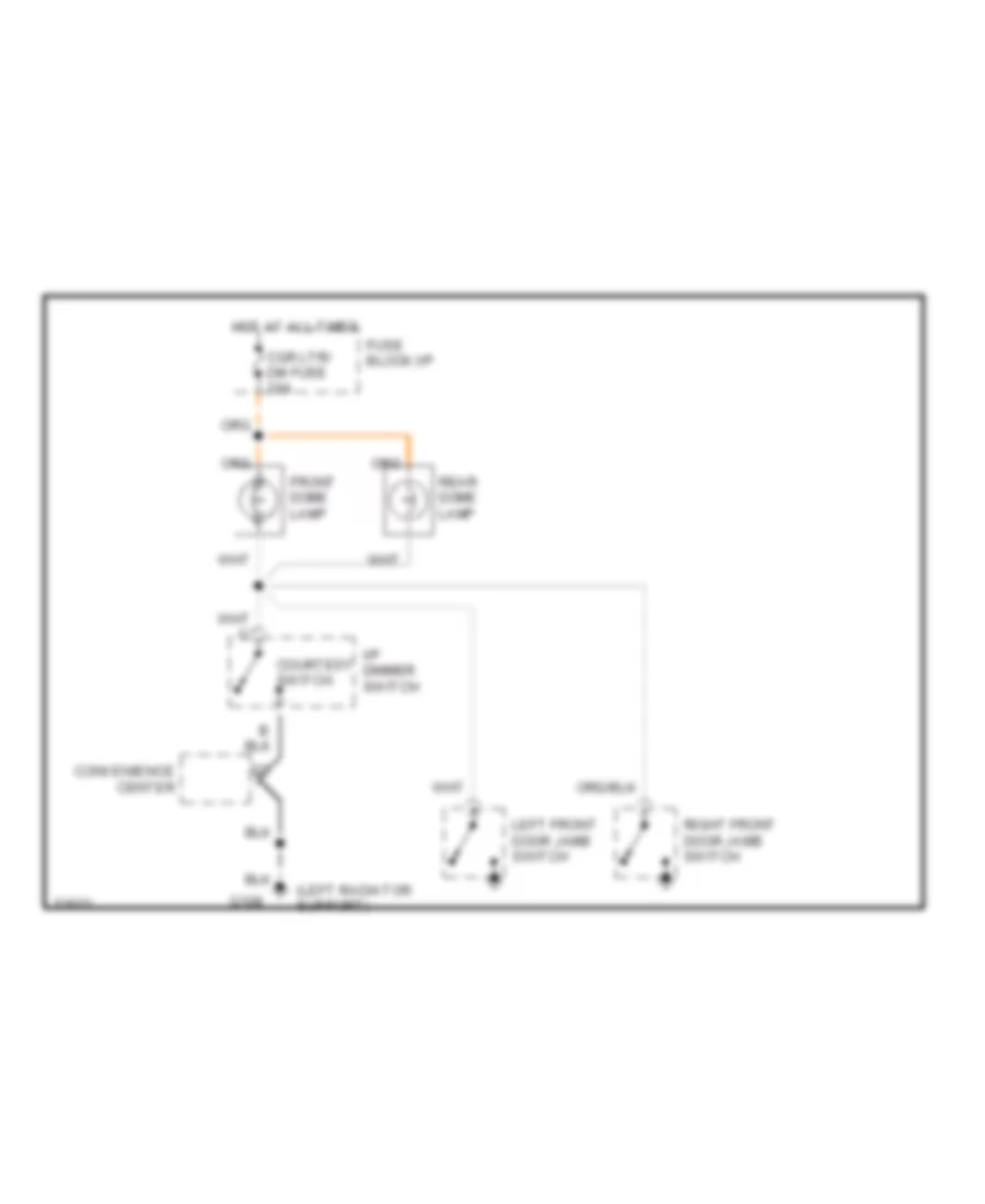
Courtesy Lamps Wiring Diagram, without Auxiliary Lighting for Chevrolet Astro 1995
List of elements for Courtesy Lamps Wiring Diagram, without Auxiliary Lighting for Chevrolet Astro 1995:
- (left radiator support)
- Cgr ltr/ dm fuse 20a
- Convenience center
- Courtesy switch
- Front dome lamp
- Fuse block:i/p
- G108
- Hot at all times
- I/p dimmer switch
- Left front door jamb switch
- Rear dome lamp
- Right front door jamb switch
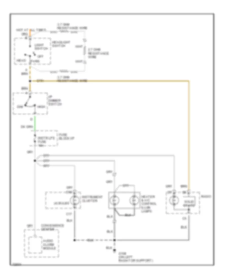
Instrument Illumination Wiring Diagram, Analog Cluster for Chevrolet Astro 1995
List of elements for Instrument Illumination Wiring Diagram, Analog Cluster for Chevrolet Astro 1995:
- (4) bulbs
- 2.7 ohm resistance wire
- 3.7 ohm resistance wire
- Audio alarm module
- C17
- C18
- Convenience center
- Dim
- Fuse block:i/p
- G108 (on left radiator support)
- Head
- Headlight switch
- Heater & a/c control illum. lamps
- High
- Hot at all times
- I/p dimmer switch
- Instr lps fuse 10a
- Instrument cluster
- Light switch
- Off
- Park
- Radio
- Solid state
Instrument Illumination Wiring Diagram, Digital Cluster for Chevrolet Astro 1995
List of elements for Instrument Illumination Wiring Diagram, Digital Cluster for Chevrolet Astro 1995:
- Audio alarm module
- Convenience center
- Dim
- Electronic cluster
- Fuse block:
- G108 (on left radiator support)
- Gages fuse 20a
- Head
- Headlight switch
- Heater & a/c control illum. lamps
- High
- Hot at all times
- Hot in run or start
- I/p
- I/p dimmer switch
- Instr lps fuse 10a
- Light switch
- Off
- Park
- Radio
- Solid state
- Trans- mission range indicator lamp
- Trans- mission range indicator relay (left side of i/p)
POWER DISTRIBUTION
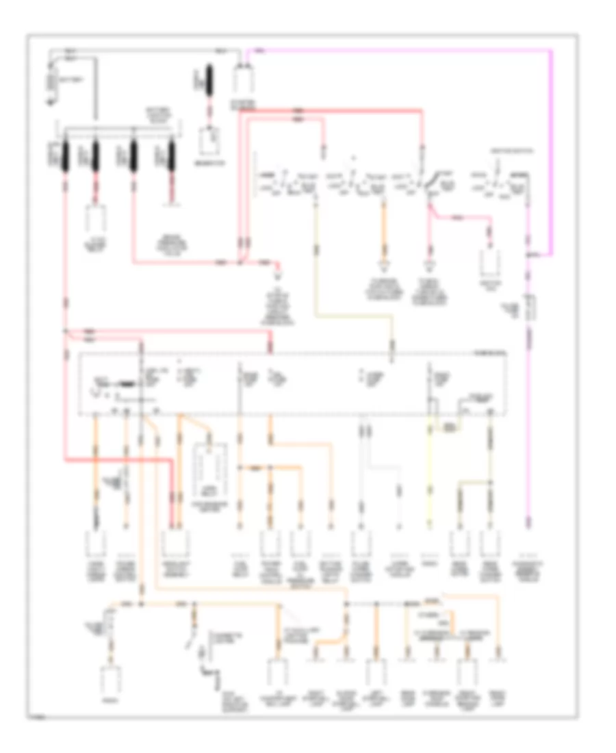
Power Distribution Wiring Diagram (1 of 2) for Chevrolet Astro 1995
List of elements for Power Distribution Wiring Diagram (1 of 2) for Chevrolet Astro 1995:
- Accy
- B10
- Base
- Bat
- Batt bus
- Battery
- Battery junction block
- Brake pressure modulator valve
- Bulb test
- Bus
- C198 fusible
- C3 a
- Cgr ltr/ dm fuse 20a
- Cigarette lighter
- Coil
- Convenience center
- Daytime running
- Diagnostic
- Drl fuse 10a
- E16
- Ecmb fuse 15a
- Energy reserve module
- Front dome and reading lamp
- Front dome lamp
- Fuel pump relay
- Fuel pump/ oil pressure switch
- Fuse block
- Fusible
- G108 (on left radiator support)
- Generator
- Headlight switch assembly
- Hi a/c blower relay
- Horn relay
- Hrn/tl lps fuse 20a
- I/p compartment box lamp
- Ignition
- Ignition switch
- In-line fuse 10a
- In-line fuse 3a
- In-line fuse 5a
- Left stepwell lamp
- Lights relay
- Link rust
- Link a
- Link b
- Link c
- Link d
- Lock
- Nca
- Off
- Others
- Overhead roof console
- Pnk
- Power mirror control switch
- Power- train control module
- Pulse wiper/ washer switch
- Pwr acc
- Radio
- Radio fuse 15a
- Rear dome lamp
- Rear wiper motor
- Rear wiper washer switch
- Red
- Right stepwell lamp
- Run
- Rust
- Shunt
- Sliding door stepwell lamp
- Start
- Starter solenoid
- To stop-hz fuse & pwr acc circuit breaker (fuse block)
- To brake, pwr wdo & htr a/c fuses (fuse block)
- To emci, airbag, turn b/u & gages fuses (fuse block)
- Visor/ vanity mirror lamps
- W/ auxilliary lighting package
- W/ overhead console
- W/ reading lamps
- Wiper fuse 25a
- Wiper motor and module
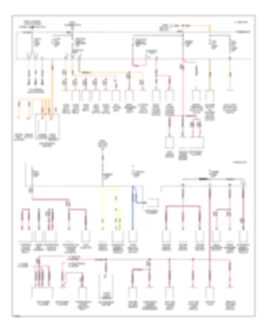
Power Distribution Wiring Diagram (2 of 2) for Chevrolet Astro 1995
List of elements for Power Distribution Wiring Diagram (2 of 2) for Chevrolet Astro 1995:
- (panel dimmer switch)
- A10
- Air bag fuse 10a
- Ashtray lamp
- Audio alarm module
- Aux htr a/c fuse 25a
- Auxilliary heater and a/c blower motor
- Blower switch or blower motor control switch
- Brake fuse 15a
- Brake pressure modulator valve
- Brake switch
- C 1995 vftc
- Convenience center
- Cruise brake module
- Cruise brake switch
- Cruise control switch
- Daytime running lamps module
- Daytime running lamps relay
- Diagnostic energy reserve module
- Door lock delay module
- Door lock delay relay
- Door lock relay
- E15
- Ecm i fuse 10a
- Electronic 4-speed overdrive transmission
- Evaporative canister purge solenoid
- F15
- From c ignition switch
- From fusible link b
- From ignition switch
- From interior lights system
- Fuel injector
- Fuse block
- Gages fuse 20a
- Hazard flasher
- Heated oxygen sensor
- Htr a/c fuse 20a
- Ign bus
- Instr lps fuse 10a
- Instru- ment cluster
- Instrument cluster
- Left door lock switch
- Left power seat
- Left power window master switch
- Liftgate lock/ latch module
- Linear egr solenoid
- Park/ neutral position switch
- Pnk
- Pnk/
- Powertrain control module
- Pwr acc bus
- Pwr acc circuit breaker 30a
- Pwr wdo bus
- Pwr wdo circuit breaker 30a
- Rear defogger switch
- Rear defogger timer delay
- Rear defogger timer relay
- Red
- Remote keyless entry module
- Right door lock switch
- Right front power window switch
- Sensor arming module
- Shunt
- Stop- haz fuse 20a
- Tcc/ brake switch
- To interior lights system
- Transmission range indicator relay
- Turn b/u fuse 20a
- Turn signal flasher
- Variable tuning control relay
- Vehicle speed sensor buffer
- W/ analog cluster
- W/ electronic cluster
- W/ gage cluster
POWER DOOR LOCKS
Door Lock Wiring Diagram for Chevrolet Astro 1995
List of elements for Door Lock Wiring Diagram for Chevrolet Astro 1995:
- C292
- Convenience center (behind left side of i/p)
- Door contact buttons
- Door lock delay module (behind right side of i/p, at top of cowl)
- Door lock delay relay (behind right side of i/p, at top of cowl panel)
- Door lock relay (behind right side of i/p, at top of cowl panel)
- Fuse block
- G108 (on left radiator support)
- Hot at all times
- Left door lock motor
- Left door lock switch
- Lock
- Pwr acc circuit breaker 30a
- Rear door lock motor
- Right door lock motor
- Right door lock switch
- Side door lock motor
- Sliding side door jamb switch (on right "b" pillar)
- Tan
- Unlock
Keyless Entry Wiring Diagram for Chevrolet Astro 1995
List of elements for Keyless Entry Wiring Diagram for Chevrolet Astro 1995:
- (or red)
- Batt/r wdo
- Battery
- C292
- Convenience center (behind left side of i/p)
- Data link connector (behind left side of i/p)
- Door contact buttons
- Door lk
- Door lock delay module (behind right side of i/p, at top of cowl)
- Door lock delay relay (behind right side of i/p, at top of cowl panel)
- Door lock relay (behind right side of i/p, at top of cowl panel)
- Door unlk
- Fuse block
- G108 (on left radiator support)
- Gages fuse 20a
- Ground
- Hot at all times
- Hot in run, bulb test or start
- Ignition
- Int lts
- Interior lights system
- Keyless entry module (right side of steering column)
- Left door lock motor
- Left door lock switch
- Lock
- Pwr acc circuit breaker 30a
- Rear door lock motor
- Red
- Right door lock motor
- Right door lock switch
- Serial data
- Side door lock motor
- Sliding side door jamb switch
- Tan
- Trunk, tailgate system
- Unlk lf dr
- Unlk mtr
- Unlk rear dr
- Unlock
- W/ rear liftgate window release
- W/o rear liftgate window release
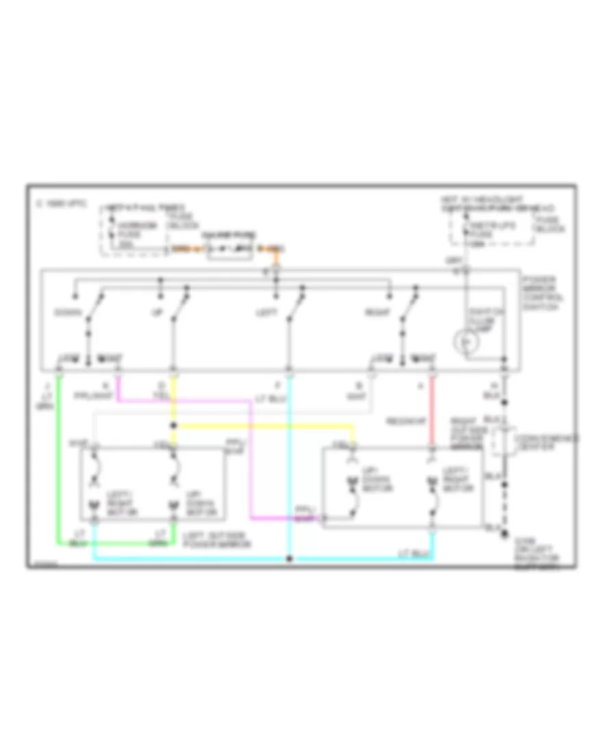
POWER MIRRORS
Power Mirror Wiring Diagram for Chevrolet Astro 1995
List of elements for Power Mirror Wiring Diagram for Chevrolet Astro 1995:
- C 1995 vftc
- Convenience center
- Down
- Fuse block
- G108 (on left radiator support)
- Horn/dm fuse 30a
- Hot at all times
- Hot w/ headlight switch in park or head
- In-line fuse
- Instr lps fuse 30a
- Left
- Left outside power mirror
- Left/ right motor
- Power mirror control switch
- Right
- Right outside power mirror
- Switch illum lamp
- Up/ down motor
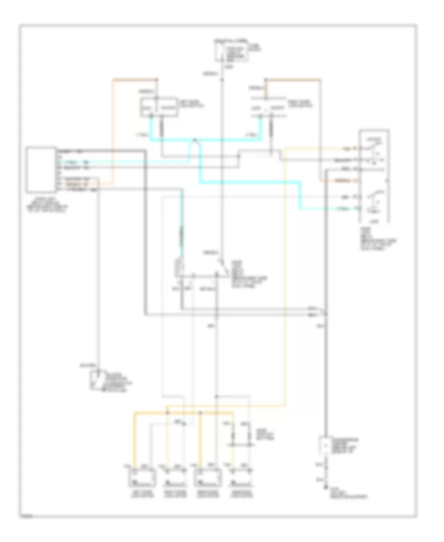
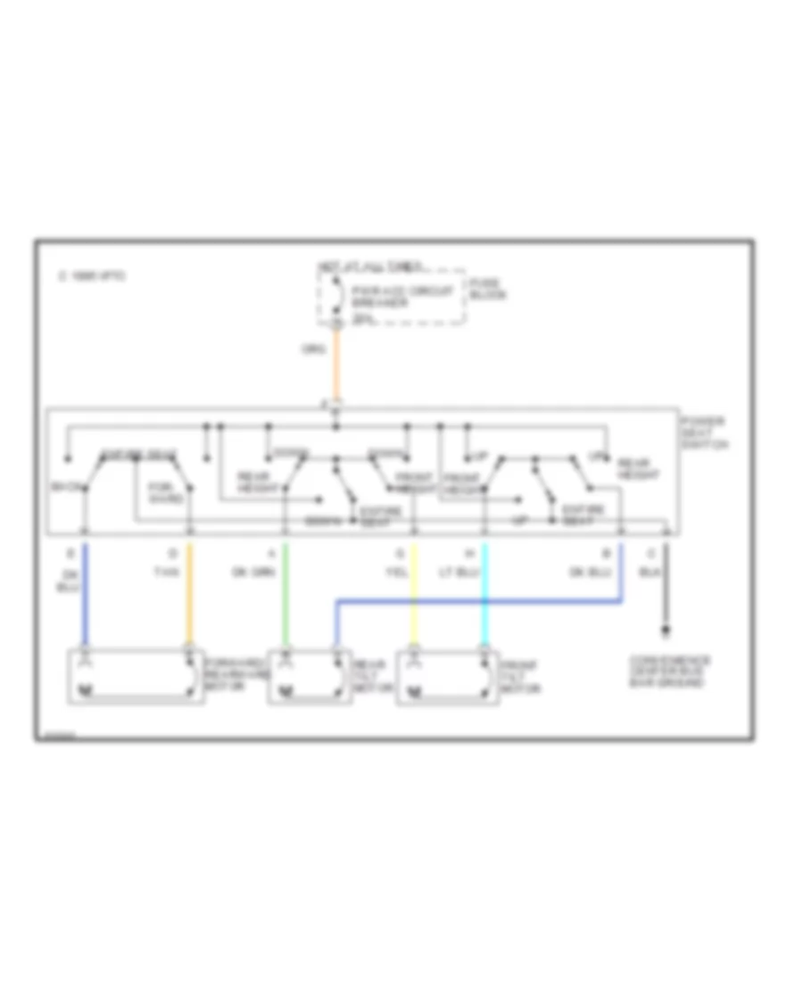
POWER SEATS
Power Seat Wiring Diagrams for Chevrolet Astro 1995
List of elements for Power Seat Wiring Diagrams for Chevrolet Astro 1995:
- 30a
- Back
- C 1995 vftc
- Convenience center bus bar ground
- Down
- Entire seat
- For- ward
- Forward/ rearward motor
- Front height
- Front tilt motor
- Fuse block
- Hot at all times
- Power seat switch
- Pwr acc circuit breaker
- Rear height
- Rear tilt motor
- Tan
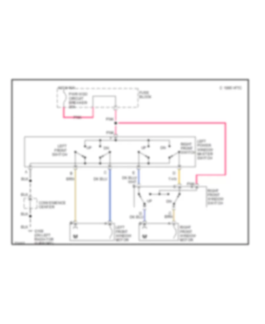
POWER WINDOWS
Power Window Wiring Diagram for Chevrolet Astro 1995
List of elements for Power Window Wiring Diagram for Chevrolet Astro 1995:
- C 1995 vftc
- Convenience center
- Fuse block
- G108 (on left radiator support)
- Hot in run
- Left front switch
- Left front window motor
- Left power window master switch
- Pnk
- Pnk a
- Pwr wdo circuit breaker 30a
- Right front switch
- Right front window motor
- Right front window switch
- Tan
RADIO
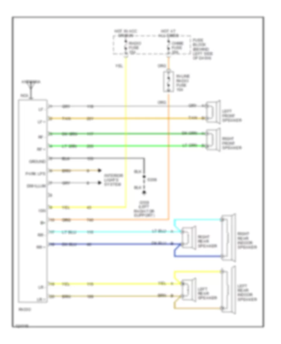
Radio Wiring Diagrams for Chevrolet Astro 1995
List of elements for Radio Wiring Diagrams for Chevrolet Astro 1995:
- Antenna
- B+ b+
- Chime fuse 30a
- Dim illum
- Fuse block (behind left side of dash)
- G108 (left radiator support)
- Ground
- Hot at all times
- Hot in acc or run
- Ign
- In-line radio fuse 10a
- Interior lights system
- Left front speaker
- Left rear indoor speaker
- Left rear speaker
- Lf +
- Lf -
- Lr +
- Lr -
- Nca
- Park lps
- Radio
- Radio fuse 15a
- Rf +
- Rf -
- Right front speaker
- Right rear indoor speaker
- Right rear speaker
- Rr +
- Rr -
- S208
- Tan
SHIFT INTERLOCKS
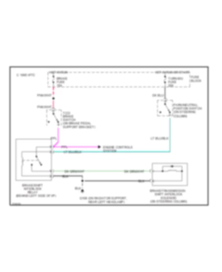
Shift Interlock Wiring Diagram for Chevrolet Astro 1995
List of elements for Shift Interlock Wiring Diagram for Chevrolet Astro 1995:
- (behind left side of i/p)
- Brake fuse 15a
- Brake/shift interlock relay
- Brake/transmission shift interlock solenoid (on steering column)
- C 1995 vftc
- Column)
- Engine controls system
- Fuse block
- G108 (on radiator support, near left headlamp)
- Hot in run
- Hot in run or start
- Park/neutral position switch (on steering
- Tcc/ brake switch (on brake pedal support bracket)
- Turn b/u fuse 20a
STARTING/CHARGING
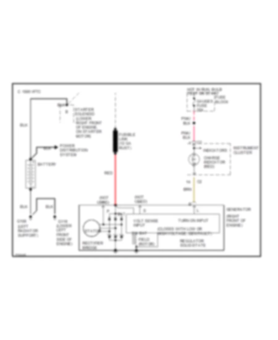
Charging Wiring Diagram for Chevrolet Astro 1995
List of elements for Charging Wiring Diagram for Chevrolet Astro 1995:
- (closes with low or high voltage; gen fault)
- (left radiator support)
- (not used)
- (right front of engine)
- Bat
- Battery
- C 1995 vftc
- Charge indicator (red)
- Field (rotor)
- Front side of engine)
- Fuse block
- Fusible link (12 ga. rust)
- G108
- G119 (lower left
- Gauges fuse 20a
- Generator
- Hot in run, bulb test or start
- Indicators
- Instrument cluster
- Power distribution system
- Rectifier bridge
- Red
- Regulator solid-state
- Starter solenoid (lower right front of engine, on starter motor)
- Stator
- Sw bat
- Turn on input
- Volt sense input
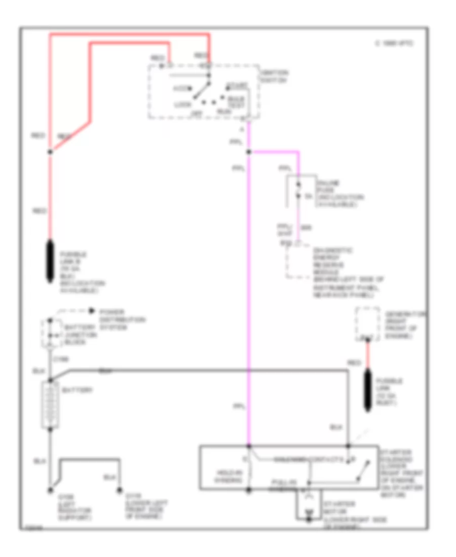
Starting Wiring Diagram for Chevrolet Astro 1995
List of elements for Starting Wiring Diagram for Chevrolet Astro 1995:
- (lower right side of engine)
- Accy
- B solenoid contacts
- B10
- Bat
- Battery
- Battery junction block
- Bulb test
- C 1995 vftc
- C198
- Diagnostic energy reserve module (behind left side of
- Fusible link (12 ga. rust)
- G108 (left radiator support)
- G119 (lower left front side of engine)
- Generator (right front of engine)
- Hold-in winding
- Ignition switch
- In-line fuse (no location available)
- Instrument panel, near kick panel)
- Lock
- Off
- Power distribution system
- Pull-in winding
- Red
- Run
- Start
- Starter motor
- Starter solenoid (lower right front of engine, on starter motor)
SUPPLEMENTAL RESTRAINTS
Supplemental Restraint Wiring Diagram for Chevrolet Astro 1995
List of elements for Supplemental Restraint Wiring Diagram for Chevrolet Astro 1995:
- (analog cluster)
- (behind left side of i/p) data link connector
- (electronic cluster)
- 2.49k
- 5.1k
- 8.45k
- A10
- A11
- A12
- Accy
- Air bag fuse 10a
- Air bag warning indicator
- B10
- B11
- B12
- Bulb test
- C204
- Crank
- Diagnostic energy reserve module (behind left side of i/p, near kick panel)
- Diagnostic request
- Driver 36 vlr
- Driver seat belt
- Driver side hi
- Driver side lo
- Driver source sense
- G108 (on radiator support, near left headlamp)
- G108 (on radiator suppport, near left headlamp)
- Gages fuse 20a
- Gnd
- Hot at all times
- Hot in run, bulb test or start
- I/p fuse block
- Ignition 1
- Ignition switch
- In-line fuse
- Instrument cluster
- Instrument cluster system (electronic cluster pin #b15)
- Left discriminating sensor (along front crossmember, benaeth radiator)
- Lock
- Off
- Powertrain control module (behind right kick panel)
- Redundant ind gnd
- Redundant ind ign1
- Right discriminating sensor (along front crossmember, benaeth radiator)
- Run
- Seat belt warning switch seat belt warning switch
- Sensor arming module (above transmission, at center of crossmember)
- Serial data
- Shorting bar
- Sir ind
- Start
- Starting/charging system (starter motor solenoid)
- Steering wheel inflator module
- Tan
- Warning system (audio alarm module)
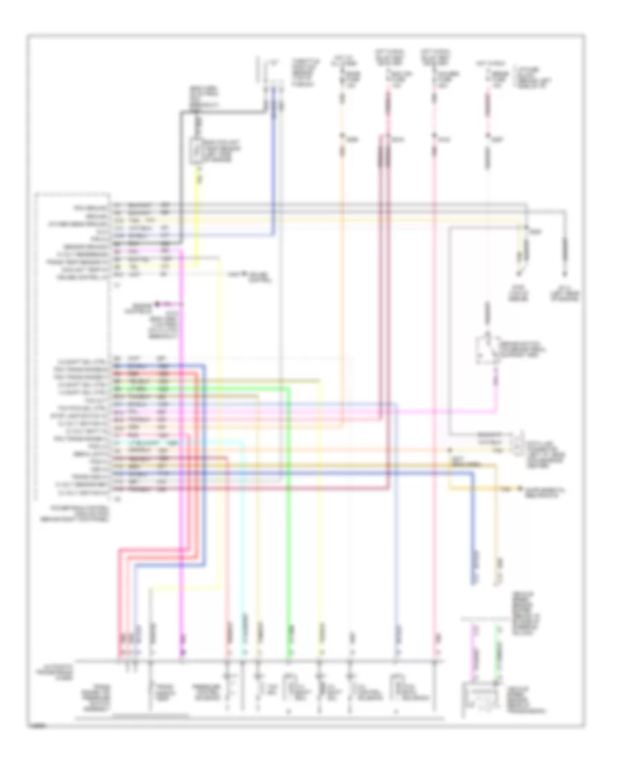
TRANSMISSION
4.3L
4.3L (VIN W), Transmission Wiring Diagram for Chevrolet Astro 1995
List of elements for 4.3L (VIN W), Transmission Wiring Diagram for Chevrolet Astro 1995:
- (eng harn, 35 cm from pcm breakout) s223
- 1-2 shift sol
- 1-2 shift sol ctrl
- 12 volt batt in
- 12 volt ignition in
- 2-3 shift sol
- 2-3 shift sol ctrl
- 3-2 control solenoid
- 3-2 shift sol ctrl
- 5 volt reference
- 5 volt sensor ref
- A12
- A14
- A15
- Automatic transmission (4l60e)
- B10
- Brake fuse 15a
- Brake switch (on brake pedal support arm)
- C11
- C12
- C13
- Coolant temp in
- Cruise control
- Cruise control in
- Data link connector (left i/p, near convenience center)
- Dlc
- E10
- E11
- E13
- E15
- E16
- Ecm ign fuse 10a
- Ecmb fuse 15a
- Eng coolant temp sensor (left side of engine)
- Engine controls
- F10
- F12
- F13
- F14
- F15
- G114 (left rear of engine)
- G125 (top of engine)
- Gauges fuse 20a
- Ground
- Hot at all times
- Hot in run
- Hot in run, bulb test or start
- I/p fuse block (behind left side of i/p)
- Oxygen sens ground
- Pcm ground
- Pcm trans range a
- Pcm trans range b
- Pcm trans range c
- Pcs hi
- Pcs lo
- Pnk
- Powertrain control module (pcm) (behind right kick panel)
- Pressure control solenoid
- Red
- S100
- S178 (eng harn, 4 cm from a/c clutch breakout)
- S216
- S220
- S277 (eng harn)
- S297
- S299
- Sensor ground
- Serial data
- Stop lamp switch in
- Tan
- Tcc out
- Tcc pwm sol ctrl
- Tcc pwm solenoid
- Tcc sol
- Throttle position sensor (top of plenum)
- Tps in
- Trans oss hi
- Trans range (tr) pressure switch assembly
- Trans temp sensor in
- Trans- mission temp
- Vehicle speed sensor (rear of transmission)
- Vehicle speed sensor buffer (behind i/p, rh side of steering column)
- Vss in
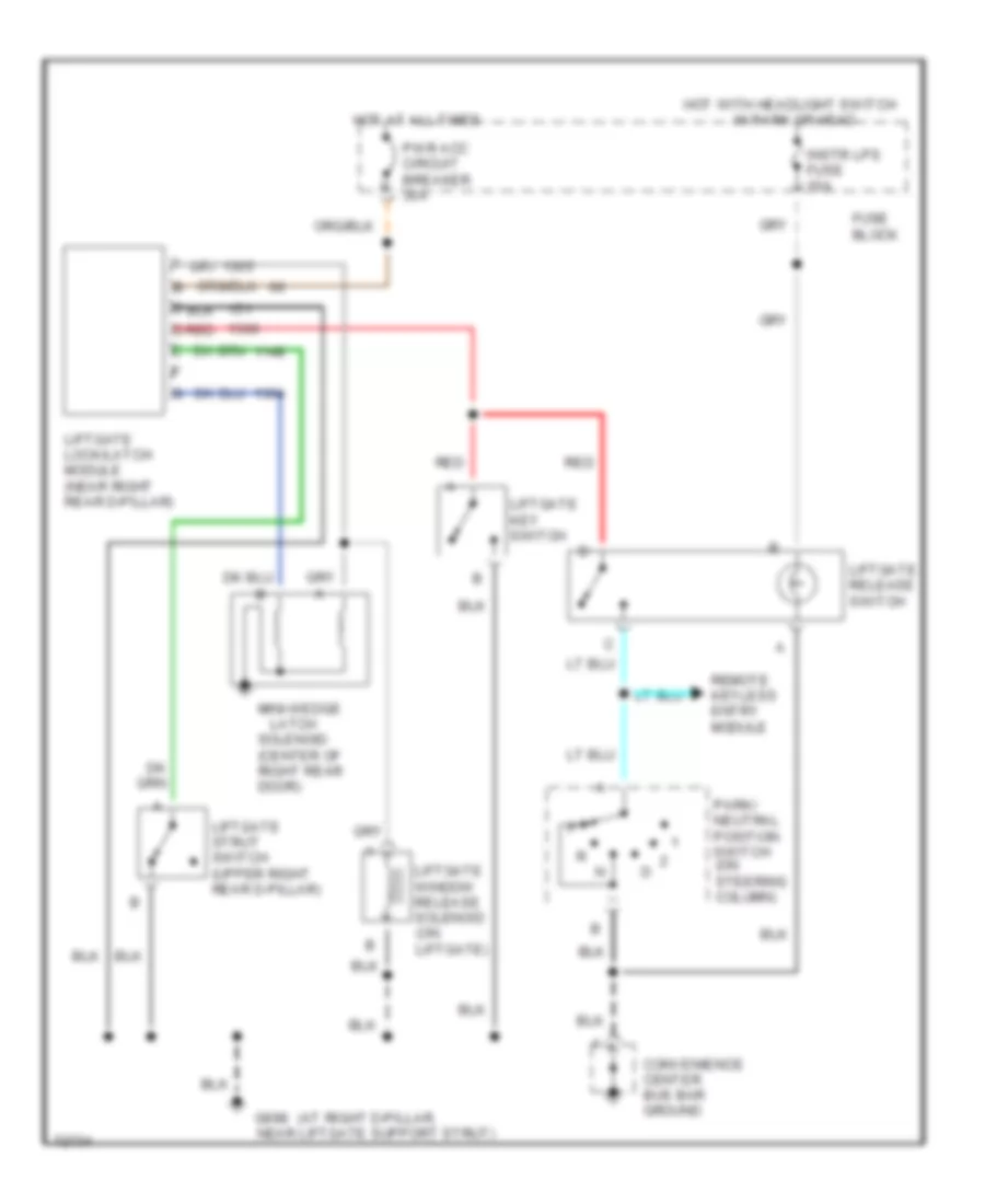
TRUNK, TAILGATE, FUEL DOOR
Rear Glass Release Wiring Diagram for Chevrolet Astro 1995
List of elements for Rear Glass Release Wiring Diagram for Chevrolet Astro 1995:
- (at right d-pillar,
- Convenience center bus bar ground
- Fuse block
- G998 near liftgate support strut)
- Hot at all times
- Hot with headlight switch in park or head
- Instr lps fuse 10a
- Latch
- Liftgate key switch
- Liftgate lock/latch module (near right rear d-pillar)
- Liftgate release switch
- Liftgate strut switch (upper right rear d-pillar)
- Liftgate window release solenoid (on liftgate)
- Mini-wedge
- Park/ neutral position switch (on steering column)
- Pwr acc circuit breaker 30a
- Red
- Remote keyless entry module
- Solenoid (center of right rear door)
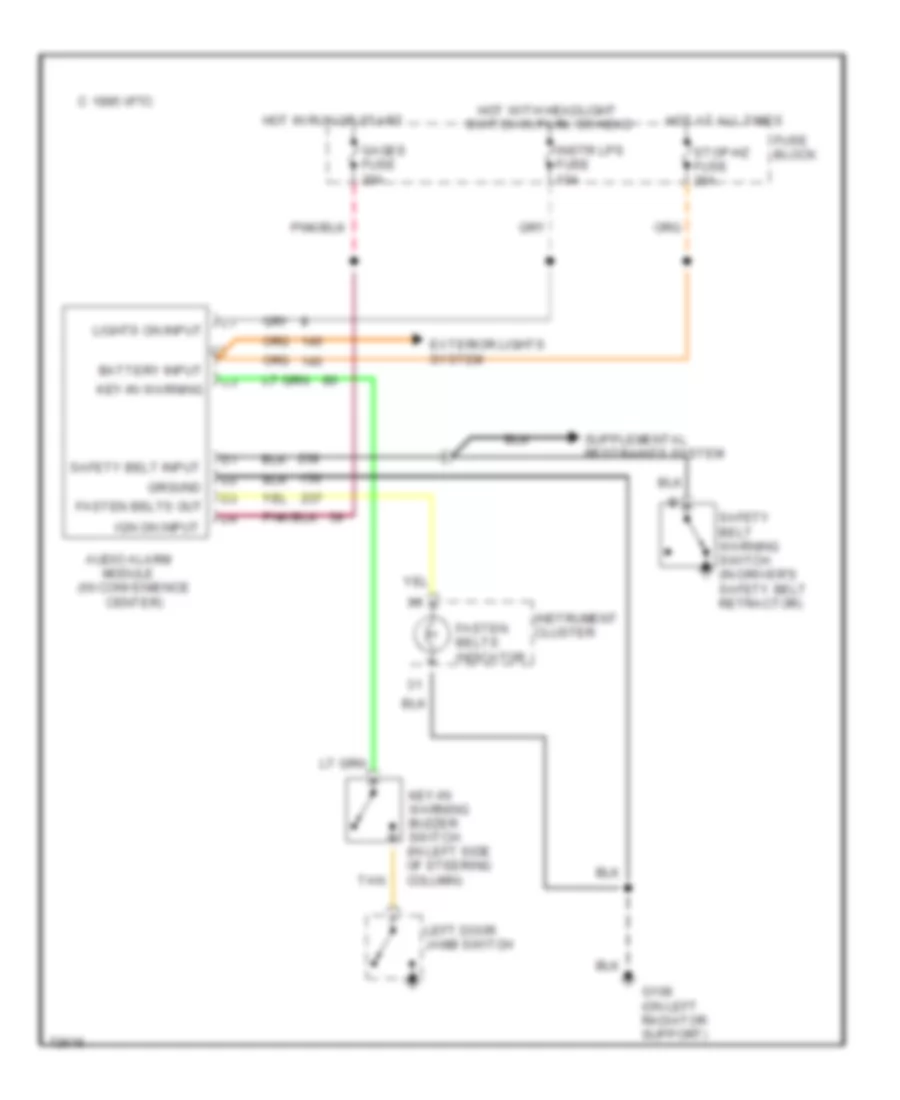
WARNING SYSTEMS
Warning System Wiring Diagrams for Chevrolet Astro 1995
List of elements for Warning System Wiring Diagrams for Chevrolet Astro 1995:
- Audio alarm module (in convenience center)
- Battery input
- C 1995 vftc
- Exterior lights system
- Fasten belts indicator
- Fasten belts out
- Fuse block
- G108 (on left radiator support)
- Gages fuse 20a
- Ground
- Hot at all times
- Hot in run or start
- Hot with headlight switch in park or head
- Ign on input
- Instr lps fuse 10a
- Instrument cluster
- Key-in warning
- Key-in warning buzzer switch (in left side of steering column)
- Left door jamb switch
- Lights on input
- Safety belt input
- Safety belt warning switch (in driver's safety belt retractor)
- Stop-hz fuse 20a
- Tan
WIPER/WASHER
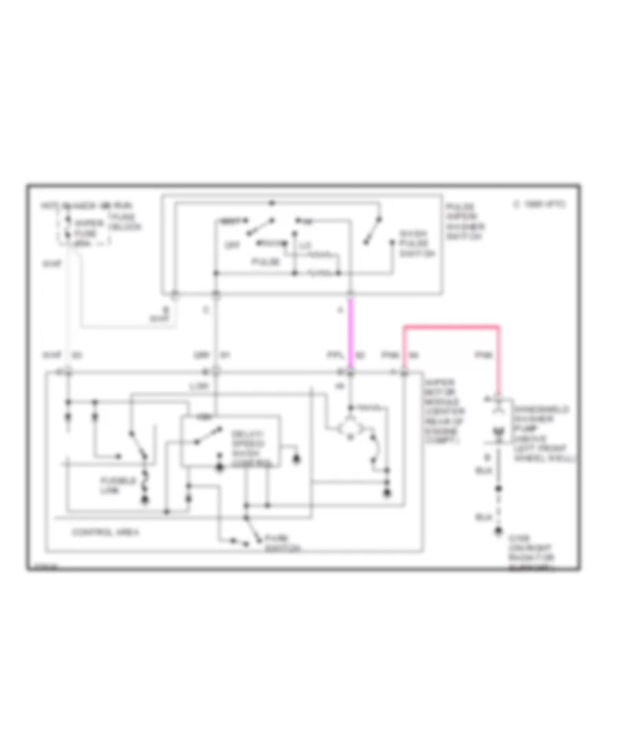
Front Wiper/Washer Wiring Diagram for Chevrolet Astro 1995
List of elements for Front Wiper/Washer Wiring Diagram for Chevrolet Astro 1995:
- C 1995 vftc
- Control area
- Delay/ speed/ wash control
- Fuse block
- Fusible link
- G109 (on right radiator support)
- Hot in accy or run
- Ign
- Low
- Mist
- Off
- Park switch
- Pnk
- Pulse
- Pulse wiper/ washer switch
- Wash pulse switch
- Windshield washer pump (above left front wheel well)
- Wiper fuse 25a
- Wiper motor module (center rear of engine compt)
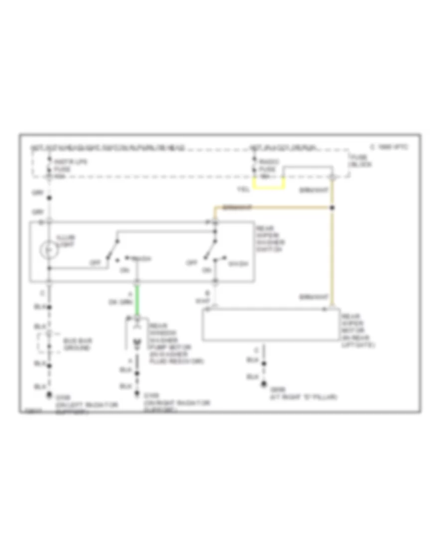
Rear Wiper/Washer Wiring Diagram for Chevrolet Astro 1995
List of elements for Rear Wiper/Washer Wiring Diagram for Chevrolet Astro 1995:
- Bus bar ground
- C 1995 vftc
- Fuse block
- G108 (on left radiator support)
- G109 (on right radiator support)
- G998 (at right "d" pillar)
- Hot in accy or run
- Hot with headlight switch in park or head
- Illum light
- Instr lps fuse 10a
- Off
- Radio fuse 15a
- Rear window washer pump motor (in washer fluid resovoir)
- Rear wiper motor (in rear liftgate)
- Rear wiper/ washer switch
- Wash

 Čeština
 Dansk
Dansk Deutsch
 Ελληνικά
 English
 English
 Suomi
Suomi Français
 Français
 עברית
עברית Hrvatski
 Magyar
 Italiano
 日本語
日本語 한국어
한국어 Nederlands
 Polski
 Português
 Português
 Română
 Русский
 Slovenčina
 Slovenščina
 Svenska
 Türkçe
 中文 (中国)