AIR CONDITIONING
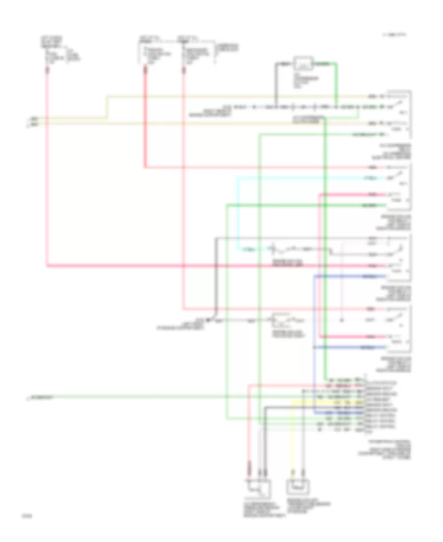
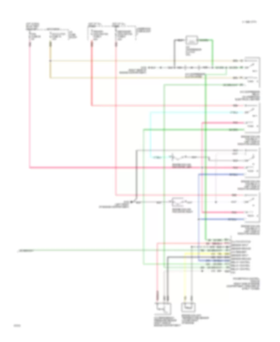
A/C Wiring Diagram, Auto A/C (1 of 2) for Chevrolet Corvette ZR-1 1995
 https://portal-diagnostov.com/license.html
Automotive Electricians Portal FZCO
Automotive Electricians Portal FZCO
https://portal-diagnostov.com/license.html
https://portal-diagnostov.com/license.html
Automotive Electricians Portal FZCO
Automotive Electricians Portal FZCO
List of elements for A/C Wiring Diagram, Auto A/C (1 of 2) for Chevrolet Corvette ZR-1 1995:
- (top center of i/p)
- +5 v ref
- +8 v ref
- +8 volt ref
- A/c blower fuse 4 30a
- A/c clutch fuse 18 10a
- A/c mdl fuse 1 5a
- A/c pressure cycling switch (right rear of engine compartment in a/c low pressure pipe)
- A/c prog fuse 43 5a
- A/c request out
- Air mix valve motor
- Battery
- Blower feedback
- Blower motor
- Blower motor control module (right rear of engine compartment)
- Blower speed ctrl
- C 1995 vftc
- C10
- C11
- C12
- C13
- C14
- C15
- C16
- Computer data lines system
- Control button led
- D10
- D11
- D12
- D13
- D14
- D15
- D16
- Data line
- G105 (right rear of engine compartment)
- G200 (behind left i/p on kick panel)
- Ground
- Hot at all times
- Hot in run
- Hvac control head
- Hvac programmer (below left side of i/p, right of steering column)
- I/p fuse block
- Ignition fused feed
- Ignition input
- Illumination
- Inside air temperature sensor (behind right side of i/p)
- Inside temp sensor
- Interior lights system
- Lcd display feed
- Mix valve feedbk
- Nca
- Outside temp sensor
- Outside temperature sensor (in right radiator shroud)
- Rear defog on
- Rear defog req
- Rear defogger system
- Red
- Sensor ground
- Serial data
- Solar sensor
- Sun load sensor
- Tan
- Temperature door motor (behind right side of i/p, on bottom heater case)
- Underhood fuse block 1
A/C Wiring Diagram, Auto A/C (2 of 2) for Chevrolet Corvette ZR-1 1995
List of elements for A/C Wiring Diagram, Auto A/C (2 of 2) for Chevrolet Corvette ZR-1 1995:
- +5v
- A/c compressor clutch coil
- A/c compressor clutch diode
- A/c compressor relay (in underhood electrical center)
- A/c refrigerant pressure sensor (right side of engine compartment)
- A/c request
- A10
- A11
- B16
- B21
- B29
- C 1995 vftc
- C25
- Clutch status
- D12
- Engine coolant temperature sensor (lower front of engine)
- Engine cooling fan motor, left
- Engine cooling fan motor, right
- Engine cooling fan relay 1 (left side of radiator shroud)
- Engine cooling fan relay 2 (left side of radiator shroud)
- Engine cooling fan relay 3 (left side of radiator shroud)
- Fan fuse 29 5a
- G100 (left front of engine compartment)
- G105 (right rear of engine compartment)
- Hot at all times
- Hot in run, bulb test,
- I/p fuse block
- Nca
- Or start
- Pnk
- Powertrain control module (right side of engine compartment, forward of strut tower)
- Primary cooling fan fuse 2 30a
- Red
- Relay control
- Secondary cooling fan fuse 5 40a
- Sensor ground
- Sensor input
- Underhood fuse block
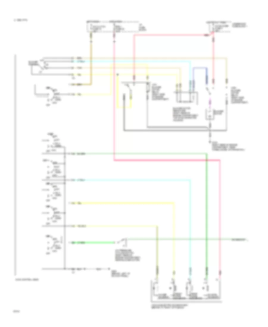
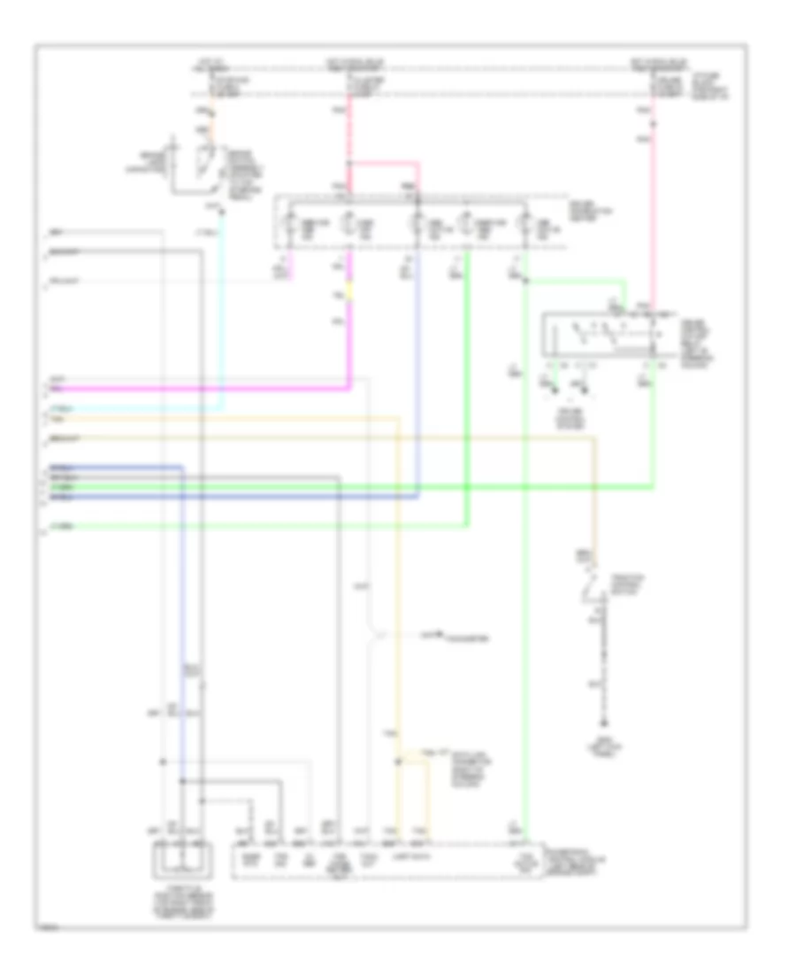
A/C Wiring Diagram, Manual A/C (1 of 2) for Chevrolet Corvette ZR-1 1995
List of elements for A/C Wiring Diagram, Manual A/C (1 of 2) for Chevrolet Corvette ZR-1 1995:
- A/c blower fuse 4 30a
- A/c clutch fuse 18 10a
- A/c pressure cycling switch (right rear of engine compartment, near blower motor)
- A/c-def solenoid
- B-lv norm
- Bi-level solenoid
- Blower motor
- Blower motor resistors (right rear of engine compartment, top of evaporator housing)
- Blower switch
- C 1995 vftc
- Def
- Eng 1 fuse 30 10a
- Front mode solenoid
- G105 (right rear of engine compartment, near wheelhouse, on frame rail)
- G200 (behind left i/p on kick panel)
- High blower motor relay (right side of engine compartment)
- Hot at all times
- Hot in run
- Htr
- Hvac control head
- I/p fuse block
- Low blower motor relay (right side of engine compartment)
- Max
- Off
- Pnk
- Rear mode solenoid
- Red
- Tan
- Underhood fuse block 1
- Vacuum/electric solenoid box (behind i/p, right of plenum)
- Vnt
A/C Wiring Diagram, Manual A/C (2 of 2) for Chevrolet Corvette ZR-1 1995
List of elements for A/C Wiring Diagram, Manual A/C (2 of 2) for Chevrolet Corvette ZR-1 1995:
- +5v
- A/c clutch fuse 18 10a
- A/c compressor clutch coil
- A/c compressor clutch diode
- A/c compressor relay (in underhood electrical center)
- A/c refrigerant pressure sensor (right side of engine compartment)
- A/c request
- A10
- A11
- B16
- B21
- B29
- C 1995 vftc
- C25
- Clutch status
- D12
- Engine coolant temperature sensor (lower front of engine)
- Engine cooling fan motor, left
- Engine cooling fan motor, right
- Engine cooling fan relay 1 (left side of radiator shroud)
- Engine cooling fan relay 2 (left side of radiator shroud)
- Engine cooling fan relay 3 (left side of radiator shroud)
- Fan fuse 29 5a
- G100 (left front of engine compartment)
- G105 (right rear of engine compartment)
- Hot at all times
- Hot in run
- Hot in run, bulb test,
- I/p fuse block
- Nca
- Or start
- Pnk
- Powertrain control module (right side of engine compartment, forward of strut tower)
- Primary cooling fan fuse 2 30a
- Red
- Relay control
- Secondary cooling fan fuse 5 40a
- Sensor ground
- Sensor input
- Underhood fuse block
ANTI-LOCK BRAKES
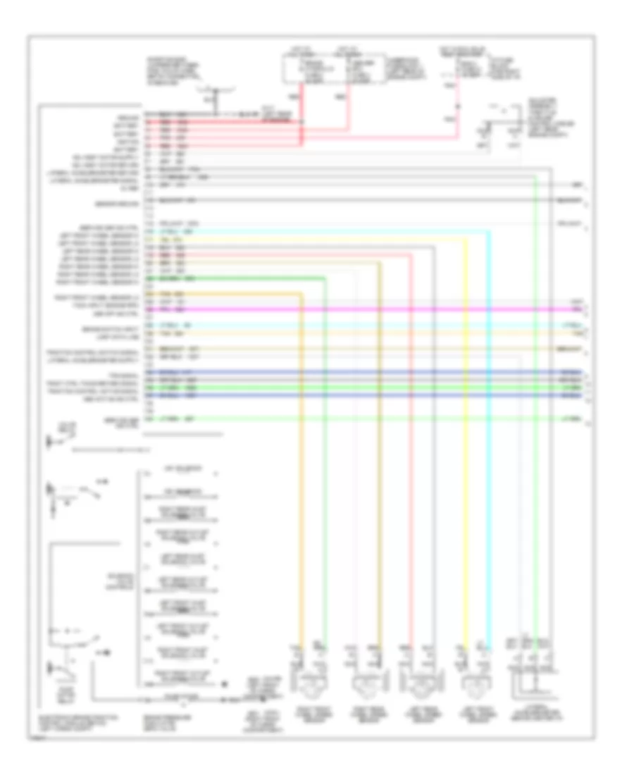
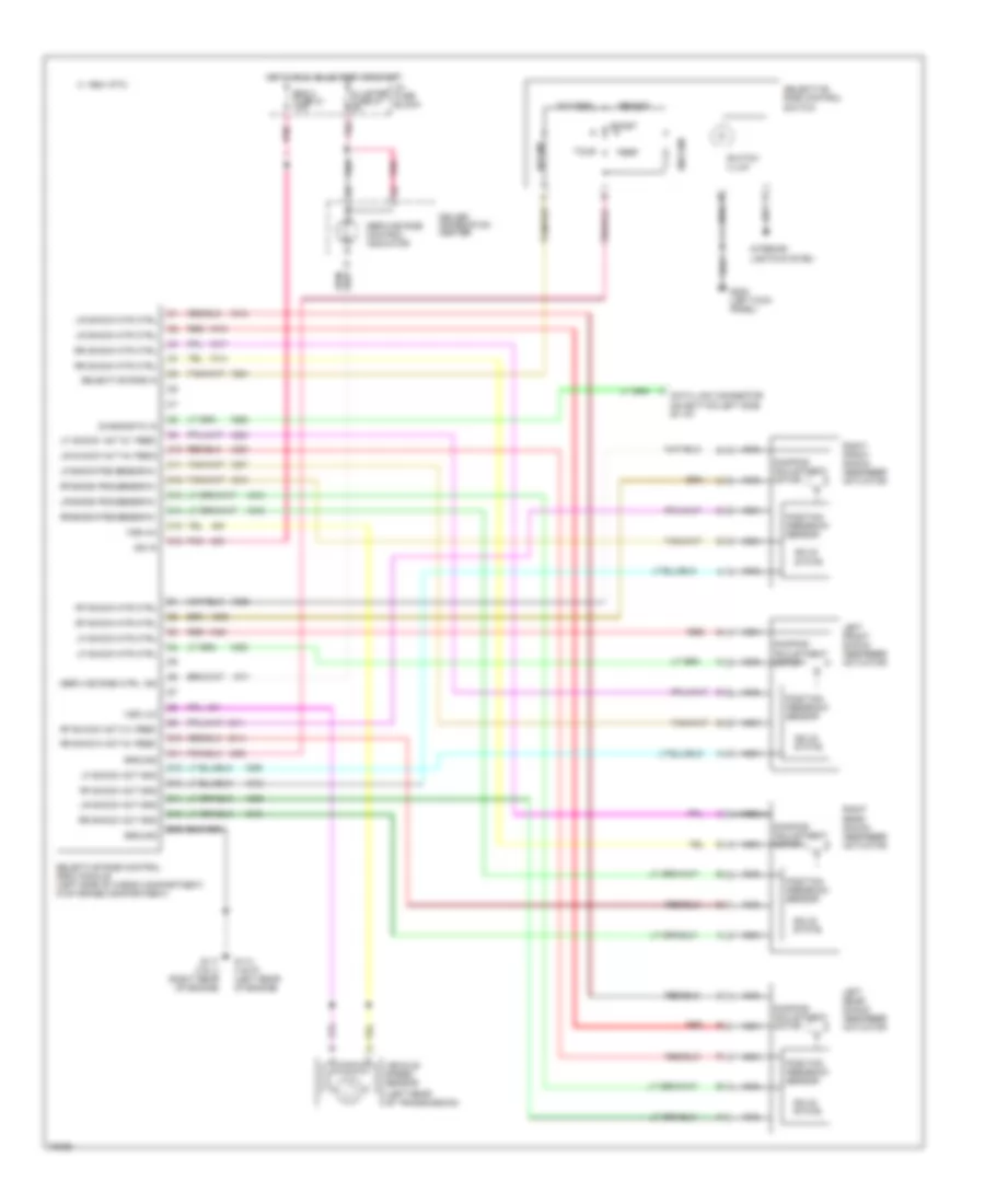
Anti-lock Brake Wiring Diagrams (1 of 2) for Chevrolet Corvette ZR-1 1995
List of elements for Anti-lock Brake Wiring Diagrams (1 of 2) for Chevrolet Corvette ZR-1 1995:
- (left front of cargo compartment)
- (right front of cargo compartment)
- -conv.
- -coupe
- 5v ref
- Abs active ind ctrl
- Abs/asr ecu fuse 3 20 amp
- Adj assy motor return
- Adjuster assembly- throttle & cruise control cables (left rear engine compt)
- Asr off ind ctrl
- Asv solenoid
- Bat
- Battery
- Brake hydraulic fuse 8 40 amp
- Brake pressure modulator (bpm) valve
- Brake switch input
- Electronic brake/traction control module (ebtcm) (left cargo compt)
- Eng 2 fuse 21 10 amp
- G117 (left rear of engine)
- G400
- G401
- Ground
- Hot at all times
- Hot in run, bulb test or start
- I/p fuse block (far right side of i/p)
- Ign
- Ignition
- Lateral accelerometer (behind center i/p)
- Lateral accelerometer return
- Lateral accelerometer signal
- Left front inlet solenoid valve
- Left front outlet solenoid valve
- Left front wheel sensor hi
- Left front wheel sensor lo
- Left front wheel speed sensor
- Left rear inlet solenoid valve
- Left rear outlet solenoid valve
- Left rear wheel sensor hi
- Left rear wheel sensor lo
- Left rear wheel speed sensor
- Nca
- Pnk
- Pump motor
- Pump motor relay
- Red
- Right front inlet solenoid valve
- Right front outlet solenoid valve
- Right front wheel sensor hi
- Right front wheel sensor lo
- Right front wheel speed sensor
- Right rear inlet solenoid valve
- Right rear outlet solenoid valve
- Right rear wheel sensor hi
- Right rear wheel sensor lo
- Right rear wheel speed sensor
- Sensor ground
- Service abs ind ctrl
- Service asr ind ctrl
- Shorting bar- jumpers between pins 15 & 40 when ebtcm connector is removed
- Solenoid valve controls
- Tach input (engine rpm)
- Tan
- Tps signal
- Tract ctrl timing retard signal
- Traction control active signal
- Traction control switch signal
- Uart data line
- Underhood fuse block 1 (left rear of engine compt)
- Usv solenoid
- Valve relay
Anti-lock Brake Wiring Diagrams (2 of 2) for Chevrolet Corvette ZR-1 1995
List of elements for Anti-lock Brake Wiring Diagrams (2 of 2) for Chevrolet Corvette ZR-1 1995:
- (left rear of engine compt)
- 5v ref
- A13
- Abs active ind.
- Asr active ind.
- Asr off ind.
- B28
- Brake lamp capacitor
- Brake switch assembly (mounted to top of brake pedal)
- C11
- C12
- C22
- Cluster fuse 27 5 amp
- Control module
- Cruise control cut-off relay (left of steering column)
- Cruise control system
- Cruise fuse 32 10 amp
- D29
- D30
- Data link connector (right of steering column)
- Driver information center
- G200 (left kick panel)
- Hot at all times
- Hot in run, bulb test or start
- I/p fuse block (far right side of i/p)
- Pnk
- Pnk pnk
- Powertrain
- Service abs ind.
- Service asr ind.
- Snsr rtn
- Stop-haz fuse 8 20 amp
- Tach out
- Tachometer
- Tan
- Tcs active sig
- Throttle position sensor (top right front of engine, side of throttle body)
- Tps sig
- Traction control switch
- Tsr timing retard out
- Uart data
ANTI-THEFT
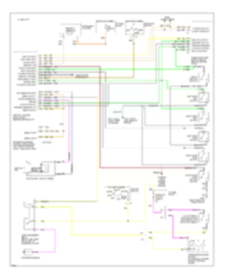
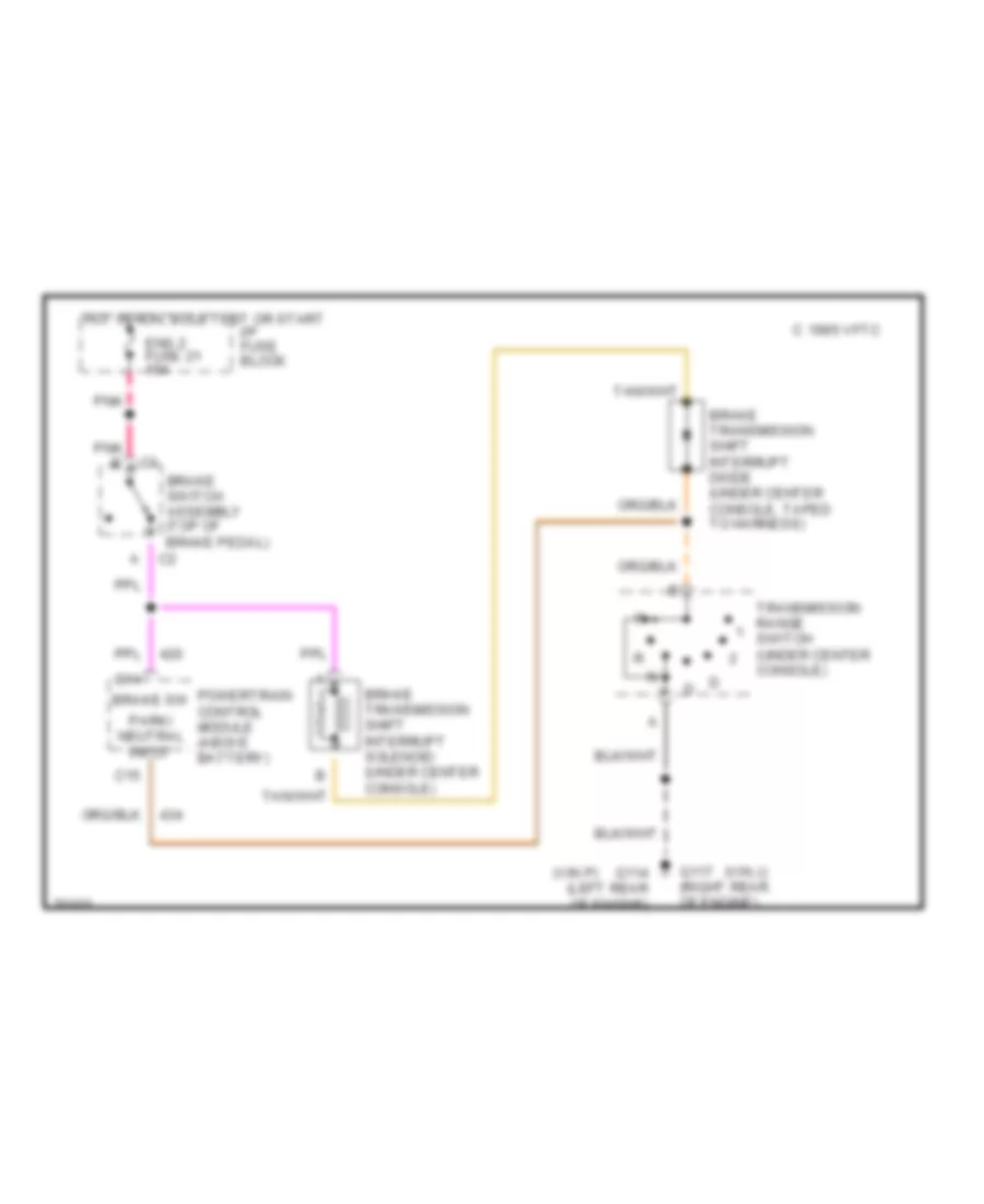
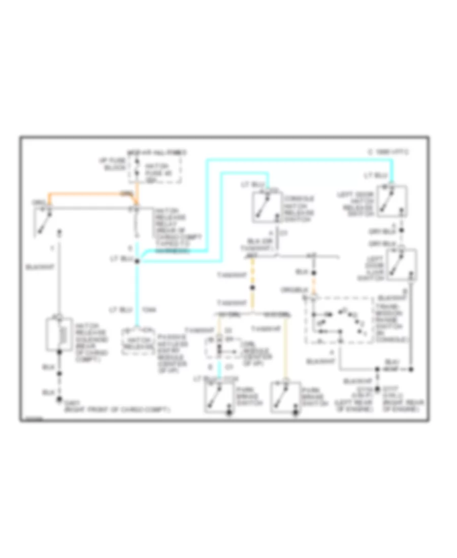
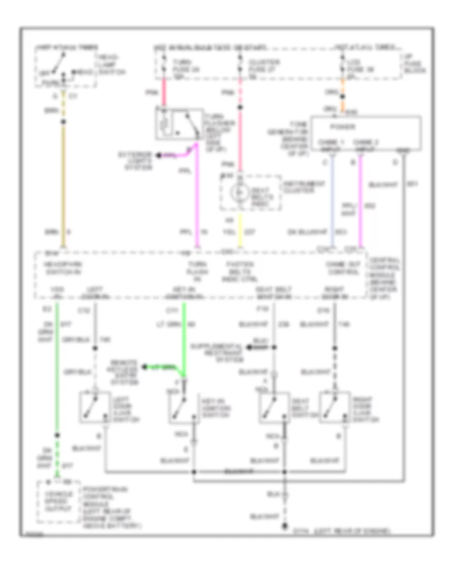
Anti-theft Wiring Diagram for Chevrolet Corvette ZR-1 1995
List of elements for Anti-theft Wiring Diagram for Chevrolet Corvette ZR-1 1995:
- (vin j)
- (vin p)
- 1995 vftc c
- A/t
- Accy
- Arm utd input
- Arm utd output
- B12
- B13
- Bulb test
- C10
- C11
- C12
- C16
- Central control module (ccm) (behind center of i/p)
- Clutch pedal
- Compt, above battery)
- Crank p/n clutch fuse 10 5a
- D14
- D15
- D16
- D29
- D30
- Disarm input
- Door key sw out
- Door locks system
- E12
- E13
- F12
- G114 (left rear of engine)
- G117 (right rear of engine)
- G401 (right front of cargo compt)
- Ground
- Hatch ajar input
- Hatch door ajar switch (coupe)
- Head
- Headlamp switch
- Horn rly control
- Horn system (horn relay)
- Hot at all times
- I/p fuse block
- Ignition key
- Ignition key lock cylinder
- Ignition switch
- Instrument cluster
- Interior lights system (diode module)
- Key in ign input
- Key resistor input
- Key-in ign input
- Key-in ignition switch
- Lcd fuse 38 5a
- Left door ajar switch
- Left door key switch
- Lk both door out
- Lock
- Lock (arm) input
- Lt door ajar input
- Lt door unlk out
- M/t
- Nca
- Off
- Park
- Park/headlt input
- Passive keyless entry module (behind center of i/p)
- Position switch (mounted to top of clutch pedal)
- Powertrain/engine control module (pcm) (left rear of engine
- Program request
- Program request out
- Resistor pellet
- Right door ajar switch
- Right door key switch
- Rt door ajar input
- Run
- Security ind
- Security indicator
- Serial data
- Serial data 1
- Serial data 2
- Start
- Start enable rly
- Starter solenoid
- Tan
- Theft deterrent relay (below left side of i/p, left of steering column)
- Transmission range switch (in console, at base of shift control lever)
- Unlock input
- Utd status input
- Utd status out
- Vin j
- Vin p
- Vin p only
BODY COMPUTER
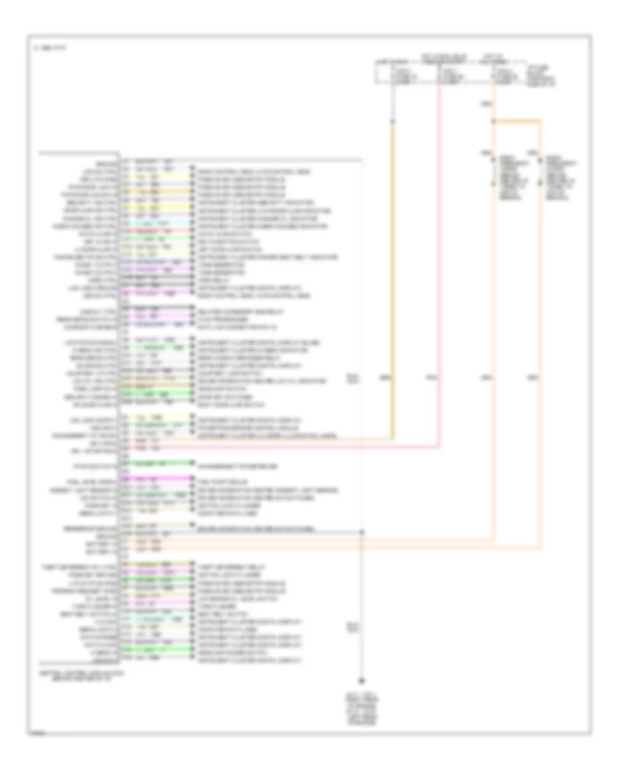
Central Control Module Wiring Diagram for Chevrolet Corvette ZR-1 1995
List of elements for Central Control Module Wiring Diagram for Chevrolet Corvette ZR-1 1995:
- (left rear of engine)
- (right rear of engine)
- -vin j
- -vin p
- 1995 vftc c
- C1 ground
- C10 hatch ajar in
- C11 key in ign in
- C12 lh door ajar in
- C13 fasten belts ind ctrl
- C14 chime 1 output
- C15 chime 2 output
- C16 horn ctrl
- C2 lcd dim ctrl
- C3 arm utd (pke)
- C4 pwr door lock in
- C5 pwr door unlock in
- C6 security ind ctrl
- C7 door ajar ind ctrl
- C8 change oil ind ctrl
- C9 check gauges ind ctrl
- Ccm 1 fuse 25 5 amp
- Ccm 2 fuse 39 5 amp
- Ccm 3 fuse 16 5 amp
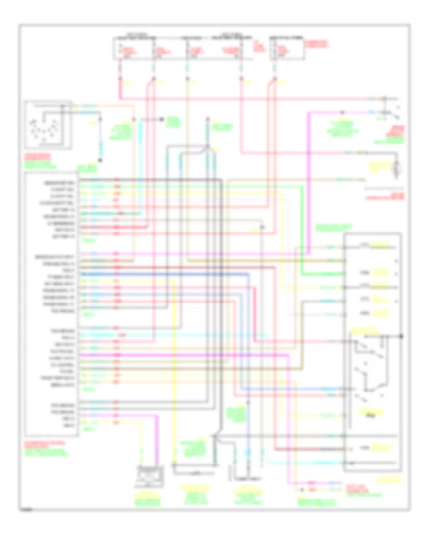
- Central control module (ccm) (behind center of i/p)
- Computer data lines
- Courtesy lamp switch
- D1 lcd logic ground
- D10 rear defog ctrl
- D11 blanking ctrl
- D12 courtesy lp ctrl
- D13 low oil ind ctrl
- D14 park lamp on in
- D15 security disarm in
- D16 rh door ajar in
- D2 led dim ctrl
- D4 dab rly ctrl
- D5 rear defog switch in
- D6 diagnostic enable
- D8 lcd pwm dim signal
- D9 hi beam ind ctrl
- Data link connector (pin 12)
- Delayed accessory bus relay
- Door key switches
- Driver information center (ambient light sensor)
- Driver information center (dic switches)
- Driver information center (low oil indicator)
- E10 ambient light sensor in
- E11 dic switch in
- E12 pass-key in
- E13 serial data 1
- E14
- E15 reference ground
- E16 ground
- E2 vss input
- E3 incandesent i/p lps dim
- E4 ign 3 (run)
- E5 ign 1 (start/run)
- E7 i/p dim switch in
- E9 fuel level signal
- F1 battery in
- F10 seat belt switch in
- F11 m clock
- F12 serial data 2
- F13 data strobe
- F14 data clock
- F15 hi beam in
- F16 lcd data
- F2 battery in
- F4 theft deterrent rly ctrl
- F5 pass-key return
- F6 utd status (pke)
- F7 program request (pke)
- F8 oil level in
- F9 turn flasher in
- Fuel pump module
- G114
- G117
- Hatch ajar switch
- Headlamp dimmer switch
- Headlamp switch
- Horn relay
- Hot at all times
- Hot in run
- Hot in run, bulb test or start
- Hvac programmer
- I/p fuse block (far right side of i/p)
- Ignition lock cylinder
- Incandescent power driver
- Instrument cluster (change oil indicator)
- Instrument cluster (check gauges indicator)
- Instrument cluster (cluster illumination lamps)
- Instrument cluster (digital display bulbs)
- Instrument cluster (digital display)
- Instrument cluster (fasten seat belt indicator)
- Instrument cluster (hi beam indicator)
- Instrument cluster (security indicator)
- Instrument cluster (vin p-door ajar indicator)
- Key-in-ignition switch
- Left door ajar switch
- Low engine oil level switch
- Passive keyless entry module
- Pnk
- Powertrain/engine control module
- Radio control head, hvac control head
- Radio frequency choke (behind center i/p, taped to ccm c2 branch)
- Rear window defogger relay
- Right door ajar switch
- Seat belt switch
- Tan
- Theft deterrent relay
- Tone generator
- Turn flasher
COMPUTER DATA LINES
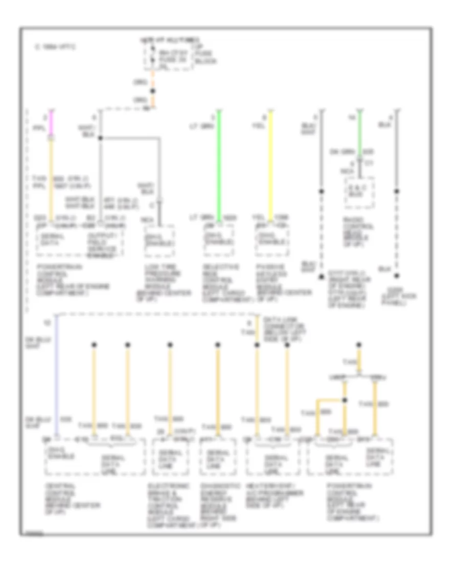
Data Link Connector Wiring Diagram for Chevrolet Corvette ZR-1 1995
List of elements for Data Link Connector Wiring Diagram for Chevrolet Corvette ZR-1 1995:
- (behind center of i/p)
- (left kick panel)
- (vin j)
- (vin j) (vin p)
- (vin p)
- (vin p) (vin j)
- 1994 vftc c
- A11
- B2 d20
- C10
- Central control module (behind center of i/p)
- D15
- D20 d7
- D29
- D30
- Data link connector (below left side of i/p)
- Diag. enable
- Diagnostic energy reserve module (behind right side of i/p)
- E & c bus
- E13
- Electronic brake & traction control module (left cargo compartment)
- F12
- G117 (right rear of engine) g114 (left rear of engine)
- G200
- Heater/vent/ a/c programmer (behind left side of i/p)
- Hot at all times
- I/p fuse block
- Low tire pressure warning module
- Nca
- Output/ field service enable
- Passive keyless entry module (behind center of i/p)
- Powertrain control module (left rear of engine compartment)
- Radio control head (middle of i/p)
- Rh ctsy fuse 36 5a
- Selective ride control module (left cargo compartment)
- Serial data
- Serial data line
- Tan
- Vin j
- Vin p
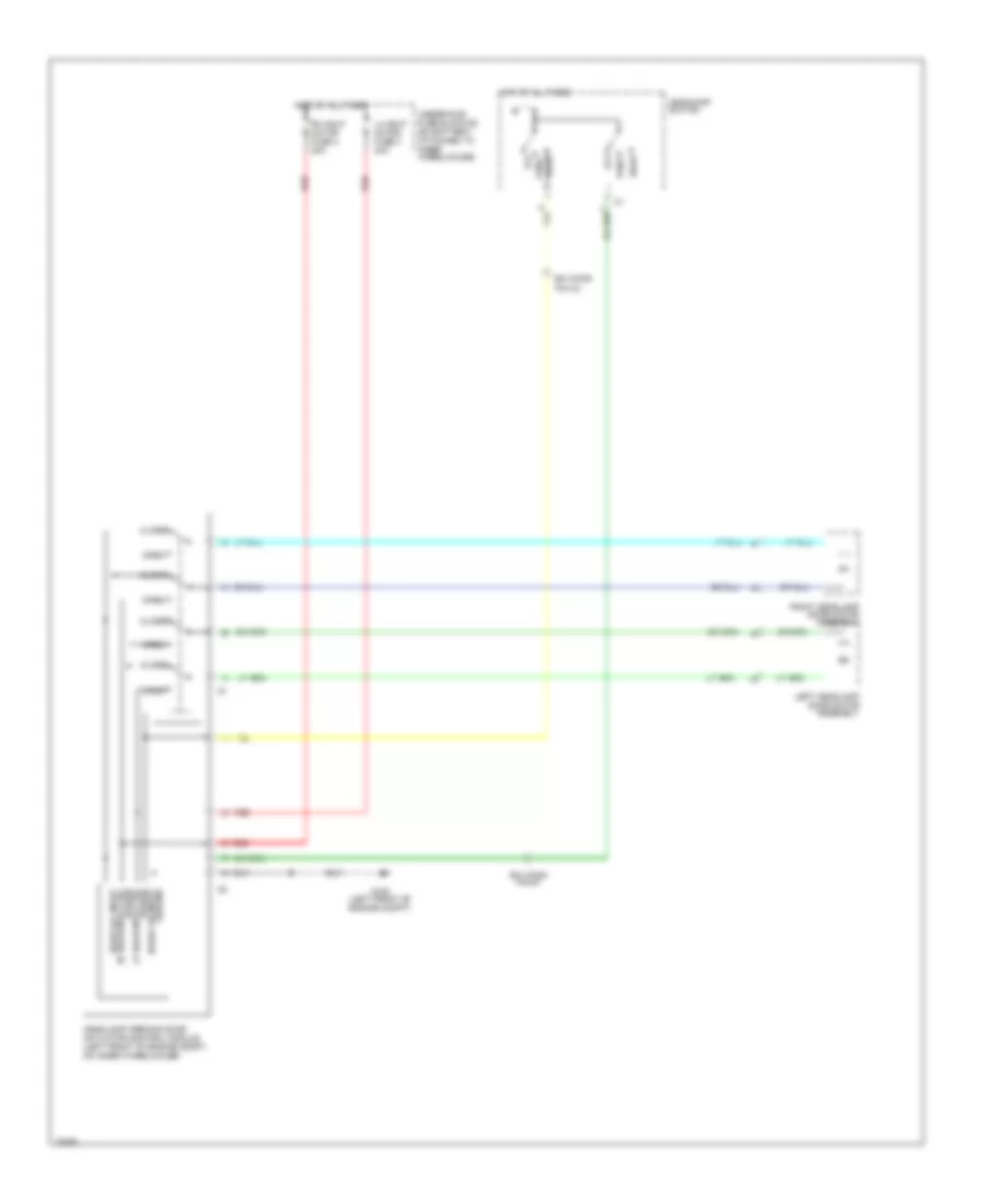
COOLING FAN
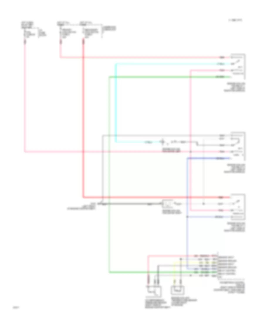
Cooling Fan Wiring Diagram for Chevrolet Corvette ZR-1 1995
List of elements for Cooling Fan Wiring Diagram for Chevrolet Corvette ZR-1 1995:
- +5v
- A/c refrigerant pressure sensor (right side of engine compartment)
- A10
- A11
- B16
- B29
- C 1995 vftc
- C25
- D12
- Engine coolant temperature sensor (lower front of engine)
- Engine cooling fan motor, left
- Engine cooling fan motor, right
- Engine cooling fan relay 1 (left side of radiator shroud)
- Engine cooling fan relay 2 (left side of radiator shroud)
- Engine cooling fan relay 3 (left side of radiator shroud)
- Fan fuse 29 5a
- G100 (left front of engine compartment)
- Hot at all times
- Hot in run, bulb test,
- I/p fuse block
- Or start
- Pnk
- Powertrain control module (right side of engine compartment, forward of strut tower)
- Primary cooling fan fuse 2 30a
- Red
- Relay control
- Secondary cooling fan fuse 5 40a
- Sensor ground
- Sensor input
- Underhood fuse block
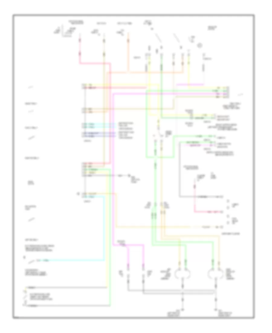
CRUISE CONTROL
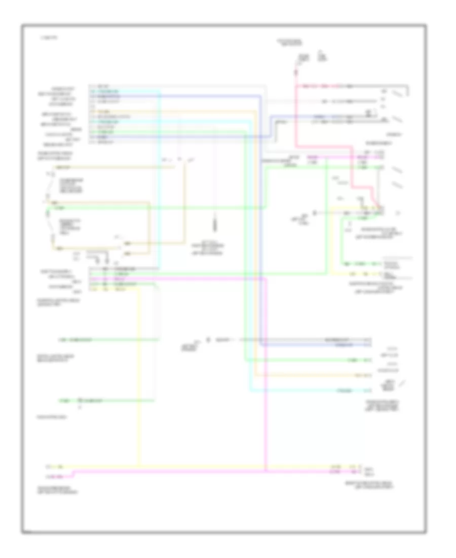
Cruise Control Wiring Diagram for Chevrolet Corvette ZR-1 1995
List of elements for Cruise Control Wiring Diagram for Chevrolet Corvette ZR-1 1995:
- (left cargo compartment)
- (above battery)
- (asr ind)
- (behind center of i/p)
- (left kick
- (left of i/p fuse block)
- (left of steering column)
- (left rear
- (left rear of engine
- (left rear of engine)
- (left rear of transmission)
- (right rear of engine)
- (top of brake
- (top of clutch
- 1995 vftc c
- 4000 pulses/mile
- A/t
- A11
- A17
- A31
- A32
- Active sig
- Asr active signal
- Assembly
- B22
- Block
- Brake switch
- C11
- C15
- Central control module
- Clutch sw
- Compt, above battery)
- Control
- Control module
- Cruise
- Cruise control cut off
- Cruise control module
- Cruise control servo
- Cruise engage sw
- Cruise on input
- Cruise release
- Cruise sw
- Cut off relay
- Disengage input
- Driver
- Elec trans sched in
- Elec trans sched out
- Electronic brake & traction
- Fuse
- Fuse 32
- G114
- G114 (vin p)
- G117 (vin j)
- G200
- Ground
- Hot in run, bulb
- I/p
- Information center
- M/t
- Nca
- Of engine)
- Off
- Panel)
- Pedal bracket)
- Pedal)
- Pnk
- Position
- Powertrain control module
- R/a
- Radio control head
- Relay
- Resume/accel input
- Selective ride control module
- Sensor
- Servo
- Servo position in/hi
- Servo position in/lo
- Set
- Set input
- Tan
- Tan 398
- Test or start
- Traction
- Vacuum valve
- Vacuum valve ctrl
- Vehicle speed sensor
- Vent valve
- Vent valve ctrl
- Vin j
- Vin p
- Vss hi
- Vss lo
DEFOGGERS
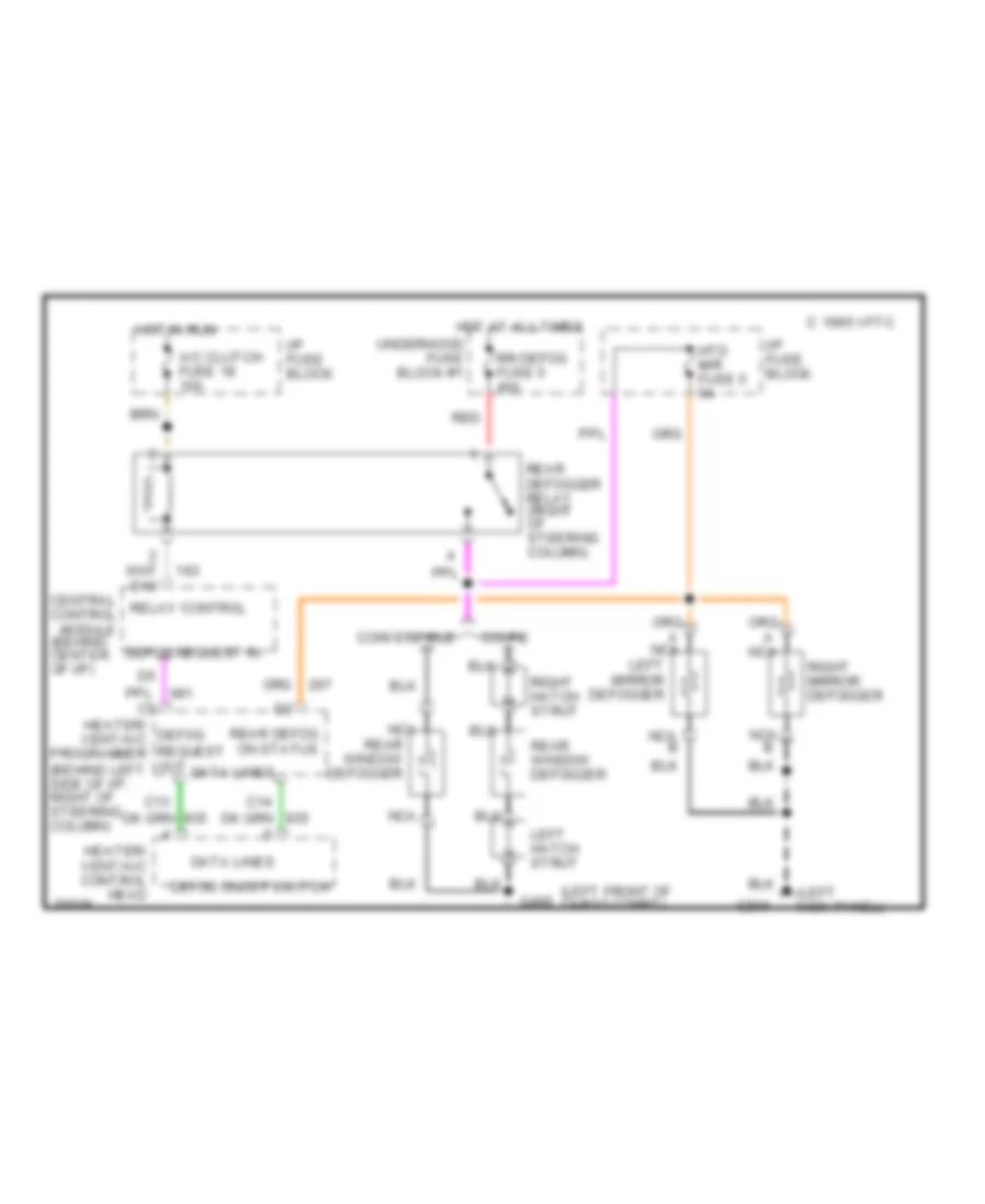
Defogger Wiring Diagram, with Electronic A/C for Chevrolet Corvette ZR-1 1995
List of elements for Defogger Wiring Diagram, with Electronic A/C for Chevrolet Corvette ZR-1 1995:
- (behind center of i/p)
- (behind left side of i/p, right of steering column)
- (left front of cargo compt)
- (left kick panel)
- 1995 vftc c
- A/c clutch fuse 18 10a
- C13
- Central relay control control module
- Convertible
- Coupe
- D10
- Data lines
- Defog on/off switch
- Defog request in
- G200
- G400
- Heater/ defog vent/a/c request programmer
- Heater/ vent/a/c control head
- Hot at all times
- Hot in run
- Htd mir fuse 5 5a
- I/p fuse block
- Left hatch strut
- Left mirror defogger
- Nca
- Nca b
- Out
- Rear defog on status
- Rear defogger relay (right of steering column)
- Rear window defogger
- Red
- Right hatch strut
- Right mirror defogger
- Rr defog fuse 5 40a
- Underhood fuse block #1
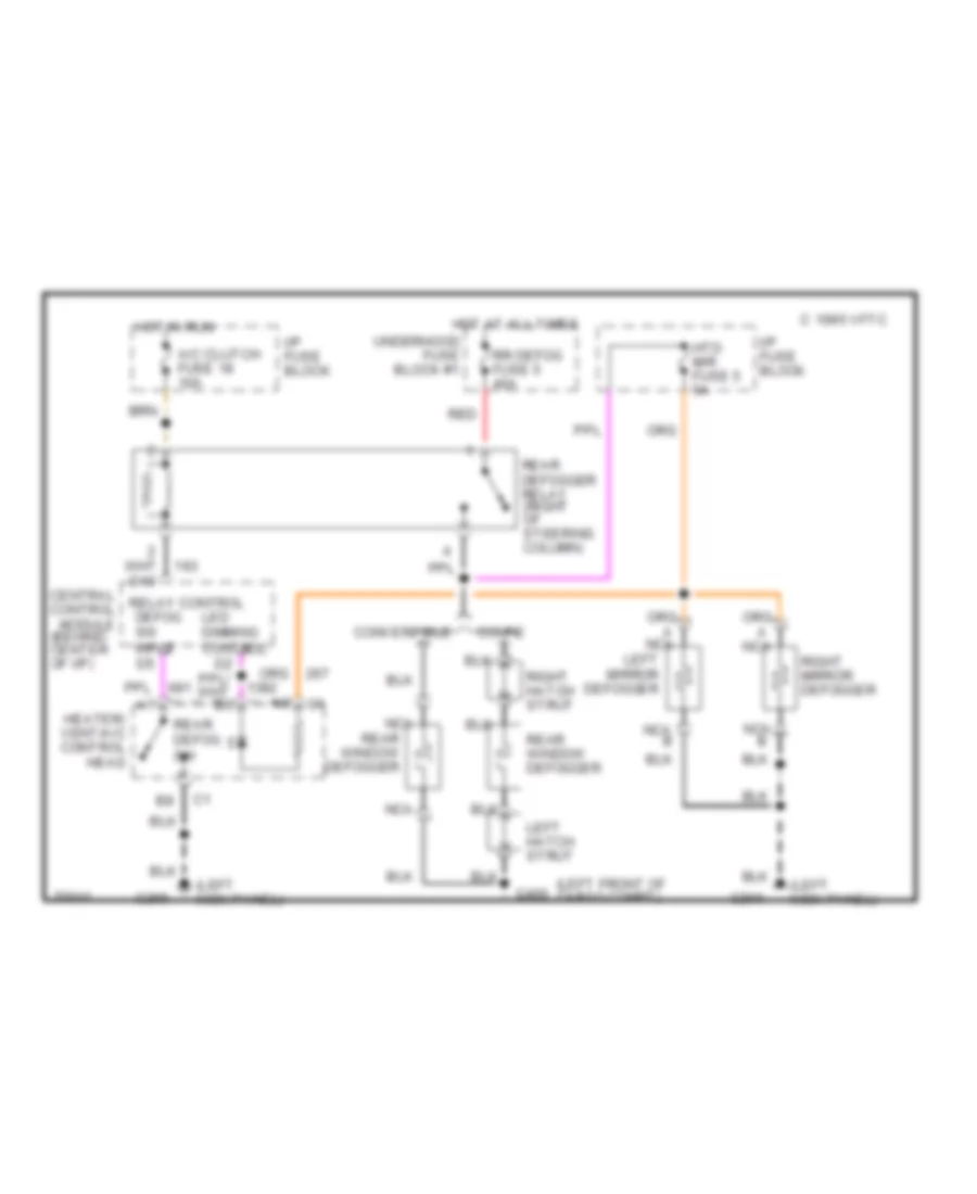
Defogger Wiring Diagram, with Manual A/C for Chevrolet Corvette ZR-1 1995
List of elements for Defogger Wiring Diagram, with Manual A/C for Chevrolet Corvette ZR-1 1995:
- (behind center of i/p)
- (left front of cargo compt)
- (left kick panel)
- 1995 vftc c
- A/c clutch fuse 18 10a
- Central relay control control module
- Convertible
- Coupe
- D10
- Defog sw input
- G200
- G400
- Heater/ vent/a/c control head
- Hot at all times
- Hot in run
- Htd mir fuse 5 5a
- I/p fuse block
- Led dimming control
- Left hatch strut
- Left mirror defogger
- Nca
- Nca b
- Rear defog sw
- Rear defogger relay (right of steering column)
- Rear window defogger
- Red
- Right hatch strut
- Right mirror defogger
- Rr defog fuse 5 40a
- Underhood fuse block #1
ELECTRONIC SUSPENSION
Electronic Suspension Wiring Diagram for Chevrolet Corvette ZR-1 1995
List of elements for Electronic Suspension Wiring Diagram for Chevrolet Corvette ZR-1 1995:
- (left rear of transmission)
- (on bottom left side of i/p)
- 165 ohm
- 1994 vftc c
- 50 ohm
- 500 ohm
- 84.5 ohm
- C10
- C11
- C12
- C13
- C14
- C15
- C16
- Cluster fuse 27 5a
- D10
- D11
- D12
- D13
- D14
- D15
- D16
- Damping adjustment motor
- Data link connector
- Diagnostic in
- Driver information center
- Eng 2 fuse 21 10a
- G114 (vin p) (left rear of engine)
- G117 (vin j) (right rear of engine)
- G200 (left kick panel)
- Ground
- Hot in run, bulb test or start
- I/p fuse block
- Ign in
- Interior lights system
- Left front shock absorber actuator
- Left rear shock absorber actuator
- Lf shock act 5v feed
- Lf shock act gnd
- Lf shock mtr ctrl
- Lf shock pos sensor in
- Lr shock act 5v feed
- Lr shock act gnd
- Lr shock mtr ctrl
- Lr shock pos sensor in
- Nca
- Perf
- Pnk
- Position feedback sensor
- Red
- Rf shock act 5v feed
- Rf shock act gnd
- Rf shock mtr ctrl
- Rf shock pos sensor in
- Right front shock absorber actuator
- Right rear shock absorber actuator
- Rr shock act 5v feed
- Rr shock act gnd
- Rr shock mtr ctrl
- Rr shock pos sensor in
- Selective ride control (src) module (left side of cargo compartment, in storage compartment)
- Selective ride control switch
- Selective ride in
- Service ride control indicator
- Service ride ctrl ind
- Solid state
- Sport
- Switch illum
- Tour
- Vehicle speed sensor
- Vss (hi)
- Vss (lo)
ENGINE PERFORMANCE
5.7L
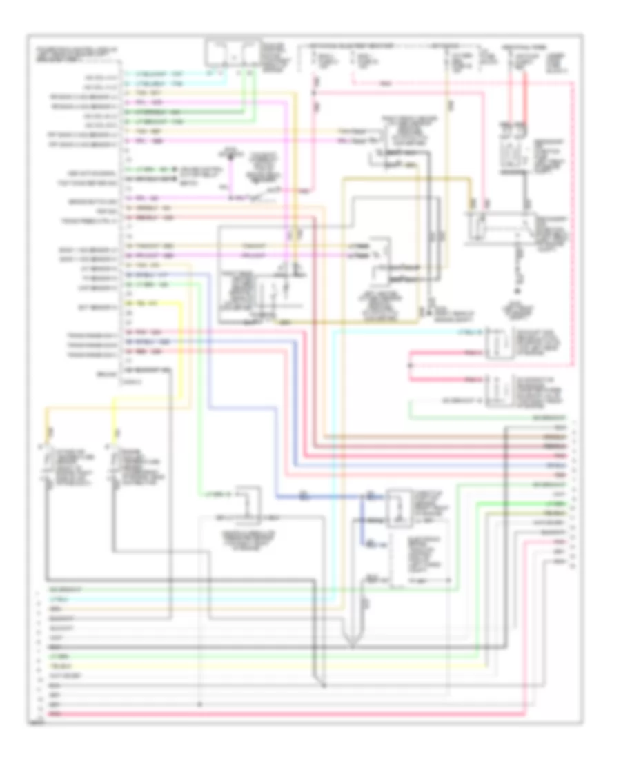
5.7L (VIN P), Engine Performance Wiring Diagrams (1 of 3) for Chevrolet Corvette ZR-1 1995
List of elements for 5.7L (VIN P), Engine Performance Wiring Diagrams (1 of 3) for Chevrolet Corvette ZR-1 1995:
- (below throttle body)
- (left rear of engine)
- (m/t) 2&3 block ctrl
- 324 (m/t)
- 5 volt ref
- 687 (a/t)
- A/c clutch status
- A/c request sig
- Air conditioning
- Air conditioning compressor
- Air pump relay ctrl
- Battery
- Coil wire
- Conn a
- Conn b
- Control module (m/t)
- Coolant fan relays
- Cruise active signal
- Cruise control module
- Cruise control, speedo, radio, cent ctrl module
- Dist ignition feed
- Dist ref low sig
- Distributor
- E.c.m. fuse 33 5a
- Egr solenoid ctrl
- Eng 1 fuse 30 10a
- Fuel injector #1
- Fuel injector #2
- Fuel injector #3
- Fuel injector #4
- Fuel injector #5
- Fuel injector #6
- Fuel injector #7
- Fuel injector #8
- Fuel pump relay ctrl
- G114
- G114 (left rear of engine)
- Ground
- Hi res signal
- High resolution sig
- Hot at all times
- Hot in run, bulb test or start
- I/p fuse block
- Ign voltage
- Ignition
- Ignition coil
- Ignition ctrl
- Inj # 8 ctrl
- Inj #1 ctrl
- Inj #2 ctrl
- Inj #3 ctrl
- Inj #4 ctrl
- Inj #5 ctrl
- Inj #6 ctrl
- Inj #7 ctrl
- Inj 1 fuse 22 10a
- Inj 2 fuse 23 10a
- Low res signal
- Low resolution sig
- Maf sensor in
- Mass air flow sensor (front of engine, in air intake duct)
- Optical sensor
- Pcm fuse 1 20a
- Pnk
- Pnk c
- Powertrain control module (left rear of engine cmpt, above battery)
- Pri cool fan relay ctrl
- Red
- Ref low
- Sec cool fan relay ctrl
- Selective ride
- Sensor ground
- Solid state
- Spark plugs
- Tach output
- Tachometer, electronic brake/ traction control module
- Trans 1-2 shift ctrl
- Trans 2-3 shift ctrl
- Trans 3-2 shift ctrl
- Under- hood fuse block 1
- Vehicle speed sensor (left rear of transmission)
- Vss ground
- Vss out
- Vss signal
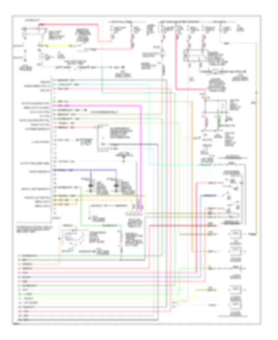
5.7L (VIN P), Engine Performance Wiring Diagrams (2 of 3) for Chevrolet Corvette ZR-1 1995
List of elements for 5.7L (VIN P), Engine Performance Wiring Diagrams (2 of 3) for Chevrolet Corvette ZR-1 1995:
- (left front of engine compt)
- Air pump fuse 8 20a
- Asr active signal
- Bank 1 h02 sensor lo
- Bank 1 ho2 sensor hi
- Brake switch sig
- Btsi solenoid
- Conn c
- Cruise control cut-off relay
- Ebtcm
- Ect sensor in
- Electronic brake/ traction control module (left cargo compt)
- Eng 1 fuse 30 10a
- Eng 2 fuse 21 10a
- Engine coolant temperature sensor (lower front of engine, near distributor)
- Evaporative emissions canister purge solenoid valve (top right front of engine)
- Exhaust gas recirculation solenoid valve (top left rear of engine)
- Frt bank 2 ho2 sensor hi
- Frt bank 2 ho2 sensor lo
- G100
- G105 (right rear of engine compt)
- Ground
- Hot at all times
- Hot in run
- Hot in run, bulb test or start
- I/p fuse block
- Iac coil a hi
- Iac coil a lo
- Iac coil b hi
- Iac coil b lo
- Iat sensor in
- Idle air control motor (top right front of engine)
- Intake air temperature sensor (front of engine, right side of air intake duct)
- Left heated oxygen sensor (bank #1, forward of catalytic converter)
- Manifold absolute pressure sensor (top right front
- Map sensor in
- Nca
- Of engine)
- Oxygen sen fuse 20 15a
- Pnk
- Pnp sig
- Powertrain control module (left rear of engine cmpt, above battery)
- Red
- Right front heated oxygen sensor (bank #2, forward of catalytic converter)
- Right rear heated oxygen sensor (bank #2, rear of catalytic converter)
- Rr bank 2 ho2 sensor hi
- Rr bank 2 ho2 sensor lo
- Secondary air injection pump (left front of engine compt)
- Secondary air injection pump relay (left front of engine compt)
- Solenoid
- Tan
- Tan b
- Tcc/shift interrupt switch (top of brake pedal bracket)
- Tcs timing retard sig
- Throttle position sensor (right front of engine)
- Tp sensor in
- Trans press ctrl hi
- Trans range sig a
- Trans range sig b
- Trans range sig c
- Under- hood fuse block 2
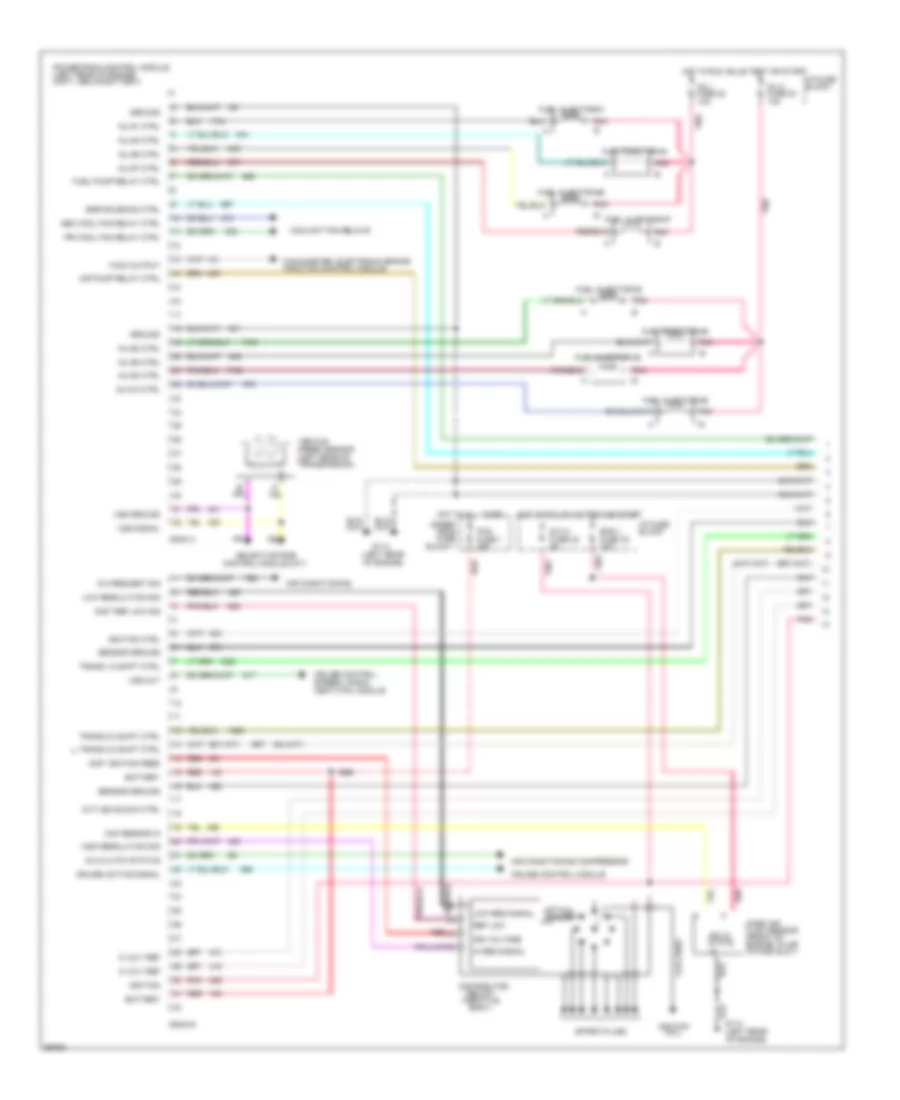
5.7L (VIN P), Engine Performance Wiring Diagrams (3 of 3) for Chevrolet Corvette ZR-1 1995
List of elements for 5.7L (VIN P), Engine Performance Wiring Diagrams (3 of 3) for Chevrolet Corvette ZR-1 1995:
- (below left side of i/p)
- (left rear of engine)
- (right front cargo compt)
- (right rear engine compt)
- 1-2 shift solenoid
- 1-4 ind control
- 2-3 shift solenoid
- 2nd/3rd
- 2nd/3rd gear block- out relay (mounted on right frt inner wheelhouse)
- 3-2 ctrl solenoid
- A/c clutch ctrl
- A/c compressor relay
- A/c press sensor in
- A/c refrigerant pressure sensor (near blower motor, in a/c high press pipe)
- A/t
- Automatic transmission
- B7,b8
- Back-up fuse 28 15a
- C red
- Cluster fuse 27 5a
- Coil driver
- Coil fuse 10a
- Coil wire
- Conn d
- D2 sw
- D3 sw
- D4 sw
- Data link connector
- Distributor
- Driver information center
- Ecm fuse 1 20a
- Eng 1 fuse 30 10a
- Eng oil temp sensor in
- Engine oil pressure/ oil pressure switch (top rear of engine)
- Engine oil temperature sensor (left rear of engine, above oil filter)
- Evap canister prg ctrl
- Fp 1 fuse 14 10a
- Fuel pump fuse 2 20a
- Fuel pump module (in fuel tank)
- Fuel pump relay #1 (below right side of i/p)
- G105
- G114
- G114 (left rear of engine)
- G401
- Gear block- out solenoid (mounted on
- Ground
- Hot at all times
- Hot in run
- Hot in run, bulb test or start
- I/p fuse block
- Ign
- Ign ctrl
- Ignition
- Ignition coil (right front of engine)
- Ignition coil module (right front of engine)
- Instrument cluster (m/t only)
- Knock sensor in
- Left knock sensor (bottom left side of engine)
- Lo sw
- Low tire
- M/t
- M/t only
- Malfunction indicator
- Mil ctrl
- Nca
- Output/field serv enbl
- Pnk
- Powertrain control module (left rear of engine compt, above battery)
- Press module
- Red
- Rev sw
- Right frt inner
- Right knock sensor (bottom right side of engine)
- Serial data
- Serial data (class 2)
- Tan
- Tcc pwm solenoid
- Tcc pwm solenoid ctrl
- Tcc solenoid
- Trans fluid temp sensor
- Trans fluid temp sig
- Trans press ctrl lo
- Trans press ctrl solenoid
- Trans tcc ctrl
- Transmission range switch (base of shift lever)
- Under- hood fuse block #1
- Valet fuse 17 10a
- Wheelhouse)
EXTERIOR LIGHTS
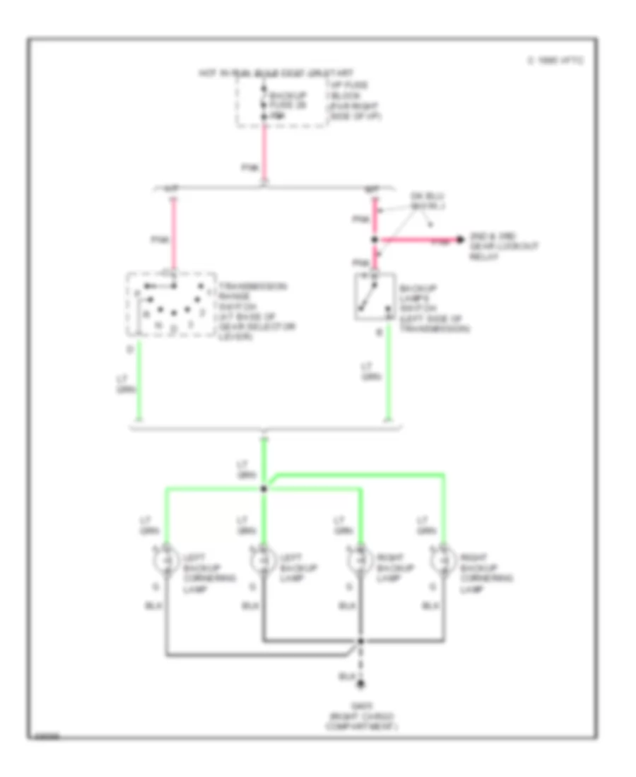
Back-up Lamps Wiring Diagram for Chevrolet Corvette ZR-1 1995
List of elements for Back-up Lamps Wiring Diagram for Chevrolet Corvette ZR-1 1995:
-
-
- 2nd & 3rd gear lockout relay
- A/t
- Backup fuse 28 15a
- Backup lamps switch (left side of transmission)
- C 1995 vftc
- G405 (right cargo compartment)
- Hot in run, bulb test or start
- I/p fuse block (far right side of i/p)
- Lamp
- Left backup cornering
- Left backup lamp
- M/t
- Pnk
- Right backup cornering
- Right backup lamp
- Transmission range switch (at base of gear selector lever)
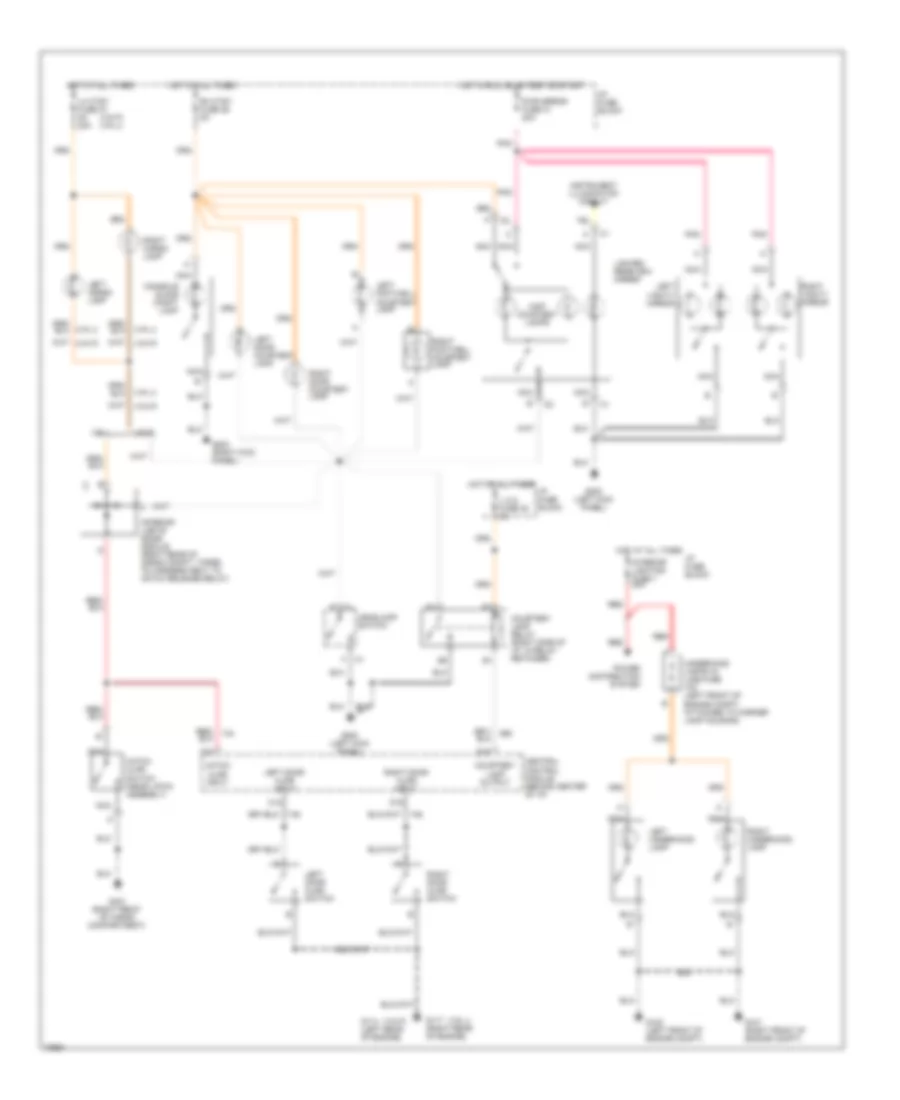
Exterior Light Wiring Diagram for Chevrolet Corvette ZR-1 1995
List of elements for Exterior Light Wiring Diagram for Chevrolet Corvette ZR-1 1995:
- (not used)
- 1995 vftc c
- A right front marker light b
- Brake lamp capacitor (taped next to brake switch)
- Brake switch assembly (under left i/p)
- Brake/traction control module
- C204
- C205
- Center high mounted stop lamp
- Central control module
- Cornering light switch
- Cornering lights
- Electronic
- G100 (left front of engine compartment)
- G101 (right front of engine compartment)
- G200 (left kick panel)
- G405 (right cargo compartment)
- Hazard
- Hazard flasher (behind right i/p)
- Hazard switch
- Head
- Headlamp switch
- Hot at all times
- Hot in run, bulb test or start
- I/p fuse block (far right side of i/p)
- Instrument cluster
- Left
- Left front marker light
- Left front park/ turn light
- Left tail/ stop/ turn lights
- Left turn ind.
- License lights
- Nca
- Normal
- Off
- Park
- Pnk
- Rear marker lights
- Right
- Right front park/ turn light
- Right tail/ stop/ turn lights
- Right turn ind.
- Stop/haz fuse 8 20a
- Tail fuse 6 15a
- Turn flasher (left of steering column)
- Turn fuse 24 10a
- Turn switch
- Turn/ hazard- switch assembly
- Vin j
- Vin j only
- Vin p
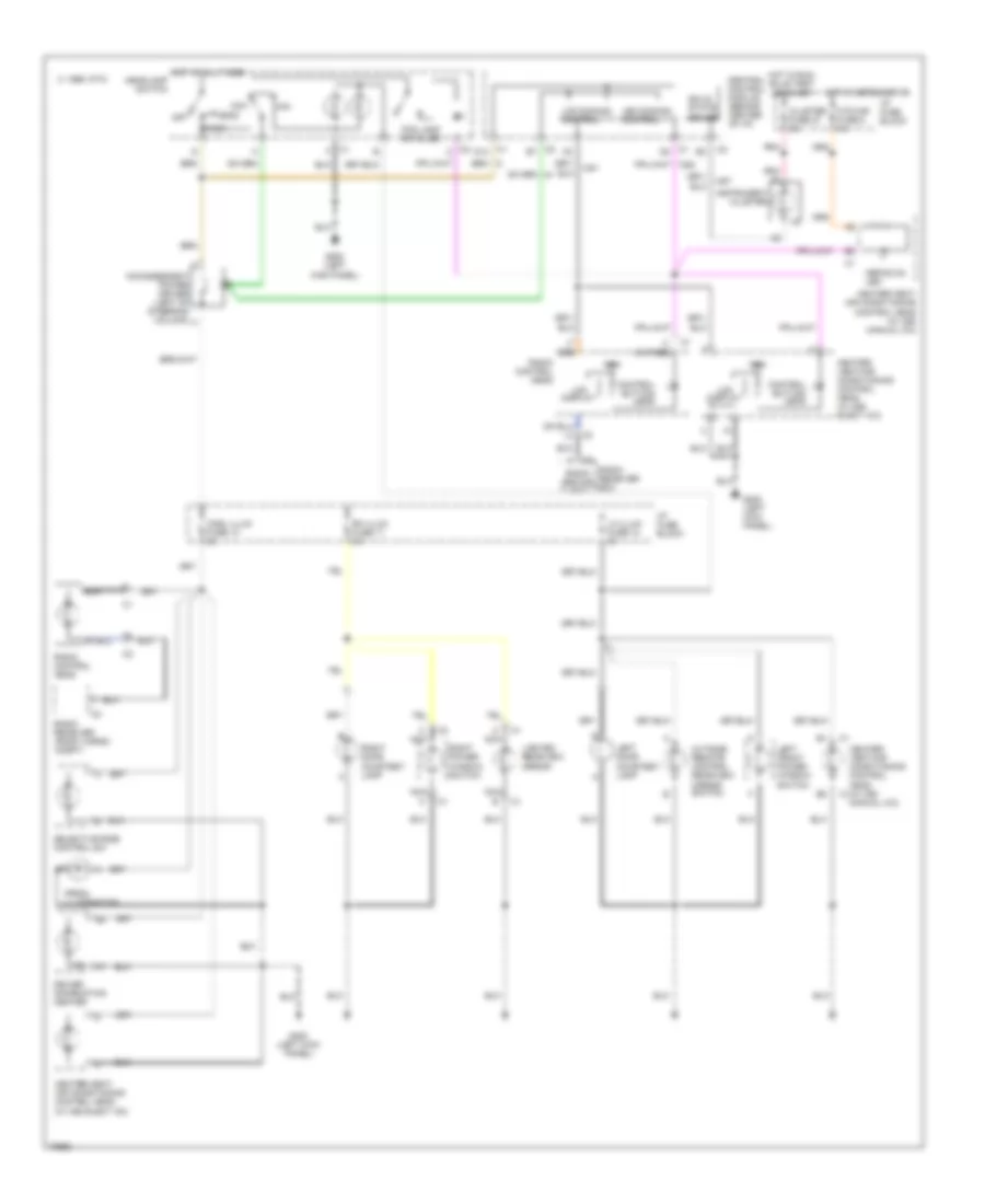
Exterior Light Wiring Diagram, with DRL for Chevrolet Corvette ZR-1 1995
List of elements for Exterior Light Wiring Diagram, with DRL for Chevrolet Corvette ZR-1 1995:
- (not used)
- Brake lamp capacitor (taped next to brake switch)
- Brake switch assembly (under left i/p)
- Brake/traction control module
- C204
- C205
- Center high mounted stop lamp
- Central control module
- Cornering light switch
- Cornering lights
- Daytime running lamps module
- Daytime running lamps module (center of i/p)
- Electronic
- Front marker lights
- G100 (left front of engine compartment)
- G101 (right front of engine compartment)
- G200 (left kick panel)
- G405 (right cargo compartment)
- Hazard
- Hazard flasher (behind right i/p)
- Hazard switch
- Head
- Headlamp switch
- Hot at all times
- Hot in run, bulb test or start
- I/p fuse block (far right side of i/p)
- Instrument cluster
- Left
- Left front park/ turn light
- Left tail/ stop/ turn lights
- Left turn ind.
- License lights
- Nca
- Normal
- Off
- Park
- Pnk
- Rear marker lights
- Right
- Right front park/ turn light
- Right tail/ stop/ turn lights
- Right turn ind.
- Stop/haz fuse 8 20a
- Tail fuse 6 15a
- Turn flasher (left of steering column)
- Turn fuse 24 10a
- Turn switch
- Turn/ hazard- switch assembly
- Vin j
- Vin j only
- Vin p
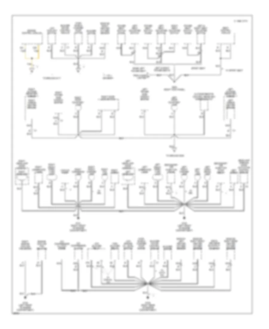
GROUND DISTRIBUTION
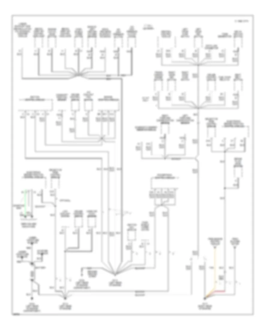
Ground Distribution Wiring Diagram (1 of 3) for Chevrolet Corvette ZR-1 1995
List of elements for Ground Distribution Wiring Diagram (1 of 3) for Chevrolet Corvette ZR-1 1995:
- "service abs" indicators
- 1995 vftc c
- 2nd & 3rd gear blockout solenoid
- A/c com- pressor clutch
- A/c com- pressor clutch diode
- A/c coolant fan switch
- A12
- A18
- B17
- Bank #1 left heated oxygen sensor
- Battery
- Braided ground strap
- Brake fluid level switch
- C12
- C32
- Camshaft position sensor
- Central control module
- Cruise control module
- Cruise control servo
- D16
- Data link connector
- Diagnostic energy reserve module
- E16
- Electronic brake/traction control module
- Engine control module
- Engine low oil level switch
- From blower motor
- From engine control module
- Fuel pump relay #1
- G104 (left rear of engine compartment)
- G114 (left rear of engine)
- G117 (right rear of engine)
- Ignition coil module
- Ignition control module
- Key-in ignition switch
- Left door ajar switch
- Left door key switch
- Left forward discriminating sensor
- Linear exhaust gas recirculation valve signal modifier module
- Low coolant switch
- Mass air flow sensor
- Nca
- Optional
- Powertrain control module
- Red
- Right door ajar switch
- Right door key switch
- Right forward discriminating sensor
- Seat belt switch
- Secon- dary sfi control module #1
- Secon- dary sfi control module #2
- Selective ride control module
- Shorting bar
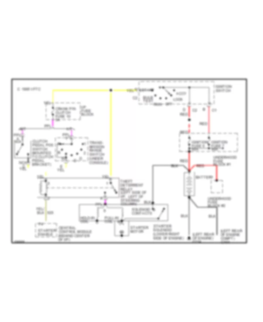
- Starter solenoid
- Tan
- Tone generator
- Trans- mission range switch
- Under- hood fuse block #1
- Under- hood fuse block #2
- Vin j
- Vin p
- W/ a/t only
- Wind- shield wiper motor
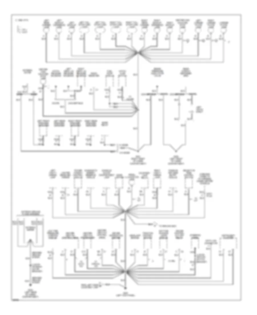
Ground Distribution Wiring Diagram (2 of 3) for Chevrolet Corvette ZR-1 1995
List of elements for Ground Distribution Wiring Diagram (2 of 3) for Chevrolet Corvette ZR-1 1995:
- 1995 vftc c
- 2nd & 3rd gear blockout solenoid
- 87a
- A/c compressor clutch
- A/c compressor clutch diode
- A21
- Bank #1 left heated oxygen sensor
- Bank #2 right front heated oxygen sensor
- Bank #2 right heated oxygen sensor
- Bank #2 right rear heated oxygen sensor
- Base left
- Blower motor
- Blower motor control module
- C20
- Control rearview mirror switch
- Engine control module
- Engine cooling fan relay #3
- From cigar c lighter
- G100 (left front of engine compartment)
- G101 (right front of engine compartment)
- G105 (right rear of engine compartment)
- G203 (right kick panel)
- Headlamp opening door actuator control module
- High blower relay
- Left & right power seats
- Left & right seat adjuster switch
- Left corn- ering lamp
- Left door courtesy lamp
- Left fog lamp
- Left front marker lamp
- Left front park/ turn lamp
- Left headlamp
- Left headlamp door assembly
- Left horn
- Left mirror heater ground
- Left outside rearview mirror
- Left power side window switch
- Left seat adjuster switch
- Left underhood lamp
- Low blower relay
- Low coolant switch
- Low engine oil level switch
- Nca
- Outside remote
- Power seat
- Power seat switch diode
- Right cornering lamp
- Right door courtesy lamp
- Right door lock switch
- Right engine cooling fan motor
- Right fog lamp
- Right front marker lamp
- Right front park/ turn lamp
- Right headlamp
- Right headlamp door assembly
- Right horn
- Right mirror heater ground
- Right outside rearview mirror
- Right power side window switch
- Right seat adjuster switch
- Right underhood lamp
- Seat control module
- Secondary air injection pump
- Secondary air injection pump relay
- Sport seat
- Tan
- To ground g117
- To ground g200
- Vacuum pump
- Vin j
- Vin p
- W/ auto a/c
- W/ drl
- W/ manual a/c
- W/ sport seat
- Wind- shield washer pump motor
Ground Distribution Wiring Diagram (3 of 3) for Chevrolet Corvette ZR-1 1995
List of elements for Ground Distribution Wiring Diagram (3 of 3) for Chevrolet Corvette ZR-1 1995:
- (braided ground strap)
- (lug on antenna motor bracket)
- (lug on ignition switch bracket)
- 1995 vftc c
- Accy plug
- Antenna ground plane harness
- Antenna motor
- Bose relay
- Brake pressure modulator valve
- C12
- Center high mounted stop lamp
- Cigar lighter
- Console glove compartment lamp
- Convertible
- Coupe
- Courtesy lamp relay
- Cruise control cut-off relay
- Data link connector
- Daytime running lamps module
- Diagnostic energy reserve module
- Driver information center
- From left door d courtesy lamp
- Fuel pump module
- G200 (left kick panel)
- G400 (left front of cargo compartment)
- G401 (right front of cargo compartment)
- G404 (left rear of cargo compartment)
- Hatch ajar switch
- Hatch release solenoid
- Headlamp switch
- Heater- vent-a/c control head
- Heater- vent-a/c programmer
- Instrument cluster
- Left backup cornering lamp
- Left backup lamp
- Left deck lid release solenoid
- Left front speaker/ amplifier
- Left hatch strut
- Left license plate lamp
- Left rear marker lamp
- Left rear speaker/ amplifier
- Left tail/ stop/turn lamp
- Left vanity mirror lamp
- License plate lamp
- Lighted rearview mirror
- Low tire pressure warning module
- Nca
- Passive keyless entry module
- Power window control module
- Prndl illumination lamp
- Radio receiver
- Rear window defogger grid
- Right backup cornering lamp
- Right backup lamp
- Right deck lid release solenoid
- Right front speaker/ amplifier
- Right license plate lamp
- Right rear marker lamp
- Right rear speaker/ amplifier
- Right tail/ stop/turn lamp
- Right vanity mirror lamp
- Selective ride control switch
- Steering wheel
- To ground g203
- Traction control switch
- Vin j
- Vin p
- W/ a/t
- W/ auto a/c
- W/ bose
- W/ coupe
- W/ drl
- W/ m/t
- W/ manual a/c
- W/o bose
- Wire end taped to i/p harness, under center console
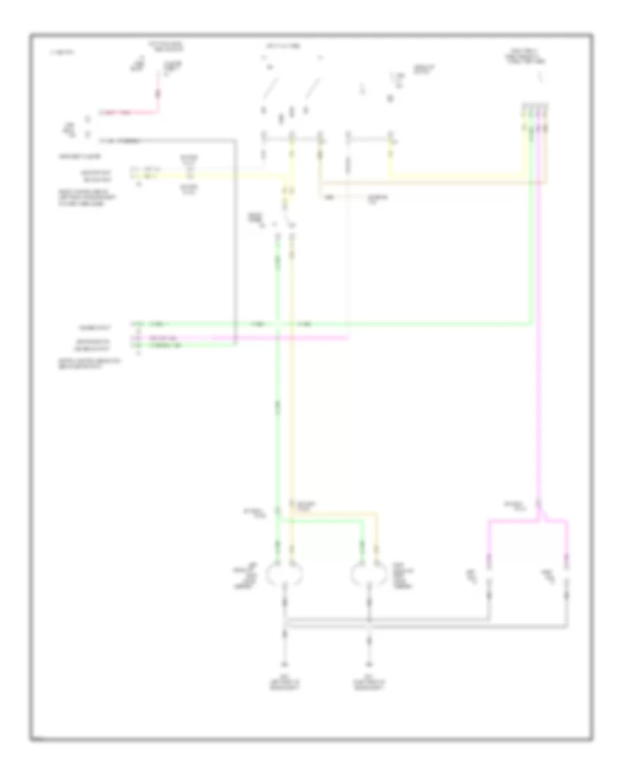
HEADLIGHTS
Headlamp Doors Wiring Diagram for Chevrolet Corvette ZR-1 1995
List of elements for Headlamp Doors Wiring Diagram for Chevrolet Corvette ZR-1 1995:
- B/h conn
- B/h conn pin a7
- Close
- G100 (left front of engine compt)
- Head
- Head off input rt door mtr ctrl power lt door mtr ctrl power headf on input ground
- Head park
- Headlamp opening door actuator control module (left front of engine compt, on inner wheelhouse)
- Headlamp switch
- Hot at all times
- Left headlamp door motor assembly
- Lh hdlp motor fuse 3 30a
- Off
- Open
- Park
- Pin c4
- Red
- Rh hdlp motor fuse 4 30a
- Right headlamp door motor assembly
- Underhood fuse block #2 (by battery, attached to inner wheelhouse)
Headlight Wiring Diagram, with DRL for Chevrolet Corvette ZR-1 1995
List of elements for Headlight Wiring Diagram, with DRL for Chevrolet Corvette ZR-1 1995:
- (behind center of i/p)
- (behind center of i/p, left
- (left door sill at base
- (left front of
- (left front of engine compt,
- (left kick
- (right front of
- (right side of i/p,
- (top of instrument panel)
- (vin j) 5a
- (vin p) 10a
- 15a
- All times
- Ambient light sensor
- Assembly
- B/h
- B/h conn
- B17
- Block
- Brake
- Ccm 3
- Central control module (ccm)
- Cluster
- Conn
- Conn c1
- Conn c2
- Conn c2 c
- Cruise
- Daytime running lamps
- Daytime running lts (drl) module
- Dimmer
- Door
- Drl control
- Engine compt)
- F15
- Fog
- Fog lt relay
- Fuse
- Fuse 16
- Fuse 27
- Fuse 32
- Fuse 6
- G100
- G101
- G200
- Head
- Head off input
- Head on input
- Headlamp
- Headlt
- Headlt control module
- Headlt relay
- Hi beam
- Hi beam in
- Hi beam ind ctrl
- Hot at
- Hot at all times
- Hot in run
- Hot in run, bulb
- I/p
- In relay retainer)
- Ind
- Instrument cluster
- Led dim ctrl
- Left
- Left drl relay
- Left front park/
- Logic
- Motor
- Of driver information center)
- Of park brake assembly)
- Off
- On inner wheelhouse)
- Panel)
- Park
- Park brake sw
- Park lt relay
- Pin a4
- Pin a7
- Pin b4
- Pin c4
- Pin f8
- Pnk
- Right
- Right drl relay
- Right front park/
- Solid
- State
- Switch
- Tail
- Tan
- Test or start
- Turn lamp
- Turn/hazard sw
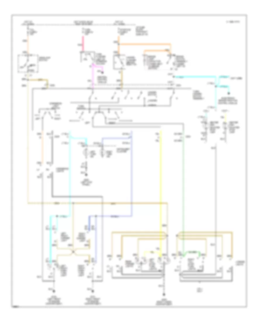
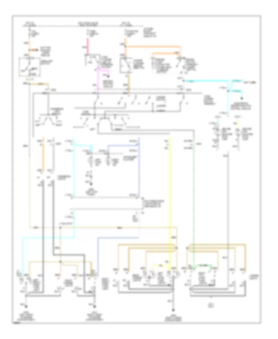
Headlight Wiring Diagram, without DRL for Chevrolet Corvette ZR-1 1995
List of elements for Headlight Wiring Diagram, without DRL for Chevrolet Corvette ZR-1 1995:
- (behind center of i/p)
- (left front of
- (left front of engine compt,
- (right front of
- (right side of i/p,
- 1995 vftc c
- Assembly
- B/h conn
- B17
- Beam
- Block
- Central control module (ccm)
- Cluster
- Dimmer
- Door
- Engine compt)
- Exterior
- F15
- Fog
- Fog lt relay
- Fuse
- Fuse 27
- G100
- G101
- Head
- Head off input
- Head on input
- Headlamp
- Headlt
- Headlt control module
- High
- High beam input
- High beam output
- Hot at all times
- Hot in run, bulb
- I/p
- In relay retainer)
- Ind
- Instrument cluster
- Led dimming ctrl
- Left
- Lts
- Motor
- Off
- On inner wheelhouse)
- Park
- Pin a4
- Pin a7
- Pin b4
- Pin c4
- Pin f8
- Pnk
- Right
- Switch
- Tan
- Test or start
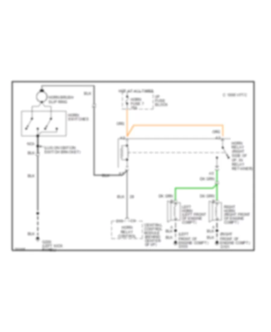
HORN
Horn Wiring Diagram for Chevrolet Corvette ZR-1 1995
List of elements for Horn Wiring Diagram for Chevrolet Corvette ZR-1 1995:
- (left front of engine compt) g100
- (lug on igntion switch bracket)
- (right front of engine compt) g101
- 1995 vftc c
- C16
- Central control module (behind center of i/p)
- G200 (left kick panel)
- Horn brush slip ring
- Horn fuse 7 15a
- Horn relay (right side of i/p, in relay retainer)
- Horn relay control
- Horn switches
- Hot at all times
- I/p fuse block
- Left horn (left front of engine compt)
- Nca
- Right horn (right front of engine compt)
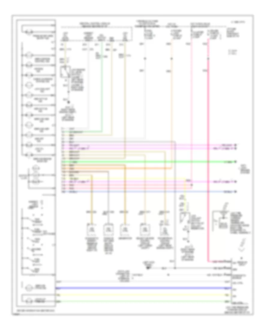
INSTRUMENT CLUSTER
Driver Information Center Wiring Diagram for Chevrolet Corvette ZR-1 1995
List of elements for Driver Information Center Wiring Diagram for Chevrolet Corvette ZR-1 1995:
- (bottom of coolant reservoir)
- (left kick panel) g200
- (lower left rear of engine)
- (lower right side of engine)
- 1995 vftc c
- A nca
- Abs active ind.
- Air bag ind.
- Ambient light sensor
- Ambient light sensor input
- Anti- lock brakes system
- Asr active ind.
- Asr off ind.
- B nca
- C nca
- C11
- Central control module (behind center of i/p)
- Check charging system ind.
- Cluster fuse 27 5 amp
- Cnsl illum fuse 13 5 amp
- Cruise fuse 32 10 amp 5 amp
- D13
- Data link connector (left of steering column)
- Diagnostic enable
- Diagnostic energy reserve module (behind right i/p)
- Dic switch input
- Dic switches
- Driver information center (dic)
- E10
- E11
- E15
- Eng/ met
- Fuel info
- Fuel reset
- G101 (right rear engine compt)
- G114 (left rear of engine)
- G117 (right rear of engine)
- Gauges
- Generator
- Grd
- Hot at all times
- Hot in run, bulb test or start
- I/p fuse block (far right side of i/p)
- Ign
- Ind. ctrl
- Low coolant ind.
- Low coolant switch
- Low engine oil level switch
- Low oil ind.
- Low oil ind. ctrl
- Low oil level input
- Low tire pressure warning module (behind center of i/p)
- Low tire pressure warning sensor assemblies (mounted inside each tire, strapped to wheel assembly)
- Low/flat tire ind.
- Mil ind. ctrl
- Of i/p)
- Passive keyless entry ind.
- Passive keyless entry module (behind center
- Pnk
- Power lock fuse 42 20 amp
- Powertrain control module (left rear engine compt)
- Receive input
- Ref grd
- Selective ride control module (left cargo compt)
- Service abs ind.
- Service asr ind.
- Service engine soon ind.
- Service ltpws ind.
- Service ride control ind.
- Solid state
- Switch illum.
- Trip reset
- Trip/ odo
- Variable voltage w/lights on & dimmer sw adjusted
- Vin j
- Vin p
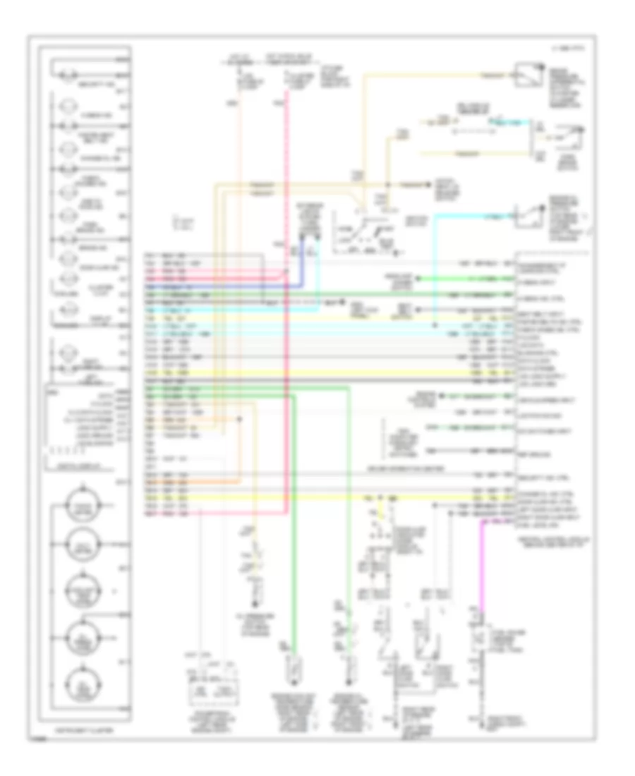
Instrument Cluster Wiring Diagram for Chevrolet Corvette ZR-1 1995
List of elements for Instrument Cluster Wiring Diagram for Chevrolet Corvette ZR-1 1995:
- (2 bulbs)
- (6 bulbs)
- (left kick
- (left rear of engine)
- (right front cargo compt)
- (right rear of engine)
- 0ne-to- four ind.
- 1313
- 1357
- 1359
- 1360
- 1365
- 1366
- 1368
- 1369
- 1374
- 1377
- 139
- 14
- 15
- 150
- 237
- 33
- 331
- 375
- 552
- 728
- 804
- 840
- 933
- A10
- A11
- A12
- A13
- A14
- A15
- A16
- A17
- Accy
- B10
- B11
- B12
- B13
- B14
- B15
- B16
- B17
- Blanking ctrl
- Brake ind.
- Brake pressure differential switch (in master cylinder reservoir)
- Bulb test
- C 1995 vftc
- C12
- C13
- Central control module (behind center of i/p)
- Change oil ind.
- Change oil ind. ctrl
- Check gages ind. ctrl
- Check gauges ind.
- Cl-1 data strobe
- Cl-2 data clock
- Cluster fuse 27 5 amp
- Cluster illum.
- Coolant temp gage
- D11
- D13
- D15
- D16
- Data
- Data clock
- Data strobe
- Dic switches input
- Digital display
- Display illum.
- Door ajar ind.
- Door ajar ind. ctrl
- Door ajar indicator diode module (right i/p)
- Driver information center
- Drl module (center i/p)
- E11
- E15
- Engine controls system
- Engine coolant temperature gage sensor (right rear of engine) (left side of engine)
- Engine oil pressure switch (top rear of engine) (lower right front of engine)
- Engine oil temperature sensor (left rear of engine) (right front of engine)
- Exterior lights system (turn/ hazard switch)
- F10
- F11
- F13
- F14
- F15
- F16
- Fasten belts ind. ctrl
- Fasten seat belt ind.
- Fuel gauge sender (top of fuel tank)
- Fuel level sig
- G114
- G117
- G200
- G401
- Grd
- Hatch/ deck lid release switch
- Headlamp dimmer switch
- Hi beam ind.
- Hi beam ind. ctrl
- Hi beam input
- Hot at all times
- Hot in run, bulb test or start
- I/p fuse block (far right side of i/p)
- Ignition switch
- Incandescent i/p lamps dim ctrl
- Ind. ctrl
- Instrument cluster
- Lcd blanking
- Lcd data
- Lcd fuse 38 5 amp
- Lcd logic grd
- Lcd pwm dim sig
- Left door ajar input
- Left door ajar switch
- Left turn ind.
- Lock
- Logic ground
- M clock
- Nca
- Off
- Oil press gage
- Oil pressure switch (top rear of engine)
- Oil temp gage
- Panel)
- Park brake ind.
- Park brake switch
- Pnk
- Pnk
- Powertrain control module (left rear engine compt)
- Ref ground
- Right door ajar input
- Right door ajar switch
- Right turn ind.
- Run
- Seat belt input
- Seat belt switch
- Security ind.
- Security ind. ctrl
- Start
- Tach output
- Tacho- meter
- Tan
- Tan/
- Trip computer & english/ metric switches
- Vehicle speed input
- Vin j
- Vin p
- Volt- meter
- W/ drl
- W/o drl
INTERIOR LIGHTS
Courtesy Lamp Wiring Diagram for Chevrolet Corvette ZR-1 1995
List of elements for Courtesy Lamp Wiring Diagram for Chevrolet Corvette ZR-1 1995:
- (vin j)
- (vin p)
- (vin p) (vin j)
- C1 b
- C1 f
- C10
- C12
- Central control module (behind center of i/p)
- Console glove compt lamp
- Courtesy lamp output
- Courtesy lamp relay (right side of i/p, in relay retainer)
- D12
- D16
- G100 (left front 0f engine compt)
- G101 (right front 0f engine compt)
- G114 (left rear of engine)
- G117 (right rear of engine)
- G200 (left kick panel)
- G203 (right kick panel)
- G401 (right front of cargo compartment)
- Hatch ajar input
- Hatch ajar switch (near latch assembly)
- Headlamp switch
- Hot at all times
- Hot in run, bulb test or start
- I/p fuse block
- Instrument illumination circuit
- Interior lighting fuse 1 20a
- Interior lights diode module (right rear of cargo compt, taped to harness next to hatch release relay)
- L.c.d. fuse 38 5a
- Left cargo lamp
- Left door ajar input
- Left door ajar switch
- Left door courtesy lamp
- Left footwell courtesy lamp
- Left underhood lamp
- Left vanity mirror
- Lh ctsy fuse 37 5a 20a
- Lighted rearview mirror
- Map/ courtesy lamps
- Nca
- Pnk
- Power distribution system
- Pwr mirror fuse 31 20a
- Red
- Rh ctsy fuse 36 5a
- Right cargo lamp
- Right door ajar input
- Right door ajar switch
- Right door courtesy lamp
- Right footwell courtesy lamp
- Right underhood lamp
- Right vanity mirror
- Underhood lamps in- line fuse 10a (left front of engine compt, attached to marker lamp housing)
- Vin j
- Vin p
Instrument Illumination Wiring Diagram for Chevrolet Corvette ZR-1 1995
List of elements for Instrument Illumination Wiring Diagram for Chevrolet Corvette ZR-1 1995:
- c1
- 1995 vftc c
- A nca
- C nca
- C1 d14
- C1 d2
- C1 f
- C2 c
- C2 e7
- Central control module (behind center of i/p)
- Cluster fuse 27 5a
- Cnsl illum fuse 13 5a
- Control button led's
- Defog on led
- Driver information center
- Fog lamp sw & led
- G200 (left kick panel)
- Head
- Headlamp switch
- Heater/ vent/air conditioning control head (w/ c60 manual a/c)
- Heater/ vent/air conditioning control head (w/ c68 elect a/c)
- Heater/vent/ air conditioning control head (w/ c60 manual a/c)
- Heater/vent/ air conditioning control head (w/ c68 elect a/c)
- Hot at all times
- Hot in run, bulb test or start
- Hot w/ defogger on
- Htd mir fuse 5 5a
- I/p fuse block
- Ign
- Incandescent power driver (left of steering column) c
- Instrument cluster
- Lcd dimming control
- Lcd display
- Led dimming control
- Left door courtesy lamp
- Left front power window switch
- Lh illum fuse 12 5a
- Lighted rearview mirror
- Max
- Min
- Nca
- Off
- Outside remote control rearview mirror switch
- Park
- Pnk
- Pnk a3
- Prndl illumination
- Radio control head
- Radio ground out
- Radio receiver (right cargo compt)
- Radio receiver box
- Rh illum fuse 11 5a
- Right door courtesy lamp
- Right power window switch
- Selective ride control sw
- Solid state driver
POWER ANTENNA
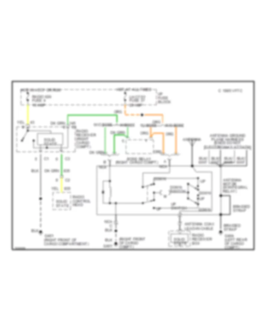
Power Antenna Wiring Diagram for Chevrolet Corvette ZR-1 1995
List of elements for Power Antenna Wiring Diagram for Chevrolet Corvette ZR-1 1995:
- (right cargo compt)
- (right front of cargo compt)
- 1995 vftc c
- Antenna
- Antenna coax lead-in cable
- Antenna ground plane harness (ends do not electrically attach)
- Antenna motor (w/integral relay)
- Bose relay
- Braided strap
- Down
- Down switch
- G401
- G401 (right front of cargo compartment)
- G404 (left rear of cargo compt)
- Hot at all times
- Hot in accy or run
- I/p fuse block
- Lh ctsy fuse 37 20 amp
- Nca
- Radio control head
- Radio ign fuse 4 10 amp
- Radio receiver (right cargo compt)
- Radio receiver box
- Solid state
- Up switch
- W/ bose
- W/bose
- W/o bose
POWER DISTRIBUTION
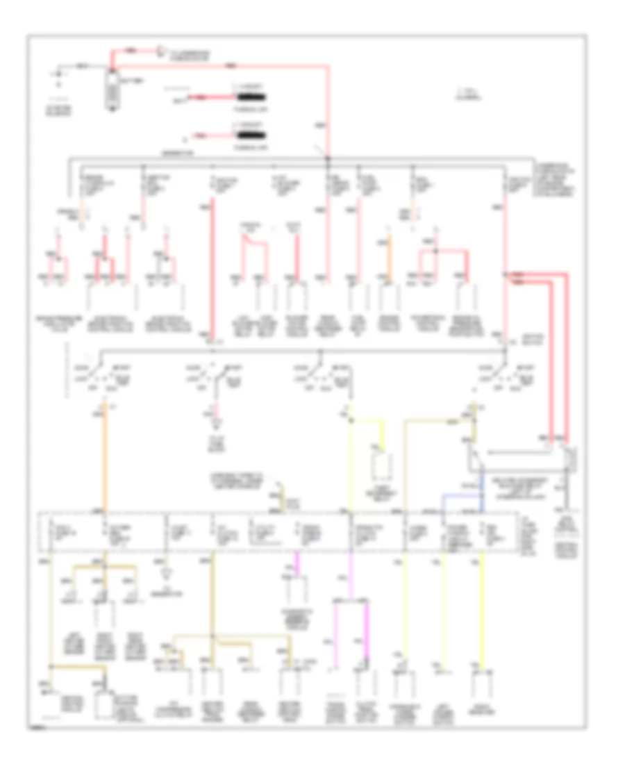
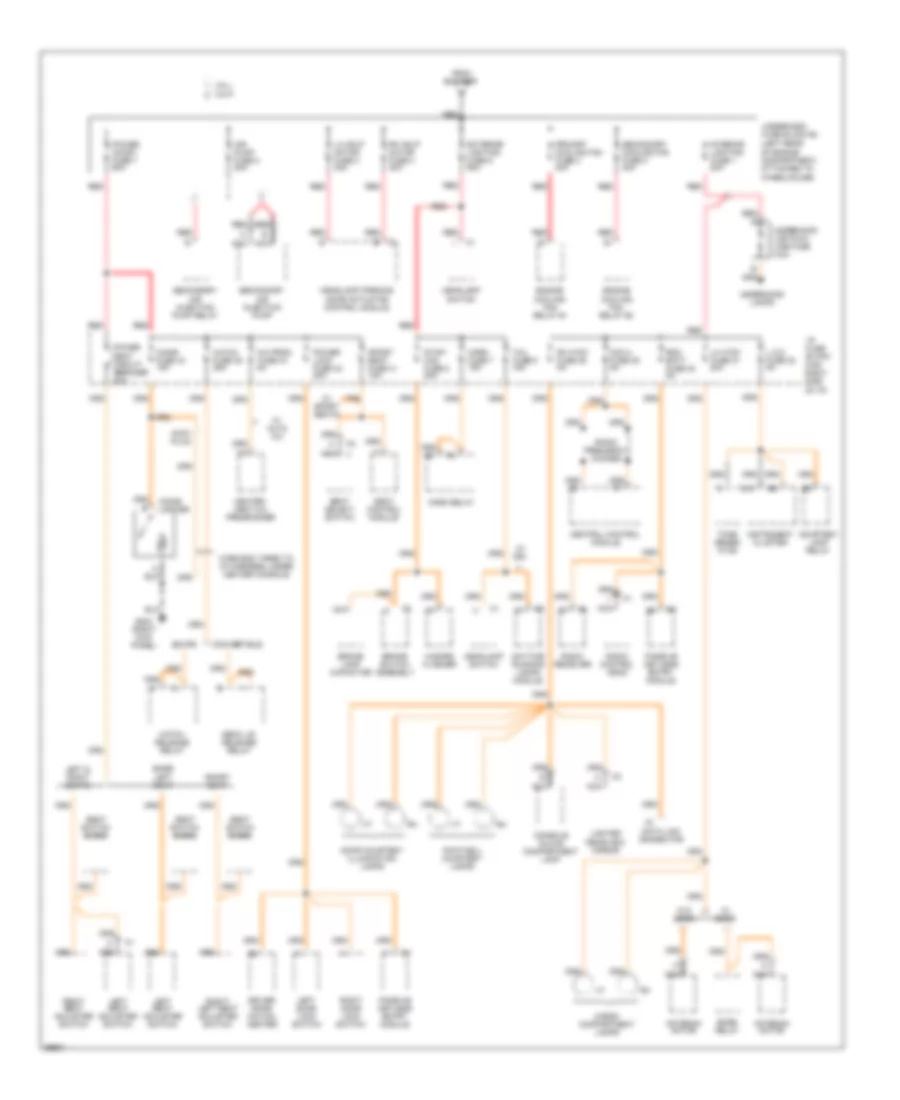
Power Distribution Wiring Diagram (1 of 4) for Chevrolet Corvette ZR-1 1995
List of elements for Power Distribution Wiring Diagram (1 of 4) for Chevrolet Corvette ZR-1 1995:
- (14-rust)
- (16-rust)
- (auto)
- (man)
- (optional)
- A/c
- A/c blower fuse 4 30a
- A/c clutch fuse 18 10a
- A/t
- Abs/tcs ecu fuse 3 30a
- Accy
- Accy plug
- Auto a/c
- B10
- B11
- B15
- B31
- Batt
- Battery
- Blower motor control module
- Brake hydraulic fuse 8 40a
- Brake pressure modulator valve
- Bulb test
- Ccm 3 fuse 16 5a
- Central control module
- Clutch pedal position switch
- Compressor clutch relay
- Crank airbag fuse 9 5a
- Crank p/n clutch fuse 10 5a
- Dab relay control
- Daytime running
- Delayed accessory bus (dab) relay (left of steering column)
- Diagnostic energy reserve module
- Ecm fuse 1 20a
- Electronic brake/traction control module
- Engine control module
- Engine oil pressure sensor/fuel pump switch
- Fuel pump fuse 2 20a
- Fuel pump relay #1
- Fusible link
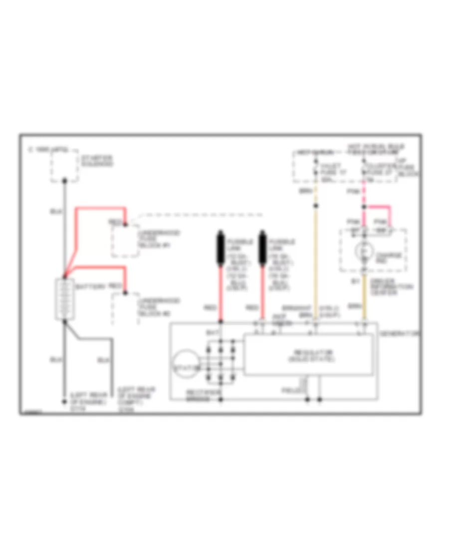
- Generator
- Heater- vent-a/c control head
- Heater- vent-a/c prog- rammer
- High blower motor relay
- I/p fuse block (far right side of i/p)
- Ignition fuse 6 60a
- Ignition fuse 7 40a
- Ignition switch
- Left heated oxygen sensor
- Left power window switch
- Lights module
- Lock
- Low blower motor relay
- M/t
- Manual a/c
- Nca
- Off
- Oxygen sen fuse 20 15a
- Pnk
- Power window circuit breaker 30a
- Powertrain control module
- Radio receiver
- Rd0 ign fuse 4 5a
- Rear window defogger relay
- Red
- Right front heated oxygen sensor
- Right rear heated oxygen sensor
- Rr defog fuse 5 30a
- Run
- Start
- Starter solenoid
- Theft deterrent relay
- To generator
- To i/p fuse block
- To underhood fuse block #2
- Trans- mission range switch
- Underhood fuse block #1 (left rear of engine compartment, on bulkhead)
- Utility fuse 9 15a
- Valet fuse 17 10a
- Vin j
- Vin p
- Windshield wiper/ washer switch
- Wiper fuse 3 30a
- Wire end taped to i/p harness, under center console
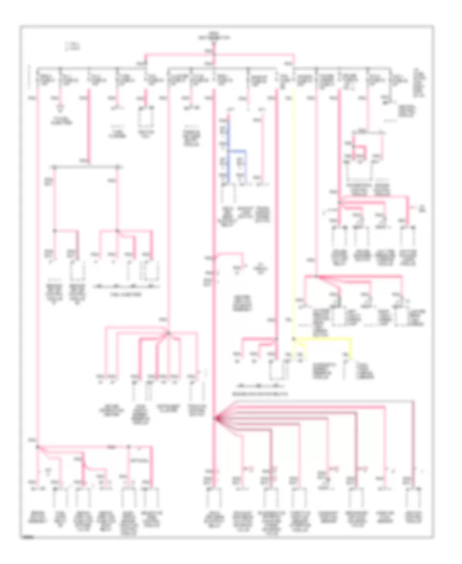
Power Distribution Wiring Diagram (2 of 4) for Chevrolet Corvette ZR-1 1995
List of elements for Power Distribution Wiring Diagram (2 of 4) for Chevrolet Corvette ZR-1 1995:
- (left rear
- A/c prog fuse 43 5a
- Accy plug
- Air pump fuse 8 20a
- Antenna motor
- B13
- Base left seat
- Bose relay
- Brake lamp capacitor
- Brake switch assembly
- Cargo compartment lamps
- Ccm 2 fuse 39 5a
- Central control module
- Cigar fuse 44 15a
- Cigar lighter
- Console glove compartment lamp
- Convertible
- Coupe
- Courtesy lamp relay
- Data link connector
- Daytime running lamps module
- Deck lid release relay
- Door courtesy illumination lamps
- Driver infor- mation center
- Engine cooling fan relay #1
- Engine cooling fan relay #2
- Exterior lighting fuse 6 60a
- Footwell courtesy lamps
- From battery
- G203 (right kick panel)
- Hatch fuse 45 25a
- Hatch release relay
- Hazard flasher
- Headlamp opening door actuator control module
- Headlamp switch
- Heater- vent-a/c programmer
- Horn fuse 7 15a
- Horn relay
- I/p fuse block (far right side of i/p)
- Instrument cluster
- Interior lighting fuse 1 20a
- L.c.d. fuse 38 5a
- Left & right seats
- Left door lock switch
- Left seat adjuster switch
- Lh ctsy fuse 37 20a
- Lh hdlp motor fuse 3 30a
- Lighted rearview mirror
- Nca
- Of engine compartment, attached to wheelhouse)
- Passive keyless entry module
- Power accsy fuse 7 60a
- Power lock fuse 42 20a
- Power seat circuit breaker 30a
- Primary cooling fan fuse 2 30a
- Radio control head
- Radio frequency chokes
- Radio receiver
- Rdo batt fuse 40 5a
- Red
- Rh ctsy fuse 36 5a
- Rh hdlp motor fuse 4 30a
- Right door lock switch
- Right seat adjuster switch
- Right/ left seat adjuster switch
- Seat control module
- Seat select switch
- Seat switch diode
- Secondary air injection pump
- Secondary air injection pump relay
- Secondary cooling fan fuse 5 40a
- Sport seat
- Sport seat fuse 41 10a
- Stop/ haz fuse 8 20a
- Tail fuse 6 15a
- Tone gener- ator
- Underhood fuse block #2
- Underhood lamps
- Underhood lights in- line fuse (10a)
- Vin j
- Vin p
- W/ auto a/c
- W/ bose
- W/ drl
- W/ sport seats
- W/o bose
- Wire end taped to i/p harness, under center console
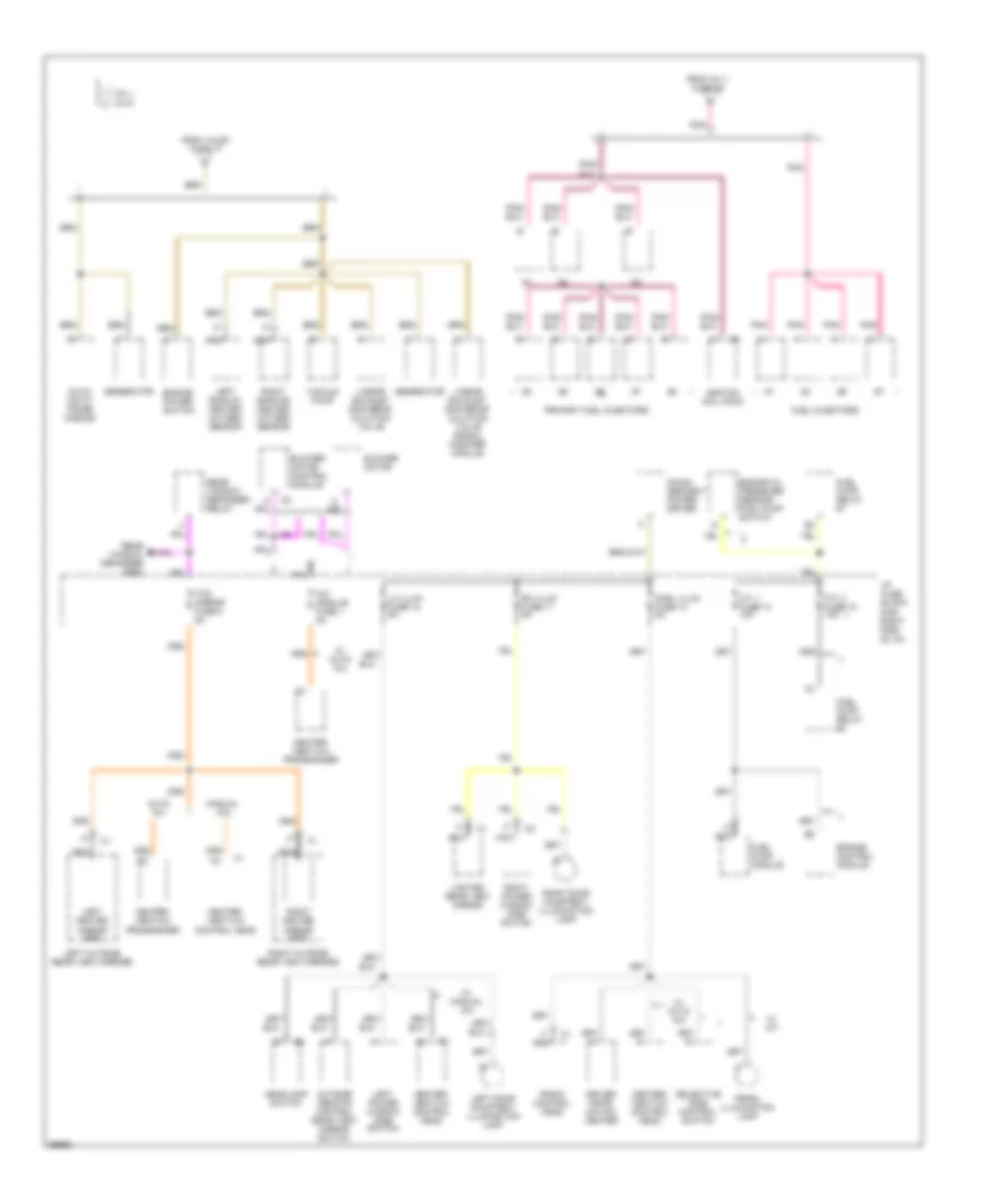
Power Distribution Wiring Diagram (3 of 4) for Chevrolet Corvette ZR-1 1995
List of elements for Power Distribution Wiring Diagram (3 of 4) for Chevrolet Corvette ZR-1 1995:
- 10a
- 2nd & 3rd gear blockout relay
- A/t
- A10
- Air bag fuse 34 20a
- B10
- B17
- B30
- Backup fuse 28 15a
- Backup lamp switch
- Brake switch assembly
- C16
- Camshaft position sensor
- Ccm 1 fuse 35 5a
- Central control module
- Cluster fuse 27 5a
- Coil fuse 25 10a
- Cruise control cut-off relay
- Cruise engaged switch
- Cruise fuse 32
- Daytime running lamps module
- Diag- nostic energy reserve module
- Diagnostic energy reserve module
- Driver information center
- Dual pole arming sensor
- E.c.m. fuse 33 5a
- Elec- tronic brake/ traction control module
- Eng 1 fuse 30 10a
- Eng 2 fuse 21 10a
- Engine control module
- Engine cooling fan relays
- Evaporative emission canister purge solenoid valve
- Exhaust gas recir- culation solenoid valve
- Fan fuse 5a
- From ignition switch
- Fuel injectors
- Fuel pump relay #2
- Heater- vent-a/c solenoid assembly
- I/p fuse block (far right side of i/p)
- Ignition coil
- Ignition control module
- Inj 1 fuse 22 10a
- Inj 2 fuse 23 10a
- Instrument cluster
- Left vanity mirror lamp
- Lighted rear view mirror
- Low tire pressure warning module
- M/t
- Mass air flow sensor
- Nca
- Optional
- Outside remote control rear view mirror switch
- P.k.e. fuse 26 5a
- Passive keyless entry module
- Pnk
- Power mirror fuse 31 5a
- Powertrain control module
- Right vanity mirror lamp
- Secon- dary air injection bypass valve
- Secon- dary air injection pump relay
- Second- ary sfi control module #1
- Second- ary sfi control module #2
- Secondary air inlet solenoid valve
- Selective ride control module
- Throttle position sensor interface module
- To fuel injectors
- Traction control switch
- Trans- mission range switch
- Turn flasher
- Turn fuse 24 5a
- Vin j
- Vin p
- W/ drl
- W/ manual a/c
Power Distribution Wiring Diagram (4 of 4) for Chevrolet Corvette ZR-1 1995
List of elements for Power Distribution Wiring Diagram (4 of 4) for Chevrolet Corvette ZR-1 1995:
- A/c module fuse 1 5a
- Auto a/c
- Auto- matic trans- mission
- Blower motor
- Blower motor control module
- Cnsl illum fuse 13 5a
- Defogger
- Driver infor- mation center
- Engine control module
- Engine oil pressure sensor/ fuel pump switch
- Engine power switch
- F.p. 1 fuse 14 10a
- F.p. 2 fuse 15 10a
- From inj 1 fuse 22
- From valet fuse 17
- Fuel injectors
- Fuel pump module
- Fuel pump relay #1
- Fuel pump relay #2
- Generator
- Grid
- Headlamp switch
- Heater- vent-a/c control head
- Heater- vent-a/c programmer
- Htd mirror fuse 5 5a
- I/p fuse block (far right side of i/p)
- Ignition coil pack
- Incan- descent power driver
- Left bank #1 heated oxygen sensor
- Left door courtesy/ illumination lamp
- Left heated mirror grid
- Left outside rear view mirrord
- Left power window side switch
- Lh illum fuse 12 5a
- Lighted rear view mirror
- Linear exhaust gas recir- culation valve
- Linear exhaust gas recir- culation valve signal modifier module
- Manual a/c
- Nca
- Outside remote control rear view mirror switch
- Pnk
- Primary fuel injectors
- Prndl illumination lamp
- Radio control head
- Rear
- Rear window defogger relay
- Rh illum fuse 11 5a
- Right bank #2 heated oxygen sensor
- Right door courtesy/ illumination lamp
- Right heated mirror grid
- Right outside rear view mirrord
- Right power window side switch
- Selective ride control switch
- Vacuum pump
- Vin j
- Vin p
- W/ a/t
- W/ auto a/c
- W/ manual a/c
- Window
POWER DOOR LOCKS
Power Door Lock Wiring Diagram for Chevrolet Corvette ZR-1 1995
List of elements for Power Door Lock Wiring Diagram for Chevrolet Corvette ZR-1 1995:
- (conv: in right door)
- (coupe: in rear of vehicle)
- (coupe: in right door) (conv: near i/p fuse block)
- (vin j)
- (vin p)
- 1692a
- 1692b
- 1692c
- 1995 vftc c
- All doors lock output hatch release output battery
- Antenna #1 ground diagnostic enable input program request input universal theft deterrent status
- Antenna input
- Arm universal theft deterrent
- Battery arm universal theft deterrent
- C5 tan
- Central control module
- Central control module (behind center of i/p)
- Conv
- Coupe
- Data link connector (below left side of i/p)
- Door key switch output signal
- Door lock motor right door unlock output c1
- Door unlock input
- Driver information center
- G114 (left rear of engine)
- G117 (right rear of engine)
- G200 (left kick panel)
- Ground
- Hot at all times
- Hot in run, bulb test or start
- I/p fuse block
- Ignition
- Key-in- ignition input
- Key-in- ignition switch
- Left door ajar input right door ajar input
- Left door ajar switch
- Left door key switch
- Left door lock motor
- Left door lock switch
- Left door unlock output indicator control
- Lock input
- Nca
- Passive keyless entry antenna #1 (in left door)
- Passive keyless entry antenna #2
- Passive keyless entry indicator
- Passive keyless entry module (behind center of i/p)
- Pke fuse 26 5a
- Pnk
- Power lock fuse 42 20a
- Program request output
- Rdo bat fuse 40 5a
- Right door ajar switch
- Right door key switch
- Right door lock motor
- Right door lock switch
- Shield ground
- T tan
- Tan
- Tan b
- Trunk release system
- U nca
- Universal theft deterrent status
- Unlock input
POWER MIRRORS
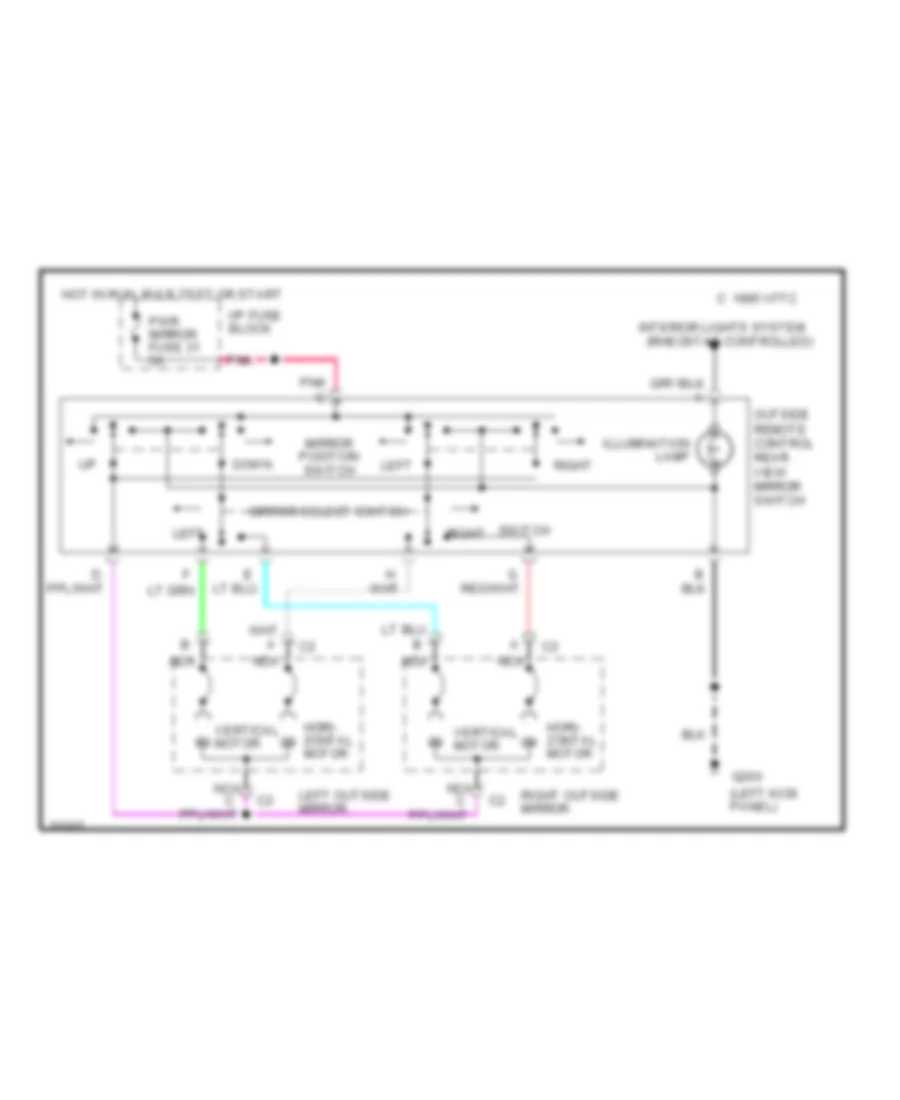
Power Mirror Wiring Diagram for Chevrolet Corvette ZR-1 1995
List of elements for Power Mirror Wiring Diagram for Chevrolet Corvette ZR-1 1995:
- (left kick panel)
- (rheostat controlled)
- 1995 vftc c
- Down
- G200
- Hori- zontal motor
- Hot in run, bulb test or start
- I/p fuse block
- Illumination lamp
- Interior lights system
- Left
- Left outside mirror
- Mirror position switch
- Mirror select switch
- Nca
- Outside remote control rear view mirror switch
- Pnk
- Pnk c
- Pwr mirror fuse 31 5a
- Right
- Right outside mirror
- Switch right
- Vertical motor
POWER SEATS
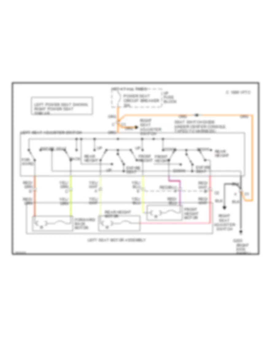
6-Way Power Seat Wiring Diagram for Chevrolet Corvette ZR-1 1995
List of elements for 6-Way Power Seat Wiring Diagram for Chevrolet Corvette ZR-1 1995:
- g203
- (right kick panel)
- 1995 vftc c
- Back
- Down
- Entire seat
- For- ward
- Forward/ back motor
- Front height
- Front height motor
- Hot at all times
- I/p fuse block
- Left power seat shown, right power seat similar
- Left seat adjuster switch
- Left seat motor assembly
- Power seat circuit breaker 30a
- Rear height
- Rear height motor
- Right seat adjuster switch
- Seat switch diode (under center console, taped to harness)
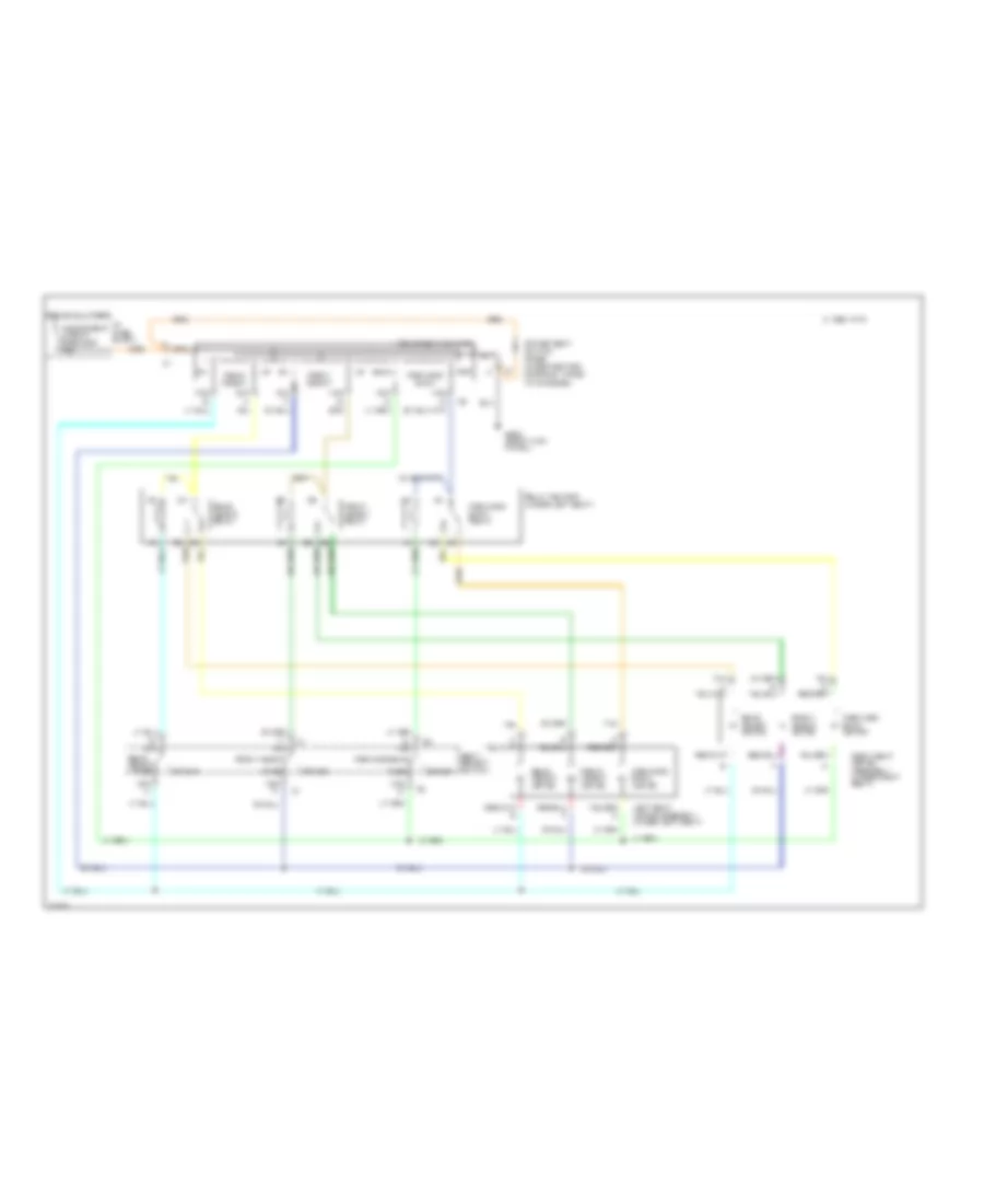
Sport Seats Wiring Diagram (1 of 2) for Chevrolet Corvette ZR-1 1995
List of elements for Sport Seats Wiring Diagram (1 of 2) for Chevrolet Corvette ZR-1 1995:
- 1995 vftc c
- Back
- C5 tan
- Driver
- E nca
- For
- Forward/ back
- Forward/ back motor
- Forward/ back relay
- Forward/back
- Front height
- Front height motor
- Front height relay
- G203 (right kick panel)
- Hot at all times
- I/p fuse block
- Left seat motor assembly (under left seat)
- Nca
- Nca a
- Nca c
- Nca d
- Pass
- Power seat circuit breaker 30a
- Power seat switch
- Power seat switch diode (under center console, taped to harness)
- Rear height
- Rear height motor
- Rear height relay
- Relay center (under left seat)
- Right seat motor assembly (under right seat)
- Seat select switch
- Tan
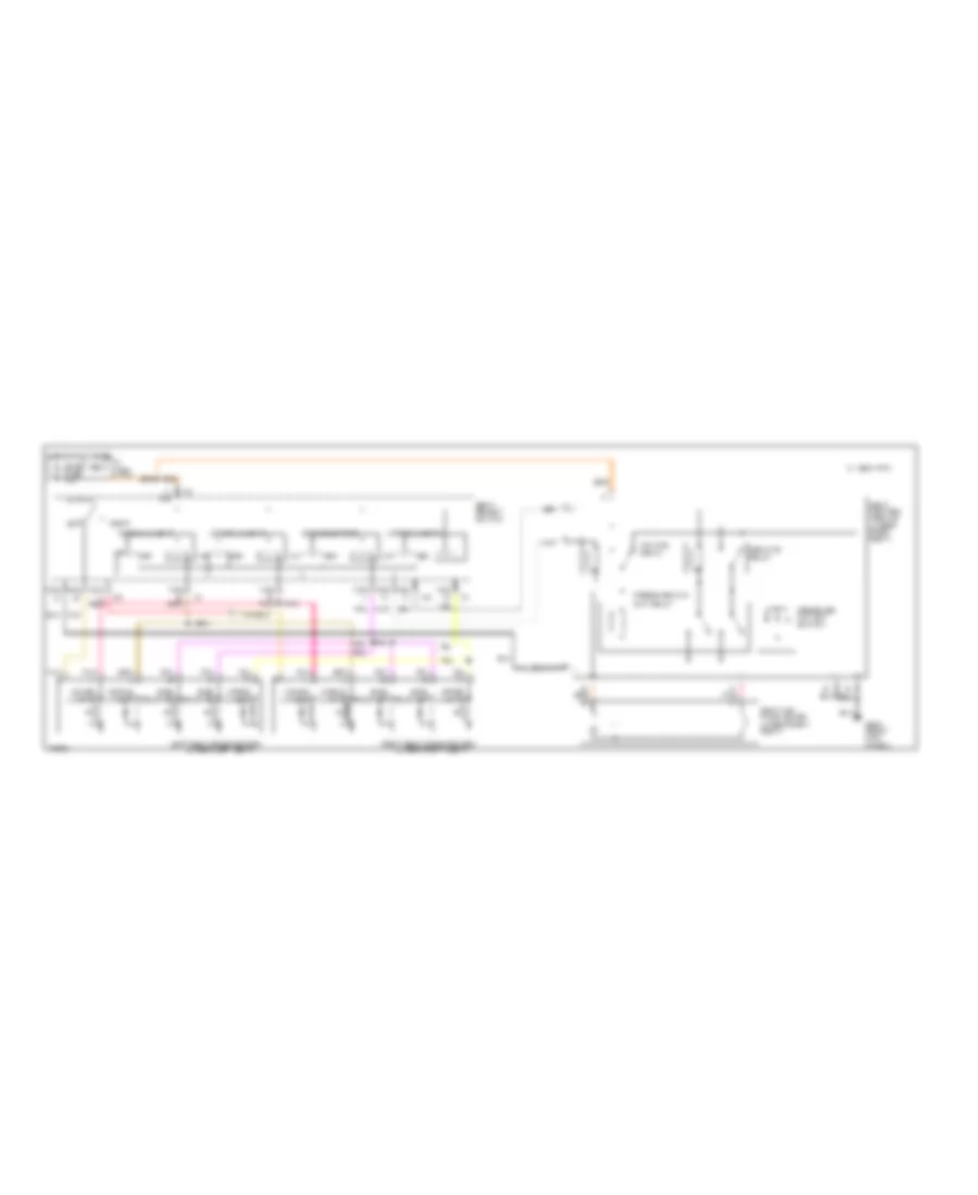
Sport Seats Wiring Diagram (2 of 2) for Chevrolet Corvette ZR-1 1995
List of elements for Sport Seats Wiring Diagram (2 of 2) for Chevrolet Corvette ZR-1 1995:
- (under left seat)
- (under right seat)
- 1995 vftc c
- C pnk a
- Def
- Deflate relay
- G203 (right kick panel)
- Hot at all times
- I/p fuse block
- Inf
- Inflate relay
- K nca
- Left
- Left seat solenoid box
- Lower lumbar
- Middle lumbar
- Nca a
- Nca b
- Nca c
- Nca d
- Nca f red
- Nca g pnk
- Nca h
- Nca j
- Pnk
- Pnk h
- Pressure cut- out relay
- Pressure cut-out switch
- Right
- Right seat solenoid box
- Seat air pump motor (under right seat)
- Seat control module (under right seat)
- Seat select switch
- Side bolster
- Side bolsters
- Sport seat fuse 10a
- Tan
- Tan f
- Upper lumbar
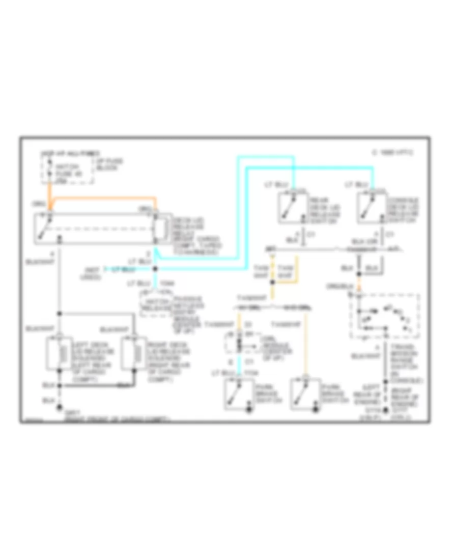
POWER TOP/SUNROOF
Convertible Top Wiring Diagram for Chevrolet Corvette ZR-1 1995
List of elements for Convertible Top Wiring Diagram for Chevrolet Corvette ZR-1 1995:
- (left rear of engine) g114 (vin p)
- (not used)
- (right rear of engine)
- (vin j)
- 1995 vftc c
- A c1
- A/t
- Console deck lid release switch
- Deck lid release relay (right cargo compt, taped to harness)
- Drl module (center of i/p)
- G117
- G401 (right front of cargo compt)
- Hatch fuse 45 25a
- Hatch release
- Hot at all times
- I/p fuse block
- Left deck lid release solenoid (left rear of cargo compt)
- M/t
- Park brake switch
- Passive keyless entry module (center of i/p)
- Rear deck lid release switch
- Right deck lid release solenoid (right rear of cargo compt)
- Trans- mission range switch (in console)
- W/ drl
- W/o drl
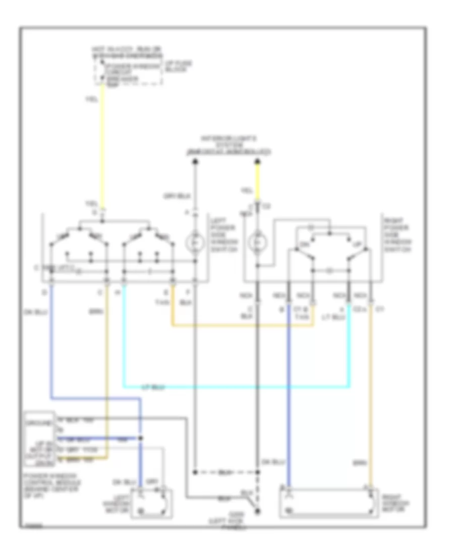
POWER WINDOWS
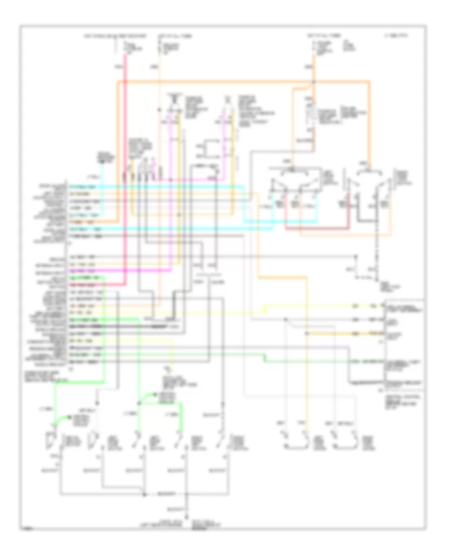
Power Window Wiring Diagram for Chevrolet Corvette ZR-1 1995
List of elements for Power Window Wiring Diagram for Chevrolet Corvette ZR-1 1995:
- (left kick
- 1995 vftc c
- B tan
- C nca
- Dn in
- G200
- Ground
- Hot in accy, run or with dab energized
- I/p fuse block
- Interior lights system (rheostat controlled)
- Left
- Left power side window switch
- Nca
- Panel)
- Power window circuit breaker 30a
- Power window control module (behind center of i/p)
- Right power side window switch
- Right window motor
- Tan
- Window motor
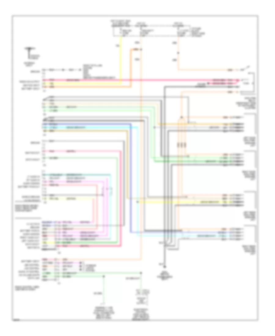
RADIO
Radio Wiring Diagrams, with Delco Bose for Chevrolet Corvette ZR-1 1995
List of elements for Radio Wiring Diagrams, with Delco Bose for Chevrolet Corvette ZR-1 1995:
- (or pnk)
- (right 'b' pillar) (coupe) g305 g303 (conv) (behind passenger's seat)
- 14 volts in
- 14 volts out
- 4k/mile vss output
- A17 (vin j) (vin p)
- Amplifier relay (near right side of instrument cluster)
- Antenna
- Antenna input
- Assembly line diagnostic link (aldl) connector (below left side of dash)
- Audio common
- Battery input
- Battery pwr in
- Battery pwr out
- Coaxial cable
- Data in/out
- Data link
- Electronic control module (ecm) (left rear of engine compt)
- G303 (behind passenger's seat)
- Ground
- Hot at all times
- Hot in accy, run & w/ delayed accessory bus
- I/p fuse block (right side of dash)
- Ignition in
- Ignition input
- Ignition out
- Incan lp control
- Interior lights system
- Lcd control
- Led control
- Left audio out
- Left door amplifier/ speaker unit
- Left rear amplifier/ speaker unit
- Lt audio in
- Lt ctsy fuse 20a
- Nca
- Pnk
- Power antenna
- Radio control head (center of dash)
- Radio on output
- Radio receiver box (right rear cargo compartment)
- Rdo batt fuse 5a
- Rdo ign fuse 5a
- Red
- Right audio out
- Right door amplifier/ speaker unit
- Right rear amplifier/ speaker unit
- Rt audio in
- Shield ground
- Tan
- Vs volume contr
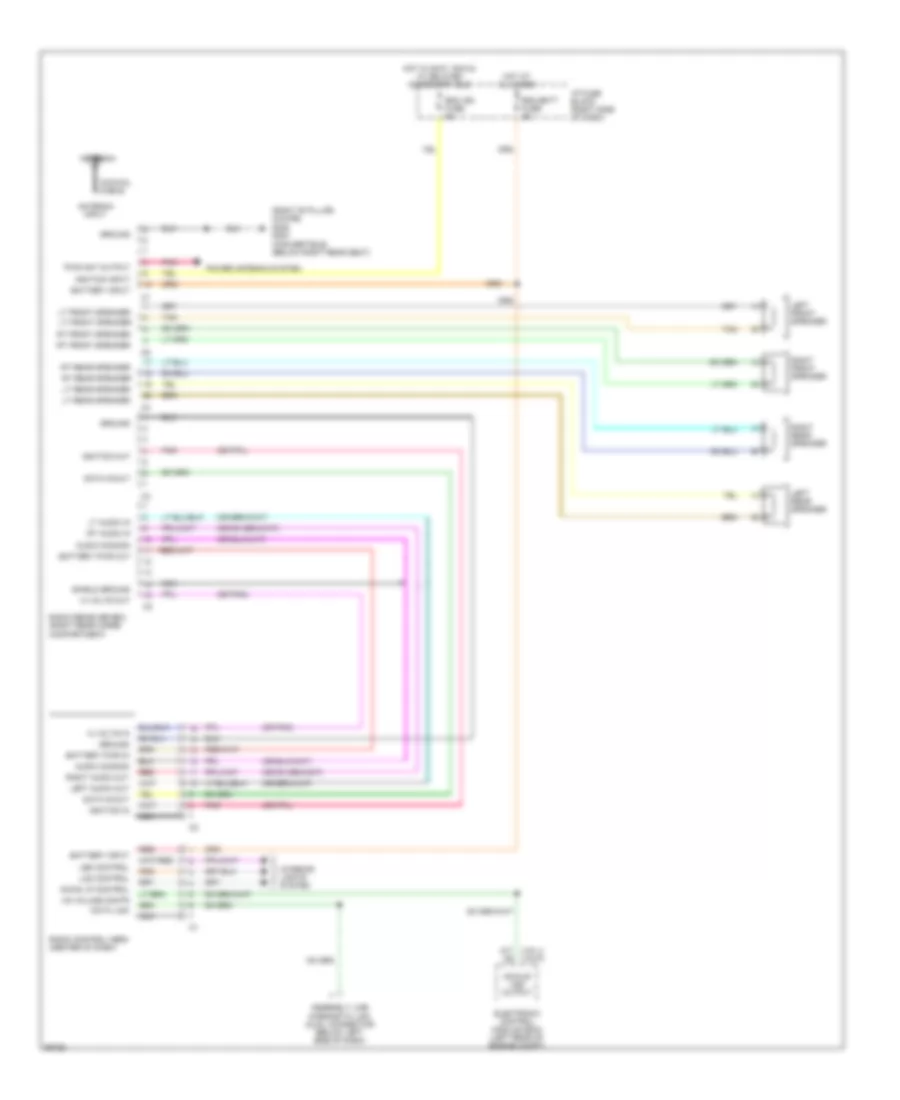
Radio Wiring Diagrams, without Delco Bose for Chevrolet Corvette ZR-1 1995
List of elements for Radio Wiring Diagrams, without Delco Bose for Chevrolet Corvette ZR-1 1995:
- (or pnk)
- (right 'b' pillar) (coupe) g305
- 14 volts in
- 14 volts out
- 4k/mile vss output
- A17 (vin j) (vin p)
- Antenna
- Antenna input
- Assembly line diagnostic link (aldl) connector (below left side of dash)
- Audio common
- Battery input
- Battery pwr in
- Battery pwr out
- Coaxial cable
- Data in/out
- Data link
- Electronic control module (ecm) (left rear of engine compt)
- G303 (convertible) (below right rear seat)
- Ground
- Hot at all times
- Hot in accy, run & w/ delayed accessory bus
- I/p fuse block (right side of dash)
- Ignition in
- Ignition input
- Ignition out
- Incan lp control
- Interior lights system
- Lcd control
- Led control
- Left audio out
- Left front speaker
- Left rear speaker
- Lt audio in
- Lt front speaker
- Lt rear speaker
- Nca
- Pnk
- Power antenna system
- Pwr ant output
- Radio control head (center of dash)
- Radio receiver box (right rear cargo compartment)
- Rdo batt fuse 5a
- Rdo ign fuse 5a
- Red
- Right audio out
- Right front speaker
- Right rear speaker
- Rt audio in
- Rt front speaker
- Rt rear speaker
- Shield ground
- Tan
- Vs volume contr
SHIFT INTERLOCKS
Shift Interlock Wiring Diagram for Chevrolet Corvette ZR-1 1995
List of elements for Shift Interlock Wiring Diagram for Chevrolet Corvette ZR-1 1995:
- (vin j)
- (vin p)
- 1995 vftc c
- Brake sw
- Brake switch assembly (top of brake pedal)
- Brake transmission shift interrupt diode (under center console, taped to harness)
- Brake transmission shift interrupt solenoid (under center console)
- C14
- C15
- Eng 2 fuse 21 10a
- G114 (left rear of engine)
- G117 (right rear of engine)
- Hot in run, bulb test or start
- I/p fuse block
- Park/ neutral input
- Pnk
- Pnk b
- Powertrain control module (above battery)
- Transmission range switch (under center console)
STARTING/CHARGING
Charging Wiring Diagram for Chevrolet Corvette ZR-1 1995
List of elements for Charging Wiring Diagram for Chevrolet Corvette ZR-1 1995:
- (left rear of engine compt) g104
- (left rear of engine) g114
- (not used)
- (solid state)
- 1995 vftc c
- Bat
- Battery
- Charge ind.
- Cluster fuse 27 5a
- Driver information center
- Field
- Generator
- Hot in run
- Hot in run, bulb test or start
- I/p fuse block
- Pnk
- Rectifier bridge
- Red
- Regulator
- Starter solenoid
- Stator
- Underhood fuse block #1
- Underhood fuse block #2
- Valet fuse 17 10a
Starting Wiring Diagram for Chevrolet Corvette ZR-1 1995
List of elements for Starting Wiring Diagram for Chevrolet Corvette ZR-1 1995:
- (left rear of engine compt) g104
- (left rear of engine) g114
- 1995 vftc c
- A/t
- Accy
- Battery
- Bulb test
- Central control module (behind center of i/p)
- Clutch pedal pos switch (mounted to clutch pedal bracket)
- Crank p/n clutch fuse 10 5a
- Hold-in coil
- I/p fuse block
- Ignition fuse 6 60a
- Ignition fuse 7 60a
- Ignition switch
- Lock
- M/t
- Off
- Pull-in coil
- Red
- Run
- Solenoid contacts
- Start
- Starter enable
- Starter motor
- Starter solenoid (lower right side of engine)
- Theft deterrent relay (left side of i/p, left of steering column)
- Trans- mission range switch (under console)
- Underhood fuse block #1
- Underhood fuse block #2
SUPPLEMENTAL RESTRAINTS
Supplemental Restraint Wiring Diagram for Chevrolet Corvette ZR-1 1995
List of elements for Supplemental Restraint Wiring Diagram for Chevrolet Corvette ZR-1 1995:
- 10.2k
- 2.49k
- 8.45k
- A10
- A11
- A12
- Air bag fuse 34 15a
- Air bag ind
- B10
- B11
- B12
- Central control module (behind center i/p)
- Cluster fuse 27 5a
- Crank air bag fuse 9 5a
- Crank input
- Data link connector (left side of i/p)
- Diagnostic energy reserve module (derm) (behind right side of i/p, left of i/p fuse block)
- Driver 36v lr
- Driver inflator module (middle of steering wheel)
- Driver information center
- Driver side "high"
- Driver side "low"
- Driver source sense
- Dual pole arming sensor (behind center of i/p)
- F10
- G114 (vin p) (left rear of engine)
- G117 (vin j) (right rear
- G117 (vin j) (right rear of engine)
- G200 (left kick panel)
- Ground
- Hot in run, bulb test or start
- Hot in start
- I/p fuse block
- Ign 1
- Left forward discriminating sensor (under battery, on frame rail)
- Nca
- Of engine)
- Pass 36v lr
- Pass side "high"
- Pass side "low"
- Pass source sense
- Passenger inflator module (right side of i/p)
- Pnk
- Redundant ind ground
- Redundant ind ign 1
- Right forward discriminating sensor (below blower motor housing, on frame rail)
- Seat belt input
- Seat belt sw
- Seat belt sw signal
- Shorting bar
- Sir coil assembly (top of steering column)
- Sir ind
- Tan
TRANSMISSION
5.7L
5.7L (VIN P), Transmission Wiring Diagram for Chevrolet Corvette ZR-1 1995
List of elements for 5.7L (VIN P), Transmission Wiring Diagram for Chevrolet Corvette ZR-1 1995:
- (engine harn, rear of engine compt)
- 1-2 shift
- 1-2 shift sol
- 2-3 shift sol
- 2-3 shift solenoid
- 3-2 ctrl solenoid
- 3-2 downshift sol
- 5v reference
- Automatic transmission
- Battery in
- Brake switch assembly (on brake pedal bracket)
- Brake switch input
- Class ii data
- Cluster fuse 27 5a
- Conn a
- Conn b
- Conn c
- Conn d
- Cruise control system
- Cruise signal in
- Data link connector (left side of dash)
- Driver information center
- Ecm fuse 1 20a
- Ecm fuse 33 5a
- Ect sens input
- Eng 2 fuse 21 10a
- Engine coolant temp sensor (front of engine, on water pump)
- G114 (left rear of engine)
- Hot at all times
- Hot in run
- Hot in run, bulb test or start
- I/p fuse block
- Ignition in
- Malfunction indicator lamp
- Mil control
- Park/neutral in
- Pcm ground
- Pcs hi
- Pcs lo
- Pnk
- Powertrain control module (pcm) (left rear of engine compt, above battery)
- Press ctrl
- Press sw assy
- Range signal "a"
- Range signal "b"
- Range signal "c"
- Red
- S101
- S103
- S104
- S116
- S120 (engine harn, 4 cm from map sensor break-out)
- S134 (engine harn, 10 cm from pcm break-out)
- S183
- S184 (eng harn, left rear of engine compt)
- S215
- S231
- S234 (i/p harn, 23 cm from lighter break-out)
- S235
- S240 (i/p harness, 6 cm from center console break-out)
- Sensor return
- Serial data
- Solenoid
- Tan
- Tcc
- Tcc pwm
- Tcc pwm sol
- Tcc sol
- Throttle position sensor (mounted to side of throttle body)
- Tp sens input
- Trans fluid temp sensor
- Trans range
- Trans temp sig in
- Transmission range switch (base of gear selector lever)
- Underhood fuse block 1
- Valet fuse 17 10a
- Vehicle speed sensor (left rear of transmission)
- Vss hi
- Vss lo
TRUNK, TAILGATE, FUEL DOOR
Hatch Release Wiring Diagram for Chevrolet Corvette ZR-1 1995
List of elements for Hatch Release Wiring Diagram for Chevrolet Corvette ZR-1 1995:
- 1995 vftc c
- A/t
- Console hatch release switch
- Drl module (center of i/p)
- G114 (vin p) (left rear of engine)
- G117 (vin j) (right rear of engine)
- G401 (right front of cargo compt)
- Hatch fuse 45 25a
- Hatch release
- Hatch release relay (rear of cargo compt taped to harness)
- Hatch release solenoid (rear of cargo compt)
- Hot at all times
- I/p fuse block
- Left door ajar switch
- Left door hatch release switch
- M/t
- Park brake switch
- Passive keyless entry module (center of i/p)
- Trans- mission range switch (in console)
- W/ drl
- W/o drl
WARNING SYSTEMS
Warning System Wiring Diagrams for Chevrolet Corvette ZR-1 1995
List of elements for Warning System Wiring Diagrams for Chevrolet Corvette ZR-1 1995:
- (left rear of engine)
- B17
- C11
- C12
- C13
- C14
- C15
- Central control module (behind center of i/p)
- Chime 1 input
- Chime 2 input
- Chime out control
- Cluster fuse 27 5a
- D14
- D16
- Exterior lights system
- F10
- Fasten belts indic ctrl
- G114
- Gnd
- Head
- Head- lamp switch
- Head/park switch in
- Hot at all times
- Hot in run, bulb test or start
- I/p fuse block
- Instrument cluster
- Key-in ignition in
- Key-in ignition switch
- Lcd fuse 38 5a
- Left door ajar switch
- Left door in
- Nca
- Off
- Park
- Pnk
- Power
- Powertrain control module (left rear of engine compt, above battery)
- Remote keyless entry system
- Right door ajar switch
- Right door in
- Seat belt switch
- Seat belt switch in
- Seat belts indic
- Tone generator (behind center of i/p)
- Turn flash in
- Turn flasher (below left side of i/p)
- Turn fuse 24 10a
- Vehicle speed output
- Vss in
WIPER/WASHER
Wiper/Washer Wiring Diagram for Chevrolet Corvette ZR-1 1995
List of elements for Wiper/Washer Wiring Diagram for Chevrolet Corvette ZR-1 1995:
- (left rear of eng) g114
- (right rear of eng) (right rear of eng compt) g117 g105
- (vin j)
- (vin j) (vin p)
- (vin p)
- 1.2m
- 1995 vftc c
- 24k
- Control board
- Hot in accy or run
- I/p fuse block
- Mechanical arm
- Mist
- Nca
- Nca f
- Off
- Park relay
- Pnk
- Pulse
- Pulse delay
- Solid state timer
- Washer switch
- Wind- shield wiper/ washer switch assembly
- Windshield washer pump motor
- Windshield wiper motor assembly
- Wiper fuse 3 30a
- Wiper switch

 Čeština
 Dansk
Dansk Deutsch
 Ελληνικά
 English
 English
 Suomi
Suomi Français
 Français
 עברית
עברית Hrvatski
 Magyar
 Italiano
 日本語
日本語 한국어
한국어 Nederlands
 Polski
 Português
 Português
 Română
 Русский
 Slovenčina
 Slovenščina
 Svenska
 Türkçe
 中文 (中国)